Vitocal 200-S Service and Installation10.8 MB - Viessmann
Vitocal 200-S Service and Installation10.8 MB - Viessmann
Vitocal 200-S Service and Installation10.8 MB - Viessmann

You also want an ePaper? Increase the reach of your titles
YUMPU automatically turns print PDFs into web optimized ePapers that Google loves.
Installation <strong>and</strong> service<br />
instructions<br />
for contractors<br />
VIESMANN<br />
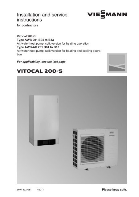
<strong>Vitocal</strong> <strong>200</strong>-S<br />
Type AWB 201.B04 to B13<br />
Air/water heat pump, split version for heating operation<br />
Type AWB-AC 201.B04 to B13<br />
Air/water heat pump, split version for heating <strong>and</strong> cooling operation<br />
For applicability, see the last page<br />
VITOCAL <strong>200</strong>-S<br />
5604 692 GB 7/2011 Please keep safe.
Safety instructions<br />
Safety instructions<br />
Please follow these safety instructions closely to prevent accidents <strong>and</strong> material<br />
losses.<br />
Safety instructions explained<br />
Danger<br />
This symbol warns against the<br />
risk of injury.<br />
!<br />
Please note<br />
This symbol warns against the<br />
risk of material losses <strong>and</strong> environmental<br />
pollution.<br />
Note<br />
Details identified by the word "Note" contain<br />
additional information.<br />
Target group<br />
These instructions are exclusively<br />
designed for qualified contractors.<br />
■ Work on the refrigerant circuit must<br />
only be carried out by qualified <strong>and</strong><br />
authorised refrigeration engineers<br />
■ Work on electrical equipment must<br />
only be carried out by a qualified electrician<br />
■ The system must be commissioned by<br />
the system installer or a qualified person<br />
authorised by the installer<br />
Regulations<br />
Observe the following when working on<br />
this system:<br />
■ National installation requirements<br />
■ Legal instructions regarding the prevention<br />
of accidents<br />
■ Legal instructions regarding environmental<br />
protection<br />
■ The Code of Practice of relevant trade<br />
associations<br />
■ All current safety regulations as<br />
defined by DIN, EN, DVGW, VDE <strong>and</strong><br />
all locally applicable st<strong>and</strong>ards<br />
a ÖNORM, EN <strong>and</strong> ÖVE<br />
c SEV, SUVA, SVTI <strong>and</strong> SWKI<br />
Working on the system<br />
■ Isolate the system from the power supply<br />
<strong>and</strong> check that it is no longer 'live',<br />
e.g. by removing the separate fuse or<br />
by means of a main isolator<br />
Note<br />
In addition to the control circuit, there<br />
may be several power circuits.<br />
Danger<br />
Contact with 'live' components<br />
can lead to severe injuries.<br />
Some components on the<br />
PCBs will remain 'live' even<br />
after the power supply has<br />
been switched off.<br />
Before removing covers from<br />
appliances, wait at least 4<br />
minutes for the power to dissipate.<br />
■ Safeguard the system against unauthorised<br />
reconnection<br />
5604 692 GB<br />
2
Safety instructions<br />
Safety instructions (cont.)<br />
!<br />
Please note<br />
Electronic assemblies can be<br />
damaged by electrostatic discharges.<br />
Before beginning work, touch<br />
earthed objects, such as heating<br />
or water pipes, to discharge static<br />
loads.<br />
Repair work<br />
!<br />
Please note<br />
Repairing components that fulfil a<br />
safety function can compromise<br />
the safe operation of your system.<br />
Replace faulty components only<br />
with original <strong>Viessmann</strong> spare<br />
parts.<br />
Auxiliary components, spare <strong>and</strong><br />
wearing parts<br />
Please note<br />
! Spare <strong>and</strong> wearing parts that<br />
have not been tested together<br />
with the system can compromise<br />
its function. Installing non-authorised<br />
components <strong>and</strong> making<br />
non-approved modifications or<br />
conversions can compromise<br />
safety <strong>and</strong> may invalidate our<br />
warranty.<br />
For replacements, use only original<br />
spare parts supplied or<br />
approved by <strong>Viessmann</strong>.<br />
5604 692 GB<br />
3
Index<br />
Installation instructions<br />
Preparing for installation<br />
Application............................................................................................................ 6<br />
Requirements for on-site connections.................................................................. 7<br />
Overview of possible system schemes................................................................ 9<br />
Designations in the system examples.................................................................. 11<br />
System example 1, ID: 4605169_1103_04.......................................................... 11<br />
System example 2, ID: 4605170_1103_04.......................................................... 19<br />
Installation sequence<br />
Installing the external unit..................................................................................... 27<br />
Installing the internal unit...................................................................................... 32<br />
Connecting the refrigerant lines........................................................................... 35<br />
Connecting a secondary circuit............................................................................ 41<br />
Connecting a cooling circuit if required................................................................ 42<br />
Electrical connections........................................................................................... 42<br />
Power supply........................................................................................................ 60<br />
Closing the heat pump......................................................................................... 66<br />
<strong>Service</strong> instructions<br />
Commissioning, inspection, maintenance<br />
Steps - commissioning, inspection <strong>and</strong> maintenance.......................................... 68<br />
Further details regarding the individual steps....................................................... 70<br />
Troubleshooting<br />
Repairs................................................................................................................. 88<br />
Internal unit parts lists<br />
Internal unit parts lists.......................................................................................... 99<br />
Overview of internal unit assemblies.................................................................... 100<br />
Internal unit parts not shown................................................................................ 101<br />
Casing, internal unit.............................................................................................. 101<br />
Electrical equipment, internal unit........................................................................ 103<br />
Hydraulics, internal unit, type AWB...................................................................... 105<br />
Hydraulics, internal unit, type AWB-AC................................................................ 107<br />
External unit parts lists<br />
External unit parts lists......................................................................................... 109<br />
External unit type AWB/AWB-AC 201.B04........................................................... 109<br />
External unit type AWB/AWB-AC 201.B07........................................................... 111<br />
Overview of the assemblies, external unit, type AWB/AWB-AC 201.B10, B13.... 113<br />
Casing, external unit, type AWB/AWB-AC 201.B10, B13.................................... 114<br />
4<br />
Index<br />
5604 692 GB
Index<br />
Index (cont.)<br />
Electrical equipment, external unit, type AWB/AWB-AC 201.B10, B13............... 116<br />
Hydraulics, external unit, type AWB/AWB-AC 201.B10, B13............................... 118<br />
Commissioning/service reports<br />
Hydraulic parameters report................................................................................. 120<br />
Control parameters report.................................................................................... 120<br />
Specification....................................................................................................... 125<br />
Appendix<br />
Heat pump commissioning order.......................................................................... 130<br />
Certificates<br />
Declaration of conformity...................................................................................... 131<br />
Keyword index.................................................................................................... 132<br />
5604 692 GB<br />
5
Preparing for installation<br />
Application<br />
The heat pumps <strong>Vitocal</strong> <strong>200</strong>-S,<br />
type AWB <strong>and</strong> AWB-AC can be used for<br />
the following purposes:<br />
■ Central heating via a heating system<br />
■ Central cooling (only type AWB-AC)<br />
via a heating system<br />
■ DHW heating<br />
Note<br />
<strong>Vitocal</strong> <strong>200</strong>-S is intended exclusively for<br />
domestic use, i.e. even people who have<br />
not had any instruction are able to operate<br />
the appliance safely.<br />
Any use that differs from or goes beyond<br />
this is not appropriate.<br />
5604 692 GB<br />
6
Preparing for installation<br />
Requirements for on-site connections<br />
Internal unit<br />
A B<br />
450<br />
360<br />
360<br />
58<br />
50<br />
40<br />
905<br />
150<br />
AB /<br />
960<br />
75<br />
147<br />
219<br />
294<br />
369<br />
+<br />
1105<br />
41<br />
5604 692 GB<br />
Installation<br />
7
Preparing for installation<br />
Requirements for on-site connections (cont.)<br />
Symbol Meaning Connection<br />
Refrigerant lines from/to the Type Pipe 7 UNF thread<br />
external unit:<br />
AWB/<br />
AWB-AC<br />
■ Hot gas line 201.B04 12 mm ⅞<br />
Reducer<br />
⅞ x ¾<br />
+<br />
201.B07<br />
201.B10<br />
201.B13<br />
16 mm<br />
16 mm<br />
16 mm<br />
■ Liquid line 201.B04 6 mm ⅝<br />
Reducer<br />
⅝ x ⁷⁄₁₆<br />
DHW cylinder flow (heating<br />
water side)<br />
Heating water return <strong>and</strong><br />
DHW cylinder return<br />
Heating water flow<br />
201.B07<br />
201.B10<br />
201.B13<br />
10 mm<br />
10 mm<br />
10 mm<br />
⅞<br />
⅞<br />
⅞<br />
⅝<br />
⅝<br />
⅝<br />
G 1¼<br />
G 1¼<br />
G 1¼<br />
A Cable entry 42 V<br />
1. Preparing connections on the heating<br />
water <strong>and</strong> the DHW side.<br />
Flush the heating system.<br />
2. Prepare the electrical connections.<br />
Note<br />
The internal/external unit BUS connecting<br />
cable can be routed along the<br />
refrigerant line <strong>and</strong> fixed to it.<br />
Cable lengths inside the internal/external unit plus wall clearance:<br />
Cables Internal unit External unit<br />
Power cables:<br />
Heat pump control unit (230 V~) 2.0 m —<br />
Compressor (230 V~) — 1.5 m<br />
Additional connecting cables:<br />
230 V~, e.g. for pumps 2.0 m —<br />
< 42 V, e.g. for sensors 2.0 m —<br />
8<br />
5604 692 GB
Preparing for installation<br />
Requirements for on-site connections (cont.)<br />
Cables Internal unit External unit<br />
Connecting cables between the internal/external units:<br />
12 V BUS 1.5 m 1.5 m<br />
43 V BUS 1.5 m 1.5 m<br />
Recommended power cables<br />
<strong>Vitocal</strong> <strong>200</strong>-S, type AWB, 201.B04 201.B07 201.B10 201.B13<br />
AWB-AC<br />
External unit (compressor)<br />
230 V~<br />
Cable cross-section 3 x 2.5 mm 2 3 x 2.5 mm 2 3 x 2.5 mm 2 3 x 4.0 mm 2<br />
Max. cable length 29 m 25 m 16 m 20 m<br />
or or<br />
Cable cross-section – – 3 x 4.0 mm 2 3 x 6.0 mm 2<br />
Max. cable length – – 26 m 30 m<br />
Heat pump control unit (internal<br />
unit) 230 V~<br />
Cable cross-section<br />
■ Without power-OFF 3 x 1.5 mm 2 3 x 1.5 mm 2 3 x 1.5 mm 2 3 x 1.5 mm 2<br />
■ With power-OFF 5 x 1.5 mm 2 5 x 1.5 mm 2 5 x 1.5 mm 2 5 x 1.5 mm 2<br />
Instantaneous heating water<br />
heater<br />
Cable cross-section<br />
■ 400 V~ 5 x 2.5 mm 2 5 x 2.5 mm 2 5 x 2.5 mm 2 5 x 2.5 mm 2<br />
■ 230 V~ 7 x 2.5 mm 2 7 x 2.5 mm 2 7 x 2.5 mm 2 7 x 2.5 mm 2<br />
Max. cable length 25 m 25 m 25 m 25 m<br />
Installation<br />
Overview of possible system schemes<br />
The following table provides an overview<br />
of all possible system schemes.<br />
5604 692 GB<br />
9
Preparing for installation<br />
Overview of possible system schemes (cont.)<br />
Components System scheme (parameter 7000)<br />
0 1 2 3 4 5 6<br />
Heating circuit<br />
A1/HC1 – X X – – X X<br />
M2/HC2 – – – X X X X<br />
DHW cylinder<br />
X – X – X – X<br />
Heating water buffer cylinder<br />
– 0 0 X X X X<br />
External heat source<br />
– 0 *1 0 *1 0 0 0 0<br />
Cooling<br />
A1/HC1 0 0 0 0<br />
M2/HC2 0 0 0 0<br />
Sep. cooling circuit 0 0 0 0 0 0 0<br />
X Component has been selected.<br />
0 Component can be added.<br />
*1<br />
Only in conjunction with a heating water buffer cylinder.<br />
5604 692 GB<br />
10
Preparing for installation<br />
Designations in the system examples<br />
oE<br />
--2/F14--<br />
oQ<br />
oW<br />
-2/145-<br />
A1<br />
2<br />
oE<br />
--2/F14--<br />
iE<br />
--2/X3.8;3.9--<br />
oR<br />
--2/211.2--<br />
oP<br />
Installation<br />
[H F<br />
[YF F<br />
--F6--<br />
--212.3--<br />
--F8--<br />
--F0--<br />
2<br />
--211.4--<br />
--211.2--<br />
--F14--<br />
--230V-- -KM BUS-<br />
-2/X3.8;3.9-<br />
System example 1, ID: 4605169_1103_04<br />
Setting system scheme 6<br />
■ Internal unit of the heat pump<br />
type AWB 201.B without instantaneous<br />
heating water heater or<br />
type AWB-AC 201.B with instantaneous<br />
heating water heater<br />
■ 1 radiator heating circuit without mixer<br />
A1/HC1<br />
■ 1 underfloor heating circuit with mixer<br />
M2/HC2<br />
■ DHW heating<br />
■ External heat source<br />
■ Heating water buffer cylinder<br />
Note<br />
This scheme is a basic example without<br />
shut-off devices or safety equipment.<br />
This does not replace the need for local<br />
engineering.<br />
5604 692 GB<br />
11
Preparing for installation<br />
System example 1, ID: 4605169_1103_04 (cont.)<br />
Hydraulic installation scheme<br />
--2--<br />
-KM BUS-<br />
105<br />
--20--<br />
-230V-<br />
91 -8/145- 71 -8/145-<br />
73<br />
--105/2--<br />
70<br />
90 -105/20--76-<br />
A1<br />
M2<br />
74<br />
--2/212.2--<br />
96<br />
--74/20--<br />
76<br />
77<br />
--105/52--<br />
62<br />
--2/F13--<br />
--2/F6--<br />
31<br />
WW<br />
37<br />
--2/212.3--<br />
52<br />
--2/224.7--<br />
53<br />
--2/F20--<br />
54<br />
--2/222.1;2--<br />
3<br />
--2/F0--<br />
29<br />
5<br />
1<br />
12<br />
13<br />
4<br />
6<br />
55<br />
-2/222.4--51-<br />
--2/F4--<br />
61<br />
KW<br />
30<br />
50<br />
14<br />
-2/211.2--14-<br />
60<br />
2<br />
--230V--<br />
--211.2--<br />
--212.3--<br />
--224.7--<br />
--222.1;2--<br />
--212.2--<br />
--222.4--<br />
--F6--<br />
--KM BUS--<br />
--F20--<br />
--F0--<br />
--F13--<br />
--F4--<br />
--52--<br />
27 28<br />
15<br />
-2/X3.3;3.4-<br />
--145--<br />
--145--<br />
--145--<br />
--145--<br />
8<br />
5604 692 GB<br />
--X3.3;3.4--<br />
12
System example 1, ID: 4605169_1103_04 (cont.)<br />
Preparing for installation<br />
Pos. Designation<br />
Heat source<br />
1 Internal unit, heat pump <strong>Vitocal</strong> <strong>200</strong>-S<br />
2 Heat pump control unit Vitotronic <strong>200</strong>, type WO1B<br />
3 Outside temperature sensor ATS<br />
4 Instantaneous heating water heater with control module<br />
(only for <strong>Vitocal</strong> <strong>200</strong>-S, type AWB-AC)<br />
5 3-way diverter valve for "Central heating/DHW heating"<br />
6 Secondary pump<br />
8 KM BUS distributor<br />
qE Heating circuit expansion vessel<br />
qT Flow switch<br />
Primary circuit<br />
wU Liquid line<br />
wI Hot gas line<br />
wO External unit of the heat pump <strong>Vitocal</strong> <strong>200</strong>-S<br />
DHW heating<br />
eP DHW cylinder (dual mode)<br />
eQ Cylinder temperature sensor STS<br />
eU DHW circulation pump ZP<br />
5604 692 GB<br />
Installation<br />
13
Preparing for installation<br />
System example 1, ID: 4605169_1103_04 (cont.)<br />
Pos.<br />
qR<br />
tP<br />
tQ<br />
tW<br />
tE<br />
tR<br />
tT<br />
zP<br />
zQ<br />
zW<br />
uP<br />
uQ<br />
uE<br />
uR<br />
uZ<br />
uU<br />
q-T<br />
oP<br />
oQ<br />
oZ<br />
Designation<br />
External heat source<br />
High limit safety cut-out for switching off the secondary pump<br />
External heat source, e.g. oil/gas boiler<br />
Dem<strong>and</strong> of external heat source (connection to heat pump control unit)<br />
Circulation pump for cylinder heating UPSB<br />
Boiler water temperature sensor KTS (for connection to the heat pump<br />
control unit):<br />
■ As contact temperature sensor<br />
or<br />
■ As immersion temperature sensor<br />
Mixer motor, directly controlled<br />
High limit safety cut-out STB 70 °C (to switch off the external heat<br />
source)<br />
Heating water buffer cylinder<br />
Buffer temperature sensor PTS<br />
System flow temperature sensor<br />
Heating circuit with mixer M2 (KM BUS)<br />
Underfloor heating circuit<br />
Vitotrol <strong>200</strong>A remote control<br />
Flow temperature sensor<br />
Temperature limiter to restrict the maximum temperature of underfloor<br />
heating systems<br />
■ As immersion thermostat<br />
or<br />
■ As contact thermostat<br />
Heating circuit pump<br />
3-way mixer, heating circuit<br />
Mixer motor in 3-way mixer<br />
Mixer extension kit<br />
Heating circuit without mixer A1<br />
Radiator heating circuit<br />
Vitotrol <strong>200</strong>A remote control<br />
Heating circuit pump<br />
Electrical installation scheme<br />
For an overview of the electrical connections<br />
<strong>and</strong> more information on the PCBs,<br />
see from page 45 <strong>and</strong> the separate<br />
service instructions for the heat pump<br />
control unit.<br />
For information regarding the power supply,<br />
see page 60.<br />
5604 692 GB<br />
14
System example 1, ID: 4605169_1103_04 (cont.)<br />
Preparing for installation<br />
2<br />
130W<br />
211.2<br />
X1. M<br />
1~ UP 6<br />
X2.N<br />
230 V/ 50 Hz<br />
X1.<br />
X2.N<br />
X1.<br />
X2.N<br />
211.4<br />
212.3<br />
ZP 37<br />
100W<br />
212.2<br />
X1. M<br />
1~ HK A1 96<br />
X2.N<br />
100W<br />
224.7<br />
X1. M<br />
1~ UPSB 52<br />
X2.N<br />
X3.1<br />
X1.<br />
X2.N<br />
X1.<br />
X2.N<br />
222.3<br />
222.4<br />
222.2<br />
222.1<br />
130W<br />
M<br />
1~<br />
50W<br />
M<br />
1~<br />
UV<br />
OPEN<br />
M<br />
1~<br />
CLOSED<br />
High limit safety 14cut-out<br />
5<br />
51<br />
High limit safety 55cut-out<br />
54<br />
Installation<br />
X2.N<br />
211.3<br />
224.4<br />
136<br />
L1<br />
L2<br />
L3<br />
N<br />
400 V, 50 Hz<br />
3 / N / PE<br />
4<br />
X3.3<br />
X3.4<br />
15<br />
8<br />
Low voltage<br />
145<br />
3<br />
2 2 145<br />
1<br />
1<br />
145<br />
145<br />
3<br />
2 145<br />
1<br />
3<br />
2<br />
1<br />
3<br />
2<br />
1<br />
2<br />
1 H1<br />
2<br />
1 H2<br />
HK A1<br />
HK M2<br />
91<br />
71<br />
105 HK M2<br />
40<br />
2<br />
20<br />
N<br />
L<br />
N<br />
74<br />
20<br />
N<br />
L<br />
M<br />
1~<br />
230 V/ 50 Hz<br />
1 / N / PE<br />
UP M2 76<br />
L<br />
N<br />
52<br />
M<br />
1~<br />
M2<br />
77<br />
1<br />
2<br />
2<br />
145<br />
2<br />
1<br />
NTC<br />
VTS M2<br />
73<br />
5604 692 GB<br />
15
Preparing for installation<br />
System example 1, ID: 4605169_1103_04 (cont.)<br />
Note<br />
The instantaneous heating water heater<br />
4, the 3-way diverter valve 5 <strong>and</strong> the<br />
secondary pump 6 are already installed<br />
<strong>and</strong> electrically connected.<br />
2<br />
PT500<br />
F6 STS 31<br />
PT500<br />
F4 PTS 61<br />
Low voltage<br />
F20<br />
F13<br />
PT500<br />
PT500<br />
KTS<br />
53<br />
VTS 62<br />
F0<br />
Ni500<br />
ATS<br />
3<br />
Power supplies for the internal unit<br />
<strong>and</strong> instantaneous heating water<br />
heater<br />
Note<br />
Instantaneous heating water heater only<br />
for <strong>Vitocal</strong> <strong>200</strong>-S, type AWB-AC.<br />
Power supply to heat pump control unit<br />
2<br />
F1 6.3 AH (slow)<br />
1 / N / PE<br />
230 V / 50 Hz<br />
L1<br />
N<br />
X40<br />
L1<br />
N<br />
Instantaneous heating water heater power supply<br />
1 / N / PE<br />
230 V/ 50 Hz<br />
L1<br />
L1<br />
L1<br />
N1<br />
N1<br />
N1<br />
4 230 V<br />
3 / N / PE<br />
400 V/ 50 Hz<br />
L3<br />
L2<br />
L1<br />
4 400 V<br />
N<br />
5604 692 GB<br />
16
System example 1, ID: 4605169_1103_04 (cont.)<br />
Preparing for installation<br />
Connections for the external unit<br />
4 kW 29<br />
C N L<br />
L1<br />
N<br />
1 / N / PE<br />
230 V/ 50 Hz<br />
2<br />
43 V<br />
COM<br />
> 42 V<br />
7 kW<br />
29<br />
COM Ni Li<br />
No Lo<br />
L1<br />
N<br />
1 / N / PE<br />
230 V/ 50 Hz<br />
Installation<br />
2<br />
43 V<br />
COM<br />
> 42 V<br />
10 / 13 kW<br />
29<br />
C2 C1<br />
N<br />
L<br />
N<br />
L<br />
L1<br />
N<br />
1 / N / PE<br />
230 V/ 50 Hz<br />
2<br />
12 V<br />
COM<br />
5604 692 GB<br />
< 42 V<br />
17
Preparing for installation<br />
System example 1, ID: 4605169_1103_04 (cont.)<br />
"Time program DHW circulation"<br />
(if a DHW circulation pump is installed)<br />
"DHW"<br />
■ "Enable booster heaters for DHW heating 6014" "1"<br />
■ "Enable electric heaters for DHW heating 6015" "1"<br />
Instantaneous heating water heater (if installed):<br />
"Electr booster heater"<br />
■ "Enable instantaneous heating water heater<br />
7900"<br />
Required parameter settings<br />
Parameter<br />
Setting<br />
"System definition"<br />
■ "System scheme 7000" "6"<br />
"Compressor"<br />
■ "Output compressor stage 5030"<br />
Type AWB/AWB-AC<br />
■ 201.B04: "4"<br />
■ 201.B07: "7"<br />
■ 201.B10: "10"<br />
■ 201.B13: "13"<br />
"External heat source"<br />
■ "Enable external heat source 7B00" "1"<br />
■ "Enable external heat source for DHW heating "1"<br />
7B0D"<br />
DHW heating:<br />
"Time program DHW heating"<br />
Set time program (see operating<br />
instructions)<br />
Set time program (see operating<br />
instructions)<br />
"1"<br />
■ "Enable instant. heating water heater for central "1"<br />
heating 7902"<br />
Remote controls (accessories):<br />
"Heating circuit 1"<br />
■ "Remote control <strong>200</strong>3" "1"<br />
"Heating circuit 2"<br />
■ "Remote control 3003" "1"<br />
To call up "Coding level 1" for setting<br />
the parameters, see the commissioning<br />
assistant on page 80 <strong>and</strong> page 8.<br />
5604 692 GB<br />
18
Preparing for installation<br />
System example 2, ID: 4605170_1103_04<br />
Setting system scheme 6<br />
■ Internal unit of heat pump<br />
type AWB-AC 201.B with instantaneous<br />
heating water heater<br />
■ 1 radiator heating circuit without mixer<br />
A1/HC1<br />
■ 1 underfloor heating circuit with mixer<br />
M2/HC2<br />
■ DHW heating<br />
■ External heat source<br />
■ Heating water buffer cylinder<br />
■ Cooling, heating circuit M2/HC2 via<br />
active cooling function<br />
Note<br />
This scheme is a basic example without<br />
shut-off devices or safety equipment.<br />
This does not replace the need for local<br />
engineering.<br />
5604 692 GB<br />
Installation<br />
19
Preparing for installation<br />
System example 2, ID: 4605170_1103_04 (cont.)<br />
Hydraulic installation scheme<br />
--2--<br />
-KM BUS-<br />
105<br />
--20--<br />
-230V-<br />
--52--<br />
91<br />
-8/145- 71 -8/145-<br />
83<br />
-2/X3.8;3.9-<br />
90<br />
A1<br />
--105/2-- 73<br />
-105/20--76-<br />
74<br />
70<br />
M2<br />
--2/212.2--<br />
96<br />
--74/20--<br />
76<br />
77<br />
--105/52--<br />
62<br />
--2/F13--<br />
--2/F6--<br />
31<br />
WW<br />
37<br />
--2/212.3--<br />
52<br />
--2/224.7--<br />
53<br />
--2/F20--<br />
54<br />
--2/222.1;2--<br />
3<br />
--2/F0--<br />
29<br />
5<br />
1<br />
89<br />
-2/211.5-<br />
4 6 13<br />
--2/F4--<br />
61<br />
89<br />
KW<br />
30<br />
50<br />
55<br />
-2/222.4--51-<br />
14<br />
-2/211.2--6-<br />
60<br />
2<br />
--212.3--<br />
--224.7--<br />
--222.1;2--<br />
--212.2--<br />
--222.4--<br />
--F6--<br />
--KM BUS--<br />
--F20--<br />
--F0--<br />
--230V--<br />
--211.2--<br />
--F13--<br />
--F4--<br />
--211.5--<br />
--X3.3;3.4--<br />
--2/211.5--<br />
27 28<br />
--2/X3.3;3.4--<br />
--2/X3.8;3.9--<br />
18<br />
--<br />
--145--<br />
--145--<br />
--145--<br />
--145--<br />
8<br />
--X3.8;3.9--<br />
-----<br />
12<br />
15<br />
Note<br />
In cooling mode, safeguard the minimum flow rate in the secondary circuit. Open<br />
valves on the heating circuit distributor or install an overflow valve.<br />
5604 692 GB<br />
20
System example 2, ID: 4605170_1103_04 (cont.)<br />
Preparing for installation<br />
Pos. Designation<br />
Heat source<br />
1 Internal unit, heat pump, <strong>Vitocal</strong> <strong>200</strong>-S, type AWB-AC<br />
2 Heat pump control unit Vitotronic <strong>200</strong>, type WO1B<br />
3 Outside temperature sensor ATS<br />
4 Instantaneous heating water heater with control module<br />
5 3-way diverter valve for "Central heating/DHW heating"<br />
6 Secondary pump<br />
8 KM BUS distributor<br />
qE Heating circuit expansion vessel<br />
qT Flow switch<br />
Primary circuit<br />
wU Liquid line<br />
wI Hot gas line<br />
wO External unit, heat pump <strong>Vitocal</strong> <strong>200</strong>-S<br />
DHW heating<br />
eP DHW cylinder (with internal indirect coil)<br />
eQ Cylinder temperature sensor STS<br />
eU DHW circulation pump ZP<br />
External heat source<br />
qR High limit safety cut-out for switching off the secondary pump<br />
tP External heat source, e.g. oil/gas boiler<br />
tQ Dem<strong>and</strong> of external heat source (connection to heat pump control unit)<br />
tW Circulation pump for cylinder heating UPSB<br />
tE Boiler water temperature sensor KTS (for connection to the heat pump<br />
control unit):<br />
■ As contact temperature sensor<br />
or<br />
■ As immersion temperature sensor<br />
tR Mixer motor directly controlled<br />
tT High limit safety cut-out STB 70 °C (to switch off the external heat<br />
source)<br />
5604 692 GB<br />
Installation<br />
21
Preparing for installation<br />
System example 2, ID: 4605170_1103_04 (cont.)<br />
Pos.<br />
zP<br />
zQ<br />
zW<br />
uP<br />
uQ<br />
uE<br />
uR<br />
uZ<br />
uU<br />
q-T<br />
iE<br />
iO<br />
oP<br />
oQ<br />
oZ<br />
Designation<br />
Heating water buffer cylinder<br />
Buffer temperature sensor<br />
System flow temperature sensor<br />
Heating circuit with mixer M2 (KM BUS)<br />
Underfloor heating circuit/cooling circuit<br />
Vitotrol <strong>200</strong>A remote control<br />
Flow temperature sensor<br />
Temperature limiter to restrict the maximum temperature of underfloor<br />
heating systems<br />
■ As immersion thermostat<br />
or<br />
■ As contact thermostat<br />
Heating circuit pump<br />
3-way mixer, heating circuit<br />
Mixer motor in 3-way mixer<br />
Extension kit, heating circuit with mixer<br />
Active cooling function (AC)<br />
Contact humidistat 230 V<br />
3-way diverter valve for "heating/cooling"<br />
Heating circuit without mixer A1<br />
Radiator heating circuit<br />
Vitotrol <strong>200</strong>A remote control<br />
Heating circuit pump<br />
Electrical installation scheme<br />
For an overview of the electrical connections<br />
<strong>and</strong> more information on the PCBs,<br />
see from page 45 <strong>and</strong> the separate<br />
service instructions for the heat pump<br />
control unit.<br />
For information regarding the power supply,<br />
see page 60.<br />
5604 692 GB<br />
22
System example 2, ID: 4605170_1103_04 (cont.)<br />
Preparing for installation<br />
2<br />
130W<br />
211.2<br />
X1. M<br />
1~ UP 6<br />
X2.N<br />
230 V/ 50 Hz<br />
X1.<br />
X2.N<br />
X1.<br />
X2.N<br />
211.4<br />
212.3<br />
ZP 37<br />
100W<br />
212.2<br />
X1. M<br />
1~ HK A1 96<br />
X2.N<br />
100W<br />
224.7<br />
X1. M<br />
1~ UPSB 52<br />
X2.N<br />
X3.1<br />
X1.<br />
X2.N<br />
X1.<br />
X2.N<br />
222.3<br />
222.4<br />
222.2<br />
222.1<br />
130W<br />
M<br />
1~<br />
50W<br />
M<br />
1~<br />
UV<br />
OPEN<br />
M<br />
1~<br />
CLOSED<br />
High limit safety 14cut-out<br />
5<br />
51<br />
High limit safety 55cut-out<br />
54<br />
Installation<br />
X2.N<br />
211.3<br />
224.4<br />
136<br />
L1<br />
L2<br />
L3<br />
N<br />
400 V, 50 Hz<br />
3 / N / PE<br />
4<br />
X3.3<br />
X3.4<br />
15<br />
8<br />
Low voltage<br />
145<br />
3<br />
2 2 145<br />
1<br />
1<br />
145<br />
145<br />
3<br />
2 145<br />
1<br />
3<br />
2<br />
1<br />
3<br />
2<br />
1<br />
2<br />
1 H1<br />
2<br />
1 H2<br />
HK A1<br />
HK M2<br />
91<br />
71<br />
105 HK M2<br />
40<br />
2<br />
20<br />
N<br />
L<br />
N<br />
74<br />
20<br />
N<br />
L<br />
M<br />
1~<br />
230 V/ 50 Hz<br />
1 / N / PE<br />
UP M2 76<br />
L<br />
N<br />
52<br />
M<br />
1~<br />
M2<br />
77<br />
1<br />
2<br />
2<br />
145<br />
2<br />
1<br />
NTC<br />
VTS M2<br />
73<br />
5604 692 GB<br />
23
Preparing for installation<br />
System example 2, ID: 4605170_1103_04 (cont.)<br />
Note<br />
The instantaneous heating water heater<br />
4, the 3-way diverter valve 5 <strong>and</strong> the<br />
secondary pump 6 are already installed<br />
<strong>and</strong> electrically connected.<br />
2<br />
211.5<br />
X1. M<br />
1~<br />
89<br />
X2.N<br />
M<br />
1~<br />
89<br />
230 V/ 50 Hz<br />
X3.3<br />
X3.4<br />
15<br />
18<br />
83<br />
X3.8<br />
X1.<br />
X3.9<br />
2<br />
PT500<br />
F6 STS 31<br />
PT500<br />
F4 PTS 61<br />
Low voltage<br />
F20<br />
F13<br />
PT500<br />
PT500<br />
KTS<br />
53<br />
VTS 62<br />
F0<br />
Ni500<br />
ATS<br />
3<br />
5604 692 GB<br />
24
System example 2, ID: 4605170_1103_04 (cont.)<br />
Preparing for installation<br />
Power supplies for the internal unit<br />
<strong>and</strong> instantaneous heating water<br />
heater<br />
Connections for the external unit<br />
4 kW 29<br />
C N L<br />
Power supply to heat pump control unit<br />
1 / N / PE<br />
230 V / 50 Hz<br />
L1<br />
N<br />
Instantaneous heating water heater power supply<br />
2 F1 6.3 AH (slow)<br />
X40<br />
L1<br />
N<br />
4 230 V<br />
L1<br />
N<br />
2<br />
43 V<br />
COM<br />
1 / N / PE<br />
230 V/ 50 Hz<br />
> 42 V<br />
L1<br />
1 / N / PE<br />
230 V/ 50 Hz<br />
L1<br />
L1<br />
N1<br />
N1<br />
N1<br />
7 kW<br />
29<br />
COM Ni Li<br />
No Lo<br />
L1<br />
N<br />
1 / N / PE<br />
230 V/ 50 Hz<br />
Installation<br />
4 400 V<br />
2<br />
3 / N / PE<br />
400 V/ 50 Hz<br />
L3<br />
L2<br />
L1<br />
N<br />
10 / 13 kW<br />
C2 C1<br />
N<br />
29<br />
L<br />
N<br />
L<br />
43 V<br />
COM<br />
> 42 V<br />
L1<br />
N<br />
1 / N / PE<br />
230 V/ 50 Hz<br />
2<br />
12 V<br />
COM<br />
5604 692 GB<br />
< 42 V<br />
25
Preparing for installation<br />
System example 2, ID: 4605170_1103_04 (cont.)<br />
"Time program DHW circulation"<br />
(if a DHW circulation pump is installed)<br />
"DHW"<br />
■ "Enable booster heaters for DHW heating 6014" "1"<br />
■ "Enable electric heaters for DHW heating 6015" "1"<br />
Instantaneous heating water heater (if installed):<br />
"Electr booster heater"<br />
■ "Enable instantaneous heating water heater<br />
7900"<br />
Required parameter settings<br />
Parameter<br />
Setting<br />
"System definition"<br />
■ "System scheme 7000" "6"<br />
"Compressor"<br />
■ "Output compressor stage 5030"<br />
Type AWB/AWB-AC<br />
■ 201.B04: "4"<br />
■ 201.B07: "7"<br />
■ 201.B10: "10"<br />
■ 201.B13: "13"<br />
"External heat source"<br />
■ "Enable external heat source 7B00" "1"<br />
■ "Enable external heat source for DHW heating "1"<br />
7B0D"<br />
DHW heating:<br />
"Time program DHW heating"<br />
Set time program (see operating<br />
instructions)<br />
Set time program (see operating<br />
instructions)<br />
"1"<br />
■ "Enable instant. heating water heater for central "1"<br />
heating 7902"<br />
"Cooling"<br />
■ "Cooling function 7100" "3"<br />
■ "Cooling circuit 7101" "2"<br />
Remote controls (if installed):<br />
"Heating circuit 1"<br />
■ "Remote control <strong>200</strong>3" "1"<br />
"Heating circuit 2"<br />
■ "Remote control 3003" "1"<br />
To call up "Coding level 1" for setting<br />
the parameters, see the commissioning<br />
assistant on page 80 <strong>and</strong> page 8.<br />
5604 692 GB<br />
26
Installation sequence<br />
Installing the external unit<br />
Please note<br />
! Avoid damaging the appliance<br />
during transportation.<br />
Never put weight on top of the<br />
appliance.<br />
Please note<br />
! If the compressor in the external<br />
unit is steeply angled, lubricant<br />
will enter the refrigerant circuit<br />
<strong>and</strong> damage the appliance.<br />
Compliance is required with the<br />
max. tilt angle according to the<br />
following table.<br />
Installation site requirements<br />
Installation location<br />
■ Select a location with good air circulation,<br />
so that the cooled air can dissipate<br />
<strong>and</strong> be replenished by warm air.<br />
■ Avoid direct insolation.<br />
Type<br />
Max. tilt angle<br />
AWB/AWB-AC<br />
201.B04 45°<br />
201.B07 45°<br />
201.B10 30°<br />
201.B13 30°<br />
■ When installing the unit where it is<br />
exposed to wind, ensure that the wind<br />
cannot influence the fan area. This<br />
might result in an "air short circuit"<br />
between the expelled <strong>and</strong> the inrushing<br />
air. Strong wind can have a negative<br />
influence on the evaporator ventilation.<br />
Please note<br />
! An "air short circuit" during<br />
heating operation will result in<br />
the cooled expelled air reentering<br />
the unit. This can lead<br />
to defrosting problems.<br />
Avoid "air short circuits".<br />
Installation<br />
5604 692 GB<br />
!<br />
Please note<br />
An "air short circuit" during<br />
cooling operation will result in<br />
the heated expelled air reentering<br />
the unit. This can lead<br />
to high pressure faults.<br />
Avoid "air short circuits".<br />
27
Installation sequence<br />
Installing the external unit (cont.)<br />
■ Take the lengths of the refrigerant<br />
lines into account (see "Connecting<br />
refrigerant lines").<br />
■ Select the installation site so that the<br />
evaporator cannot be blocked by<br />
leaves, snow etc.<br />
■ Select the installation site with due<br />
consideration of the statutory regulations<br />
on sound dissipation <strong>and</strong> reflections.<br />
Technical guide "Heat pump<br />
principles"<br />
■ Never site in the corners of rooms,<br />
recesses or between walls.<br />
■ Never install next to or below bedroom<br />
windows.<br />
■ Never install closer than 3 m from<br />
pathways, downpipes or sealed surfaces.<br />
The cooled air in the discharge<br />
area creates a risk of ice forming when<br />
outside temperatures are below<br />
10 °C.<br />
■ The installation site should be easily<br />
accessible, for example for maintenance<br />
work (see "Minimum clearances").<br />
Installation information<br />
■ Floor mounting:<br />
Use supports (accessories) for floor<br />
mounting.<br />
Where such supports cannot be used,<br />
install the external unit freest<strong>and</strong>ing on<br />
a solid base of at least 100 mm height.<br />
In difficult climatic circumstances<br />
(temperatures below zero, snow,<br />
humidity) install the appliance on a<br />
plinth of approx. 300 mm height.<br />
Take account of the weight of the<br />
external unit (see following table).<br />
■ Wall mounting:<br />
Use the wall mounting bracket set<br />
(accessory).<br />
■ Never install with the discharge side<br />
facing the main wind direction.<br />
■ Observe the wind loads when installing<br />
the unit on sites exposed to the<br />
wind.<br />
■ When mounting the unit on a wall, the<br />
wall must offer sufficient load-bearing<br />
capacity.<br />
■ Design wall outlets <strong>and</strong> protective<br />
pipes for the refrigerant lines <strong>and</strong> electrical<br />
cables without moulded parts<br />
<strong>and</strong> changes of direction.<br />
■ Incorporate the external unit into the<br />
lightning protection system.<br />
■ Consider the heat emitted by the unit<br />
when planning your weatherproofing<br />
measures or an enclosure.<br />
■ Ensure the condensate can drain<br />
freely, <strong>and</strong> create a permanent gravel<br />
bed below the external unit as a soakaway.<br />
5604 692 GB<br />
28
Installation sequence<br />
Installing the external unit (cont.)<br />
■ In regions with prolonged cold seasons<br />
(e.g. in Germany), provide an<br />
electric supplementary heating facility<br />
(accessory) for the condensate pan.<br />
■ For insulation of structure-borne noise<br />
<strong>and</strong> vibrations between the building<br />
<strong>and</strong> the external unit, consider the following<br />
measures:<br />
– Fit pipe bends to provide vibration<br />
compensation in refrigerant lines.<br />
– Route electrical cables/leads<br />
between the internal <strong>and</strong> external<br />
units free of stress.<br />
– Installation only on walls with high<br />
weight per area (> 250 kg/m 2 ), in<br />
other words not on lightweight walls,<br />
roof structure etc.<br />
– When mounting the unit on the floor,<br />
use only the rubber buffers supplied;<br />
for wall mounting use the anti-vibration<br />
mount supplied with the wall<br />
mounting bracket set; never use<br />
additional anti-vibration mounts,<br />
springs, rubber buffers etc.<br />
Weights of the external units<br />
Type<br />
Weight in kg<br />
AWB/AWB-AC<br />
201.B04 43<br />
201.B07 66<br />
201.B10 110<br />
201.B13 110<br />
5604 692 GB<br />
Installation<br />
29
Installation sequence<br />
Installing the external unit (cont.)<br />
Minimum clearances<br />
b<br />
A<br />
a<br />
c<br />
d<br />
B<br />
Example type AWB/AWB-AC 201.B04<br />
A Air intake<br />
B Air discharge<br />
Type AWB/AWB- Dimensions in mm<br />
AC<br />
a b c d<br />
201.B04 ≥ 100 ≥ 100 ≥ 300 ≥ 1000<br />
201.B07 ≥ 100 ≥ 100 ≥ 300 ≥ 1000<br />
201.B10 ≥ 100 ≥ <strong>200</strong> ≥ 300 ≥ 1000<br />
201.B13 ≥ 100 ≥ <strong>200</strong> ≥ 300 ≥ 1000<br />
5604 692 GB<br />
30
Installation sequence<br />
Installing the external unit (cont.)<br />
Floor mounting<br />
Installation<br />
2.<br />
4x<br />
D<br />
1.<br />
4x<br />
A<br />
B<br />
C<br />
5604 692 GB<br />
A Support for floor mounting (accessory)<br />
31
Installation sequence<br />
Installing the external unit (cont.)<br />
B Concrete foundations (see technical<br />
guide)<br />
C Gravel bed as condensate soakaway<br />
D Rubber buffers (supplied)<br />
Note<br />
We recommend letting condensate drain<br />
away freely (without condensate drain<br />
pipe).<br />
Wall mounting<br />
Installation must only be performed with<br />
the bracket set suitable for wall mounting<br />
(accessory).<br />
Separate installation instructions<br />
Installing the internal unit<br />
!<br />
Please note<br />
Avoid damaging the appliance<br />
during transportation.<br />
Never put weight on top of the<br />
appliance.<br />
Installation room requirements<br />
Please note<br />
! The installation room must be dry<br />
<strong>and</strong> free from the risk of frost.<br />
Ensure ambient temperatures of<br />
0 to 35 ºC.<br />
Please note<br />
! Avoid dust, gases <strong>and</strong> vapours<br />
due to a risk of explosion<br />
in the installation room.<br />
Minimum room volume (to<br />
DIN EN 378):<br />
Type AWB/AWB-<br />
AC<br />
Minimum room<br />
volume in m 3<br />
201.B04 2.7<br />
201.B07 4.8<br />
201.B10 6.7<br />
201.B13 6.7<br />
5604 692 GB<br />
32
Installation sequence<br />
Installing the internal unit (cont.)<br />
Minimum clearances<br />
A<br />
B<br />
100<br />
100<br />
1000<br />
A Cable entry 42 V<br />
5604 692 GB<br />
Installation<br />
33
Installation sequence<br />
Installing the internal unit (cont.)<br />
Fitting the internal unit to the wall<br />
5.<br />
3.<br />
1.<br />
4.<br />
2.<br />
2x<br />
5604 692 GB<br />
34
Installation sequence<br />
Connecting the refrigerant lines<br />
■ The external unit is pre-filled with<br />
refrigerant R410A.<br />
■ Install oil lift bends (see illustration)<br />
into the vertical lines in the following<br />
cases:<br />
– In heating mode, if the internal unit<br />
is installed higher than the external<br />
unit.<br />
– In cooling mode, if the internal unit is<br />
installed lower than the external unit.<br />
Routing refrigerant lines<br />
Type AWB/AWB-AC 201.B04 201.B07 201.B10 201.B13<br />
Refrigerant lines<br />
Min. line length 3 m 3 m 3 m 3 m<br />
Max. line length 20 m 30 m 30 m 30 m<br />
Max. height differential of internal<br />
unit – external unit<br />
10 m 15 m 15 m 15 m<br />
Note<br />
No topping up is required for line lengths<br />
between 3 <strong>and</strong> 12 m.<br />
A<br />
C Liquid line<br />
D Hot gas line<br />
E Oil lift bends<br />
, Flow direction for heating mode<br />
, Flow direction for cooling mode<br />
Installation<br />
B<br />
C<br />
E<br />
5000<br />
D<br />
5000<br />
Example type AWB/AWB-AC 201.B07<br />
A<br />
B<br />
Internal unit<br />
External unit<br />
5604 692 GB<br />
35
Installation sequence<br />
Connecting the refrigerant lines (cont.)<br />
Isolation of structure-borne sound <strong>and</strong> vibrations<br />
A<br />
B<br />
C<br />
D<br />
Note<br />
Route connecting cables <strong>and</strong> refrigerant lines separately.<br />
A Pipe bends as vibration compensators<br />
B Clips with EPDM lining<br />
C Wall outlet, e.g. drainage pipe with<br />
thermal insulation<br />
D Electrical cables/leads, internal/<br />
external unit<br />
5604 692 GB<br />
36
Installation sequence<br />
Connecting the refrigerant lines (cont.)<br />
Connection to the external unit<br />
1. Type AWB/AWB-AC 201.B04 <strong>and</strong><br />
201.B07:<br />
Remove the side cover; see<br />
page 58.<br />
2.<br />
D<br />
C<br />
3.<br />
2x<br />
Installation<br />
D<br />
C<br />
4.<br />
Example type AWB/AWB-AC 201.B04<br />
C Liquid line<br />
D Hot gas line<br />
5604 692 GB<br />
37
Installation sequence<br />
Connecting the refrigerant lines (cont.)<br />
2.<br />
!<br />
Please note<br />
No contamination (e.g. metal<br />
swarf) or moisture should<br />
enter the copper pipes.<br />
Therefore, hold the pipe openings<br />
down or plug them.<br />
3. Swage the pipe ends.<br />
4. Secure the pipes.<br />
Remove the nuts from connections<br />
C (liquid line) <strong>and</strong> D (hot gas line)<br />
of the refrigerant lines.<br />
Type AWB/AWB-AC 201.B04:<br />
Slide the nuts onto the refrigerant<br />
lines prepared on site.<br />
Type AWB/AWB-AC 201.B07,<br />
201.B10, 201.B13:<br />
Replace nuts with union nuts supplied<br />
(internal unit) (⅝ UNF for liquid<br />
line, ⅞ UNF for hot gas line).<br />
Tighten the nuts with the following torques:<br />
Type Line<br />
Connection to Torque in Nm<br />
AWB/<br />
AWB-AC<br />
external unit<br />
201.B04 Liquid line 7 6 mm ⁷⁄₁₆ UNF 14–18<br />
Hot gas line 7 12 mm ¾ UNF 50–62<br />
201.B07 Liquid line 7 10 mm ⅝ UNF 33–42<br />
Hot gas line 7 16 mm ⅞ UNF 63–77<br />
201.B10 Liquid line 7 10 mm ⅝ UNF 33–42<br />
Hot gas line 7 16 mm ⅞ UNF 63–77<br />
201.B13 Liquid line 7 10 mm ⅝ UNF 33–42<br />
Hot gas line 7 16 mm ⅞ UNF 63–77<br />
5604 692 GB<br />
38
Installation sequence<br />
Connecting the refrigerant lines (cont.)<br />
Connection to the internal unit<br />
2x<br />
2.<br />
D<br />
C<br />
Installation<br />
1.<br />
D<br />
C<br />
D<br />
C<br />
3.<br />
C Liquid line<br />
Please note<br />
! No contamination (e.g. metal<br />
swarf) or moisture should enter<br />
the copper pipes.<br />
Therefore, hold the pipe openings<br />
down or plug them.<br />
Note<br />
The refrigerant lines of the internal unit<br />
are filled with nitrogen, overpressure<br />
1 to 2 bar.<br />
D Hot gas line<br />
1. Remove the nuts from the refrigerant<br />
connections C <strong>and</strong> D.<br />
Type AWB/AWB-AC 201.B04:<br />
Replace nuts with union nuts supplied<br />
(⁷⁄₁₆ UNF for liquid line, ¾ UNF<br />
for hot gas line). Connect supplied<br />
reducer with copper sealing ring.<br />
Type AWB/AWB-AC 201.B07,<br />
201.B10, 201.B13:<br />
Push the nuts onto the associated<br />
refrigerant lines from the external<br />
unit.<br />
5604 692 GB<br />
39
Installation sequence<br />
Connecting the refrigerant lines (cont.)<br />
2. Swage the pipe ends of the refrigerant<br />
lines.<br />
Note<br />
If solder fittings are used, solder the<br />
fittings using an inert gas.<br />
3. Fit refrigerant lines <strong>and</strong> insulate them<br />
to provide protection from heat <strong>and</strong><br />
vapour diffusion.<br />
Tighten the nuts with the following torques:<br />
Type Line<br />
Connection to Torque in Nm<br />
AWB/<br />
AWB-AC<br />
internal unit<br />
201.B04 Liquid line 7 6 mm ⅝ UNF<br />
33–42<br />
with reducer<br />
⅝ x ⁷⁄₁₆ 14–18<br />
Hot gas line 7 12 mm ⅞ UNF<br />
63–77<br />
with reducer<br />
⅞ x ¾ 50–62<br />
201.B07 Liquid line 7 10 mm ⅝ UNF 33–42<br />
Hot gas line 7 16 mm ⅞ UNF 63–77<br />
201.B10 Liquid line 7 10 mm ⅝ UNF 33–42<br />
Hot gas line 7 16 mm ⅞ UNF 63–77<br />
201.B13 Liquid line 7 10 mm ⅝ UNF 33–42<br />
Hot gas line 7 16 mm ⅞ UNF 63–77<br />
5604 692 GB<br />
40
Installation sequence<br />
Connecting a secondary circuit<br />
+<br />
Installation<br />
Refrigerant lines from/to the external<br />
unit<br />
Symbol Meaning Connection<br />
DHW cylinder flow (heating water side)<br />
G 1¼<br />
+<br />
Heating water return <strong>and</strong> DHW cylinder<br />
return<br />
Heating water flow<br />
G 1¼<br />
G 1¼<br />
1. Equip the secondary circuit on site<br />
with an expansion vessel <strong>and</strong> safety<br />
assembly (in accordance with<br />
DIN 4757).<br />
Fit the safety assembly to the on-site<br />
line in the heating water return.<br />
2. Connect secondary lines to the heat<br />
pump.<br />
Please note<br />
! To prevent equipment damage,<br />
connect on-site secondary<br />
lines to the heat pump so that<br />
they are free of load <strong>and</strong> torque<br />
stresses.<br />
Make tight hydraulic connections<br />
on the secondary side.<br />
5604 692 GB<br />
3. Fill <strong>and</strong> vent secondary circuit.<br />
41
Installation sequence<br />
Connecting a secondary circuit (cont.)<br />
4. Thermally insulate pipes inside the<br />
building.<br />
5. Connect the drain hose to the safety<br />
valve.<br />
Connect the drain hose with a slope<br />
<strong>and</strong> a pipe vent to the public sewer.<br />
Note<br />
■ In underfloor heating circuits, install a<br />
temperature limiter to limit the maximum<br />
temperature for underfloor heating<br />
systems (see page 8)<br />
■ Safeguard minimum flow rate, e.g.<br />
with overflow valve (see Specification<br />
on page 125)<br />
Connecting a cooling circuit if required<br />
For area cooling systems (e.g. underfloor<br />
heating circuit, chilled ceiling), a<br />
contact humidistat (accessory) is<br />
required.<br />
Requirements for the contact humidistat:<br />
■ Electrical connection: 230 V~, 0.5 A<br />
■ Installation inside the room to be<br />
cooled at the cooling water flow<br />
(remove thermal insulation if required)<br />
■ If several rooms with different relative<br />
humidity are part of the cooling circuit,<br />
fit <strong>and</strong> connect several contact humidistats<br />
in series:<br />
Switching contacts as N/C contacts<br />
Electrical connections<br />
Routing electrical cables to the wiring chamber of the internal<br />
unit<br />
Danger<br />
Damaged cable insulation can<br />
cause injury <strong>and</strong> damage to the<br />
appliance.<br />
Route cables so that they cannot<br />
touch very hot, vibrating or sharpedged<br />
components.<br />
Danger<br />
Incorrectly routed wiring can lead<br />
to serious injury from electrical<br />
current <strong>and</strong> result in equipment<br />
damage.<br />
5604 692 GB<br />
42
Installation sequence<br />
Electrical connections (cont.)<br />
■ Route LV leads < 42 V <strong>and</strong><br />
cables > 42 V/230 V~/400 V~<br />
separately.<br />
■ Strip the insulation from the<br />
cables as close to the terminals<br />
as possible, <strong>and</strong> bundle tightly<br />
to the corresponding terminals.<br />
■ Secure cables with cable ties.<br />
This ensures that, should there<br />
be an error, for example when<br />
detaching a wire, the wires cannot<br />
drift into the adjacent voltage<br />
area.<br />
!<br />
Please note<br />
From a safety viewpoint, the BUS<br />
cable for the internal/external unit<br />
(12 V or 43 V) does not count as<br />
an LV lead.<br />
The BUS cable must be routed<br />
together with the 230 V cables.<br />
Note<br />
To ensure that the control panel can be<br />
placed in the service position (see<br />
page 90), all connections on the control<br />
panel (see page 45) must be made<br />
with flexible cables.<br />
5604 692 GB<br />
Installation<br />
43
Installation sequence<br />
Electrical connections (cont.)<br />
< 42V<br />
> 42V<br />
400V<br />
230V<br />
!<br />
B<br />
A<br />
A Type AWB/AWB-AC 201.B10 <strong>and</strong><br />
201.B13:<br />
12 V BUS cable: Routing in the<br />
230 V~ voltage area (for connection,<br />
see page 59)<br />
B Type AWB/AWB-AC 201.B04 <strong>and</strong><br />
201.B07:<br />
43 V BUS cable: Routing in the<br />
230 V~ voltage area (for connection,<br />
see page 59)<br />
5604 692 GB<br />
44
Installation sequence<br />
Electrical connections (cont.)<br />
Overview of connections: Internal unit<br />
Note<br />
■ Route 230 V~ cables <strong>and</strong> LV cables<br />
separately <strong>and</strong> bundle them tightly<br />
together at the terminals. This ensures<br />
that, in case of failure, for example<br />
when detaching a wire, the wires cannot<br />
drift into the adjacent voltage area.<br />
■ Strip the insulation as close to the terminals<br />
as possible.<br />
■ If two components are connected to<br />
the same terminal, press both wires<br />
together into a single wire ferrule.<br />
5604 692 GB<br />
Installation<br />
45
Installation sequence<br />
Electrical connections (cont.)<br />
F101<br />
A<br />
P202<br />
12V COM<br />
P203<br />
COM 43V<br />
B<br />
3.8 3.3<br />
X<br />
D<br />
3.9 3.4<br />
3.1 3.6 211.4<br />
3.7 211.2<br />
F1<br />
L1<br />
C<br />
N<br />
<br />
X1<br />
N 3 2 1<br />
X2<br />
aVG<br />
F0<br />
F6 F7 F4<br />
F14<br />
F13<br />
F16<br />
F21<br />
F18 F20<br />
F3<br />
212 211<br />
224 222<br />
F<br />
G<br />
E<br />
X31<br />
5604 692 GB<br />
46
Installation sequence<br />
Electrical connections (cont.)<br />
A AVI PCB (see page 57)<br />
F101 Fuse 1.0A (slow)<br />
B Control module <strong>and</strong> power supply<br />
for instantaneous heating water<br />
heater<br />
C Power supply 230 V~ (see<br />
pages 60)<br />
F1 Fuse 6.3A (slow)<br />
D Luster terminals (see page 54)<br />
E Controller <strong>and</strong> sensor PCB (see<br />
page 56)<br />
F Main PCB (see page 47)<br />
F3 Fuse 6.3A (slow)<br />
G Extension PCB on main PCB (see<br />
page 50)<br />
Main PCB (operating components 230 V~)<br />
Information regarding the connection<br />
values<br />
■ The output given is the recommended<br />
connected load.<br />
■ The total output of all components connected<br />
directly to the heat pump control<br />
unit must not exceed 1000 W (e.g.<br />
pumps, valves, message facilities,<br />
contactors).<br />
If the total output < 1000 W, the individual<br />
rating of a component (e.g.<br />
pump, valve, message facility, contactor)<br />
can be greater than specified.<br />
However, never exceed the breaking<br />
capacity of the corresponding relay.<br />
■ The stated current indicates the max.<br />
switching current of the switching contact<br />
(observe the total current of 5 A).<br />
■ Safety LV is unsuitable for controlling<br />
external heat sources.<br />
Set the required parameters during commissioning;<br />
see from page 80.<br />
Installation<br />
5604 692 GB<br />
Plug sYA<br />
Terminals Function Explanation<br />
211.5<br />
AC<br />
Type AWB-AC:<br />
Cooling control<br />
3-way diverter valves for<br />
heating water buffer cylinder<br />
bypass in cooling mode<br />
Connection values<br />
■ Max. output: 10 W<br />
■ Voltage: 230 V~<br />
■ Max. switching current: 4(2) A<br />
Connect the 3-way diverter valves for the<br />
bypass circuit in parallel.<br />
47
Installation sequence<br />
Electrical connections (cont.)<br />
Plug sYS<br />
Terminals Function Explanation<br />
212.2<br />
A1<br />
Heating circuit pump for<br />
heating circuit without mixer<br />
(A1)<br />
■ This pump is installed in addition to the<br />
secondary pump if a heating water buffer<br />
cylinder is connected.<br />
■ Connect temperature limiter as maximum<br />
temperature limiter for underfloor<br />
heating circuit (if installed) in series<br />
(see the following chapter)<br />
Connection values<br />
■ Output: 100 W<br />
■ Voltage: 230 V~<br />
■ Max. switching current: 4(2) A<br />
Connect on site.<br />
212.3 DHW circulation pump Connection values<br />
■ Output: 50 W<br />
■ Voltage: 230 V~<br />
■ Max. switching current: 4(2) A<br />
Connect on site.<br />
Connecting a temperature limiter as a maximum temperature limiter for underfloor<br />
heating<br />
Connecting a general temperature<br />
limiter B<br />
Connecting the temperature limiter,<br />
part no. 7151 728, 7151 729 B<br />
X2.N<br />
X1. <br />
A<br />
B<br />
X2.N<br />
X1. <br />
A<br />
B<br />
sÖ<br />
C<br />
M<br />
1~<br />
C<br />
M<br />
1~<br />
5604 692 GB<br />
48
Installation sequence<br />
Electrical connections (cont.)<br />
Heating circuit without mixer A1/<br />
HC1<br />
Connection Circulation pump C<br />
A to control<br />
unit<br />
211.2 Secondary pump<br />
■ Without heating water buffer cylinder<br />
■ With heating water buffer cylinder 212.2 Heating circuit pump A1/<br />
HC1<br />
Connecting the temperature limiter,<br />
part no. 7151 728, 7151 729 B to<br />
mixer extension kit<br />
A<br />
Installation<br />
sÖ<br />
B<br />
sÖ<br />
C<br />
M<br />
1~<br />
A Connect plug sÖ to mixer extension<br />
kit<br />
B Temperature limiter<br />
C Heating circuit pump for heating circuit<br />
with mixer<br />
5604 692 GB<br />
49
Installation sequence<br />
Electrical connections (cont.)<br />
Extension PCB on main PCB<br />
Information regarding the connection<br />
values<br />
■ The output given is the recommended<br />
connected load.<br />
■ The total output of all components connected<br />
directly to the heat pump control<br />
unit (e.g. pumps, valves, message<br />
facilities, contactors) must not exceed<br />
1000 W.<br />
If the total output is < 1000 W, the individual<br />
output of a component (e.g.<br />
pump, valve, messaging facility, contactor)<br />
may be selected larger than<br />
specified. However, the breaking<br />
capacity of the corresponding relay<br />
must not be exceeded.<br />
■ The stated current indicates the max.<br />
switching current of the switching contact<br />
(observe the total current of 5 A).<br />
■ Controls for external heat source <strong>and</strong><br />
central fault message are unsuitable<br />
for safety LV.<br />
Set the required parameters during commissioning;<br />
see from page 80.<br />
Function components 230 V~<br />
Plug sXS<br />
Terminals Function Explanation<br />
222.1 Mixer motor control for<br />
external heat source<br />
Signal mixer CLOSED<br />
Connection values:<br />
■ Output: 10 W<br />
■ Voltage: 230 V~<br />
■ Max. switching current: 0.2(0.1) A<br />
222.2 Mixer motor control for<br />
external heat source<br />
Signal mixer OPEN<br />
Connect on site.<br />
Connection values:<br />
■ Output: 10 W<br />
■ Voltage: 230 V~<br />
■ Max. switching current: 0.2(0.1) A<br />
Connect on site.<br />
5604 692 GB<br />
50
Installation sequence<br />
Electrical connections (cont.)<br />
Plug sXS<br />
Terminals Function Explanation<br />
222.3<br />
222.4<br />
Zero volt contact<br />
Switching external heat<br />
source with two high limit<br />
safety cut-outs (max. 70 °C)<br />
to protect the heat pump <strong>and</strong><br />
to stop the secondary pump<br />
Note<br />
■ The switching contact is a zero volt N/<br />
O contact that is closed when a heat<br />
dem<strong>and</strong> is issued.<br />
■ Never route low voltage via this contact;<br />
that requires an on-site relay.<br />
■ The boiler water temperature sensor in<br />
the external heat source (plug F20)<br />
must capture the average temperature<br />
of the external heat source.<br />
Connection values (contact loads):<br />
■ Voltage: 230 V~<br />
■ Max. switching current: 4(2) A<br />
Installation<br />
Connect the high limit safety cut-out on<br />
site:<br />
■ In series to the secondary pump (terminal<br />
211.2 on the main PCB).<br />
■ In series to the switching of external<br />
heat sources.<br />
5604 692 GB<br />
51
Installation sequence<br />
Electrical connections (cont.)<br />
High limit safety cut-out for heat<br />
pump in conjunction with an external<br />
heat source<br />
222.3<br />
222.4<br />
D<br />
A<br />
X3.1 B<br />
C<br />
C Connection on the external heat<br />
source at terminals for external<br />
dem<strong>and</strong><br />
D High limit safety cut-out (max. 70<br />
°C) as heat pump protection<br />
K1 Relay; sizing in accordance with the<br />
external heat source; observe<br />
safety instructions<br />
K1<br />
X2.N<br />
A Terminals on extension PCB<br />
B Move jumper from X3.1 to 222.3<br />
Plug sXF<br />
Terminals Function Explanation<br />
224.7 Circulation pump for DHW<br />
reheating<br />
or<br />
Connection values<br />
■ Max. output: 100 W<br />
■ Voltage: 230 V~<br />
■ Max. switching current: 4(2) A<br />
EHE immersion heater control<br />
(for connection, see the<br />
following diagram)<br />
Connect on site.<br />
5604 692 GB<br />
52
Installation sequence<br />
Electrical connections (cont.)<br />
Immersion heater (400 V~)<br />
L1 L2 L3 N <br />
224.7<br />
B<br />
X2.N<br />
A<br />
Installation<br />
A Immersion heater, power supply<br />
3/N/PE 400 V/50 Hz<br />
B Terminals of the heat pump control<br />
unit<br />
Immersion heater (230 V~, on site)<br />
L1 L1 L1 N N N <br />
224.7<br />
B<br />
X2.N<br />
A<br />
A Immersion heater, power supply<br />
1/N/PE 230 V/50 Hz<br />
B Terminals of the heat pump control<br />
unit<br />
5604 692 GB<br />
53
Installation sequence<br />
Electrical connections (cont.)<br />
Luster terminals<br />
Set the required parameters during commissioning;<br />
see from page 80.<br />
Message <strong>and</strong> safety connections<br />
Terminals Function Explanation<br />
F1 Fuse, heat pump control 6.3 A (slow)<br />
unit<br />
X3.1 Switched phase. Via control unit ON/OFF switch.<br />
Note<br />
Observe the total load (1000 W) of all connected<br />
components.<br />
X3.3<br />
X3.4<br />
X3.6<br />
X3.7<br />
G<br />
Flow switch, secondary<br />
circuit.<br />
Power-OFF (jumper fitted<br />
at the factory)<br />
Floating contact required:<br />
■ Closed: Heat pump in operation<br />
■ Open: Heat pump shut down<br />
■ Breaking capacity 230 V~, 0.15 A<br />
With a connected flow switch, no jumpers<br />
should be installed.<br />
Floating contact required:<br />
■ Closed: Heat pump in operation<br />
■ Open: Heat pump shut down<br />
■ Breaking capacity 230 V, 0.15 A<br />
Connect on site; remove jumper when connecting.<br />
5604 692 GB<br />
54
Installation sequence<br />
Electrical connections (cont.)<br />
Terminals Function Explanation<br />
Note<br />
■ No parameters need to be set.<br />
■ The compressor is "forced" off as soon<br />
as the contact opens.<br />
■ The supply voltage to the relevant components<br />
(subject to power supply utility)<br />
is switched off by the power-OFF contact<br />
signal.<br />
■ For the instantaneous heating water<br />
heater, the stages to be switched off can<br />
be selected (parameter "Output for<br />
instant. heating water heater at<br />
power-OFF 790A").<br />
■ The heat pump control unit power supply<br />
(3 x 1.5 mm 2 ) <strong>and</strong> the cable for the<br />
power-OFF signal can be combined in a<br />
5-core cable.<br />
■ For further information regarding power-<br />
OFF, see chapter "Power supply".<br />
Installation<br />
X3.8<br />
X3.9<br />
X40.L1<br />
■ Type AWB-AC:<br />
Contact humidistat <strong>and</strong>/<br />
or frost stat, cooling<br />
or<br />
Jumper<br />
■ Type AWB:<br />
Jumper<br />
Heat pump control unit<br />
power supply:<br />
Phase L1<br />
X40. Earth conductor<br />
connection<br />
X40.N Neutral conductor<br />
connection<br />
Floating contact required:<br />
■ Closed: Safety chain has continuity.<br />
■ Open: Safety chain interrupted; heat<br />
pump shut down.<br />
■ Breaking capacity 230 V~, 0.15 A<br />
Connect on site:<br />
■ Connected in series if both safety components<br />
are installed.<br />
■ Insert jumper if no safety components<br />
are installed.<br />
Connected to 230 V~ power supply on<br />
site.<br />
5604 692 GB<br />
55
Installation sequence<br />
Electrical connections (cont.)<br />
Terminals Function Explanation<br />
211.2 Secondary pump Connection values<br />
■ Max. output: 130 W<br />
■ Voltage: 230 V~<br />
■ Max. switching current: 4(2) A<br />
211.4<br />
r M<br />
M<br />
3-way diverter valve<br />
"Heating/DHW"<br />
In conjunction with the primary<br />
store system:<br />
■ Cylinder primary pump<br />
■ 2-way shut-off valve<br />
Connected at the factory.<br />
■ In systems without a heating water buffer<br />
cylinder, no other heating circuit<br />
pump is required (see terminal 212.2).<br />
■ Connect the temperature limiter as a<br />
maximum temperature limiter for underfloor<br />
heating circuit in series on site (see<br />
page 8).<br />
Connection values<br />
■ Max. output: 130 W<br />
■ Voltage: 230 V~<br />
■ Max. switching current: 4(2) A<br />
3-way diverter valve connected at the factory;<br />
connect the cylinder primary pump in<br />
parallel on site.<br />
Controller <strong>and</strong> sensor PCB<br />
Set the required parameters during commissioning;<br />
see from page 80.<br />
Note<br />
■ Plugs F11, F17:<br />
Nothing must be connected to plug<br />
F11 <strong>and</strong> F17 on site.<br />
Sensors<br />
Plugs Sensor Type<br />
F0 Outside temperature sensor; connect on site Ni 500<br />
(PTC)<br />
F4<br />
(X5.6/X5.7)<br />
Buffer temperature sensor, top; connect on site Pt 500<br />
(PTC)<br />
F6<br />
(X6.1/X6.2)<br />
Cylinder temperature sensor, top; connect on site Pt 500<br />
(PTC)<br />
5604 692 GB<br />
56
Installation sequence<br />
Electrical connections (cont.)<br />
Plugs Sensor Type<br />
F7<br />
(X6.1/X6.3)<br />
Cylinder temperature sensor, bottom; connect on site Pt 500<br />
(PTC)<br />
F13 System flow temperature sensor (with sensor well, downstream<br />
of heating water buffer cylinder); connect on site<br />
Pt 500<br />
(PTC)<br />
F14 Flow temperature sensor, cooling circuit (direct heating<br />
circuit A1/HC1 or separate cooling circuit); connect on<br />
site<br />
Ni 500<br />
(PTC)<br />
F16<br />
F20<br />
(X6.8/X6.9)<br />
aVG<br />
Room temperature sensor for separate cooling circuit<br />
(requirement) or for direct heating/cooling circuit (recommendation);<br />
connect on site<br />
Boiler water temperature sensor, external heat source;<br />
connect on site<br />
KM BUS<br />
Connection of the components on site (interchangeable<br />
wires). If several of the following devices are to be connected,<br />
use a KM BUS distributor (accessory).<br />
■ Extension kit for one heating circuit with mixer M2/HC2<br />
■ Vitotrol <strong>200</strong>A remote control (assign the heating circuits<br />
at the remote control)<br />
■ External extension H1<br />
■ Vitocom 100 communication interface<br />
X31 Coding card slot<br />
Ni 500<br />
(PTC)<br />
Pt 500<br />
(PTC)<br />
Installation<br />
AVI PCB<br />
Interface internal unit – external unit<br />
Plugs<br />
F101<br />
P202<br />
P203<br />
Components<br />
Fuse 1.0 AL (slow)<br />
BUS connection (12 V) to the external unit (type AWB/AWB-AC<br />
201.B10 <strong>and</strong> 201.B13)<br />
BUS connection (43 V) to the external unit (type AWB/AWB-AC<br />
201.B04 <strong>and</strong> 201.B07)<br />
5604 692 GB<br />
57
Installation sequence<br />
Electrical connections (cont.)<br />
Note<br />
■ Only one BUS connection should be<br />
connected.<br />
■ Do not interchange the BUS connection<br />
wires between the internal <strong>and</strong><br />
external units.<br />
■ Route the BUS connecting cable in the<br />
230 V~ voltage area.<br />
Overview of connections: External unit<br />
Opening the external unit wiring chamber<br />
Type AWB/AWB-AC<br />
201.B04 201.B07 201.B10 <strong>and</strong> B13<br />
A A A<br />
A Wiring chamber:<br />
■ BUS connection to the internal<br />
unit<br />
Note<br />
Do not interchange the BUS connection<br />
wires between the internal<br />
<strong>and</strong> external units.<br />
■ Compressor power supply<br />
5604 692 GB<br />
58
Installation sequence<br />
Electrical connections (cont.)<br />
Connecting internal <strong>and</strong> external units<br />
Type AWB/AWB-AC<br />
201.B04 201.B07 201.B10 <strong>and</strong> B13<br />
C N L <br />
COMNi<br />
Li N0 L0<br />
C2 C1<br />
N L N L<br />
A<br />
B<br />
C<br />
C<br />
A<br />
B<br />
A<br />
B<br />
C<br />
Installation<br />
12V COM<br />
COM 43V<br />
12V COM<br />
COM 43V<br />
12V COM<br />
COM 43V<br />
A External unit wiring chamber (see<br />
page 58)<br />
B BUS cable between the external<br />
<strong>and</strong> internal units<br />
Recommended cable: 3 x 1.5 mm 2<br />
The cores are not interchangeable.<br />
C AVI PCB in the internal unit (see<br />
page 47)<br />
Note<br />
Route BUS cable for internal/external<br />
unit in the voltage range 230 V~.<br />
5604 692 GB<br />
59
Installation sequence<br />
Power supply<br />
Isolators for non-earthed conductors<br />
■ The mains isolator (if installed) must<br />
simultaneously isolate all non-earthed<br />
conductors from the power supply with<br />
a minimum contact separation of 3 mm<br />
■ We additionally recommend installing<br />
an AC/DC-sensitive RCD (RCD class<br />
B ) for DC (fault) currents that<br />
can occur with energy efficient equipment<br />
■ If no mains isolator is installed, all nonearthed<br />
conductors must be isolated<br />
from the power supply by the upstream<br />
circuit breakers with at least 3 mm contact<br />
separation<br />
Danger<br />
Incorrectly executed electrical<br />
installations can lead to injury<br />
from electrical current <strong>and</strong> result<br />
in equipment damage.<br />
Make the power supply connection<br />
<strong>and</strong> implement all protective<br />
measures (e.g. RCD circuit) in<br />
accordance with the following<br />
regulations:<br />
■ IEC 60364-4-41<br />
■ VDE regulations<br />
■ Technical connection requirements<br />
specified by your local<br />
power supply utility<br />
■ Protect the power supply to the<br />
heat pump control unit with<br />
max. 16 A<br />
Danger<br />
An absence of component earthing<br />
in the system can lead to serious<br />
injury from electrical current<br />
if an electrical fault occurs.<br />
Connect the appliance <strong>and</strong> pipework<br />
to the equipotential bonding<br />
of the house in question.<br />
Danger<br />
Incorrect core allocation can<br />
cause severe injury <strong>and</strong> damage<br />
the appliance.<br />
Never interchange cores "L" <strong>and</strong><br />
"N".<br />
■ In negotiations with your power supply<br />
utility, different supply tariffs for the<br />
main power circuits may be offered.<br />
Observe the technical connection<br />
requirements of the power supply utility<br />
■ If the compressor <strong>and</strong>/or instantaneous<br />
heating water heater are operated<br />
at an economy tariff (power-OFF),<br />
either provide an additional cable (e.g.<br />
3 x 1.5 mm 2 ) for the power-OFF signal<br />
from the distribution board (meter box)<br />
to the heat pump control unit<br />
or<br />
Combine the cable for the power-OFF<br />
signal <strong>and</strong> for the heat pump control<br />
unit power supply (3 x 1.5 mm 2 ) in a 5-<br />
core cable<br />
■ The allocation of the power-OFF (for<br />
compressor <strong>and</strong>/or instantaneous<br />
heating water heater) is made via the<br />
type of connection <strong>and</strong> by setting<br />
parameters in the heat pump control<br />
unit.<br />
In Germany, the power supply can be<br />
cut off for up to 3 x 2 hours per day<br />
(24 h)<br />
5604 692 GB<br />
60
Installation sequence<br />
Power supply (cont.)<br />
■ The heat pump control unit/PCB<br />
must be supplied without power-OFF;<br />
tariffs that are subject to possible shutdown<br />
must not be used here<br />
■ Protect the power supply to the heat<br />
pump control unit with max. 16 A<br />
■ For accessories <strong>and</strong> external components<br />
that are not to be connected to<br />
the heat pump control unit, connect the<br />
power supply with the same phase as<br />
the heat pump control unit; we recommend<br />
using the same fuse/MCB.<br />
Connection to the same fuse/MCB<br />
provides additional safety when the<br />
power is switched off. Observe the<br />
power consumption of the connected<br />
consumers<br />
Installation<br />
Heat pump control unit power supply (230 V~)<br />
1/N/PE<br />
230 V/50 Hz<br />
A<br />
F1 T6,3 AH<br />
L1<br />
L1<br />
<br />
<br />
N<br />
N<br />
X40<br />
Note<br />
This supply must never be blocked.<br />
■ Max. fuse rating 16 A<br />
■ St<strong>and</strong>ard tariff (no optional economy<br />
tariff with power-OFF)<br />
■ Recommended power cable:<br />
3 x 1.5 mm 2 (5 x 1.5 mm 2 with power-<br />
OFF)<br />
5604 692 GB<br />
61
Installation sequence<br />
Power supply (cont.)<br />
Power supply, external unit (230 V~)<br />
Type AWB/AWB-AC<br />
201.B04 201.B07 201.B10 <strong>and</strong> B13<br />
C N L <br />
COMNi<br />
Li N0 L0<br />
C2 C1<br />
N L N L<br />
A<br />
A<br />
A<br />
N L1<br />
B<br />
N L1<br />
B<br />
N L1<br />
B<br />
A External unit wiring chamber (see<br />
page 58)<br />
B Power supply 230 V/50 Hz<br />
Type AWB/AWB-AC 201.B04 201.B07 201.B10 201.B13<br />
Recommended power 3 x 2.5 mm 2 3 x 2.5 mm 2 3 x 2.5 mm 2<br />
cable<br />
(max. 29 m) (max. 25 m) (max. 16 m)<br />
or<br />
3 x 4.0 mm 2<br />
(max. 26 m)<br />
3 x 4.0 mm 2<br />
(max. 20 m)<br />
3 x 6.0 mm 2<br />
(max. 30 m)<br />
Fuse protection B20A B20A B25A B32A<br />
■ Economy tariff <strong>and</strong> power-OFF can be<br />
used.<br />
■ No parameters need to be set when<br />
using economy tariff with power-OFF.<br />
The compressor is shut down during<br />
the power-OFF period.<br />
■ During power-OFF, the diagnostic<br />
functions for the external unit are not<br />
supported.<br />
Note<br />
Free terminals for internal use.<br />
5604 692 GB<br />
62
Installation sequence<br />
Power supply (cont.)<br />
Connecting power cable for instantaneous heating water heater<br />
(only type AWB-AC)<br />
Internal unit<br />
phase asym.<br />
3/N/PE<br />
400 V/50 Hz<br />
A<br />
N<br />
N<br />
N<br />
<br />
L1<br />
L2<br />
L3<br />
N<br />
<br />
L1<br />
L2<br />
L3<br />
■ Recommended power cable:<br />
Phase asymmetrical 400 V~:<br />
5 x 2.5 mm 2<br />
Phase asymmetrical 230 V~:<br />
7 x 2.5 mm 2<br />
■ Fuse rating max. 16 A<br />
■ Economy tariff <strong>and</strong> power-OFF can be<br />
used<br />
Installation<br />
phase asym.<br />
1/N/PE<br />
230 V/50 Hz<br />
A<br />
B<br />
N<br />
N<br />
N<br />
<br />
L1<br />
L2<br />
L3<br />
N<br />
N<br />
N<br />
<br />
L1<br />
L1<br />
L1<br />
5604 692 GB<br />
A Wiring chamber, internal unit (see<br />
page 45)<br />
B Jumpers<br />
Power supply with power-OFF<br />
Power-OFF without on-site load disconnection<br />
The power-OFF signal is connected<br />
directly to the heat pump control unit.<br />
The compressor is "forced" off when<br />
power-OFF is enabled.<br />
63
Installation sequence<br />
Power supply (cont.)<br />
Parameter "Output for instant. heating<br />
water heater at power-OFF 790A"<br />
determines whether <strong>and</strong> at what stage<br />
an instantaneous heating water heater (if<br />
installed) remains operational during<br />
power-OFF.<br />
Note<br />
Observe the technical connection<br />
requirements of the relevant power supply<br />
utility.<br />
A<br />
X40<br />
X3.7<br />
X3.6<br />
B<br />
C<br />
D<br />
3<br />
5 (400 V~)<br />
7 (230 V~)<br />
3<br />
3<br />
kWh<br />
E<br />
3/N<br />
4<br />
G<br />
F<br />
≈<br />
3<br />
kWh<br />
3/N H<br />
4<br />
K<br />
4<br />
Diagram excluding fuses <strong>and</strong> RCD<br />
A Heat pump control unit (internal unit,<br />
luster terminals, see page 45)<br />
B Instantaneous heating water heater<br />
(if installed)<br />
C Heat pump compressor (external<br />
unit)<br />
D Heat pump control unit power supply<br />
(see page 61)<br />
E St<strong>and</strong>ard tariff meter<br />
F Backup fuse ripple control receiver<br />
G Ripple control receiver (contact<br />
open: power-OFF enabled), feed:<br />
TNC system<br />
H Economy tariff meter<br />
K Feed: TNC system<br />
5604 692 GB<br />
64
Installation sequence<br />
Power supply (cont.)<br />
Power-OFF with on-site load disconnection<br />
The power-OFF signal is connected to<br />
the on-site contactor of the economy tariff<br />
power supply <strong>and</strong> in the heat pump<br />
control unit. The compressor <strong>and</strong> instantaneous<br />
heating water heater (if installed)<br />
are "forced" off when power-OFF is<br />
enabled.<br />
Note<br />
Observe the technical connection<br />
requirements of the relevant power supply<br />
utility.<br />
A<br />
X40<br />
D<br />
L<br />
3<br />
X3.7<br />
X3.6<br />
B<br />
C<br />
5 (400 V~)<br />
7 (230 V~)<br />
3<br />
Installation<br />
≈<br />
3<br />
3<br />
kWh<br />
kWh<br />
3/N E G<br />
3/N H<br />
F<br />
4 4<br />
4<br />
K<br />
Diagram excluding fuses <strong>and</strong> RCD<br />
A Heat pump control unit (internal unit,<br />
luster terminals, see page 45)<br />
B Instantaneous heating water heater<br />
(if installed)<br />
C Heat pump compressor (external<br />
unit)<br />
D Heat pump control unit power supply<br />
(see page 61)<br />
E St<strong>and</strong>ard tariff meter<br />
F Backup fuse ripple control receiver<br />
G Ripple control receiver (contact<br />
open: power-OFF enabled) with<br />
backup fuse<br />
H Economy tariff meter<br />
K Feed: TNC system<br />
L Mains isolator<br />
5604 692 GB<br />
65
Installation sequence<br />
Closing the heat pump<br />
!<br />
Please note<br />
Seal the appliance so it is soundproof<br />
<strong>and</strong> diffusion-proof.<br />
On the pipe <strong>and</strong> hose outlets,<br />
ensure the thermal insulation is<br />
seated correctly.<br />
Danger<br />
The absence of component<br />
earthing in the system can lead to<br />
serious injury from electrical current<br />
if an electrical fault occurs.<br />
Attach earth conductor to front<br />
panel <strong>and</strong> side panel.<br />
Fitting the front panel of the internal unit<br />
1.<br />
3.<br />
2.<br />
2x<br />
Note<br />
Ensure that the locking screws are tightened<br />
before operating.<br />
5604 692 GB<br />
66
Installation sequence<br />
Closing the heat pump (cont.)<br />
Fitting the side cover for the external unit<br />
In reverse order to "Opening the external<br />
unit wiring chamber", page 58.<br />
5604 692 GB<br />
Installation<br />
67
Commissioning, inspection, maintenance<br />
Steps - commissioning, inspection <strong>and</strong> maintenance<br />
For further information regarding the individual steps, see the page indicated<br />
Commissioning steps<br />
Inspection steps<br />
Maintenance steps<br />
Page<br />
• • • 1. Opening the heat pump.................................................. 70<br />
• 2. Preparing reports............................................................ 70<br />
• 3. Flushing the refrigerant lines <strong>and</strong> the internal unit<br />
with nitrogen (internal unit is filled with nitrogen;<br />
positive pressure approx. 1 to 2 bar)<br />
68<br />
• 4. Check tightness <strong>and</strong> pressure with dry nitrogen with<br />
at least 20 bara/2.0 MPa (max. 43 bara/4.3 MPa)<br />
• 5. Evacuating the refrigerant lines <strong>and</strong> internal unit....... 71<br />
• 6. Filling refrigerant lines <strong>and</strong> internal unit...................... 73<br />
• • • 7. Checking the refrigerant circuit for leaks..................... 75<br />
• 8. Filling <strong>and</strong> venting on the secondary side................... 75<br />
• • • 9. Checking expansion vessel <strong>and</strong> heating circuit<br />
pressure........................................................................... 78<br />
• • 10. Checking electrical connections of the internal unit<br />
for firm seating<br />
• • • 11. Checking external unit condensate pan for free<br />
drainage<br />
• • • 12. Checking the free running of the fan in the external<br />
unit................................................................................... 78<br />
• 13. Cleaning the external unit heat exchanger<br />
(evaporator)..................................................................... 78<br />
• 14. Checking thermal insulation of swaged connections<br />
• • 15. Checking electrical connections of the external unit<br />
for firm seating................................................................ 79<br />
• • • 16. Closing the heat pump, switching on main fuse/MCB<br />
• • • 17. Starting the heat pump................................................... 79<br />
• 18. Commissioning the system........................................... 80<br />
5604 692 GB
Commissioning, inspection, maintenance<br />
Steps - commissioning, inspection <strong>and</strong>… (cont.)<br />
Commissioning steps<br />
Inspection steps<br />
Maintenance steps<br />
Page<br />
• 19. Ticking the heat pump type on the type plate of the<br />
internal unit (according to external unit type plate)<br />
• • • 20. Checking the heat pump for unusual noises (e.g.<br />
operating noise of fan, compressor or pump); vent<br />
again if necessary<br />
• • • 21. Checking the system function (e.g. actuators,<br />
temperatures, poss. heat meter)................................... 87<br />
• 22. Instructing the system user........................................... 87<br />
5604 692 GB<br />
<strong>Service</strong><br />
69
Commissioning, inspection, maintenance<br />
Further details regarding the individual steps<br />
Opening the heat pump<br />
Danger<br />
Touching 'live' components can<br />
result in severe injury due to electric<br />
shock.<br />
■ Do not touch wiring chambers<br />
(heat pump control unit <strong>and</strong><br />
power connections for internal<br />
<strong>and</strong> external units; see chapter<br />
"Overview of connections:<br />
Internal unit" <strong>and</strong> "Overview of<br />
connections: External unit").<br />
■ Before working on the appliances<br />
(internal/external unit), isolate<br />
the system from the power<br />
supply (e.g. by removing a separate<br />
mains fuse or by means<br />
of a mains isolator) <strong>and</strong> safeguard<br />
against unauthorised<br />
reconnection.<br />
!<br />
Please note<br />
Wait at least 30 min between the<br />
installation <strong>and</strong> commissioning of<br />
the appliance to prevent equipment<br />
damage.<br />
Work on the refrigerant circuit<br />
may only be carried out by certified<br />
personnel (in accordance<br />
with EC Directives 842/<strong>200</strong>6 <strong>and</strong><br />
303/<strong>200</strong>8).<br />
1. Remove front panel, see page 34.<br />
2. When work is complete, close the<br />
heat pump; see page 66.<br />
For commissioning this appliance,<br />
also see the operating<br />
instructions.<br />
Danger<br />
The absence of component<br />
earthing can result in serious<br />
injury due to electric shock <strong>and</strong><br />
component damage in the event<br />
of an electrical fault.<br />
All earth connectors must be<br />
reconnected.<br />
Preparing reports<br />
Enter measurements taken during commissioning<br />
described in the following into<br />
the reports from page 120 <strong>and</strong> into the<br />
operator's log (if available).<br />
5604 692 GB<br />
70
Commissioning, inspection, maintenance<br />
Further details regarding the individual steps (cont.)<br />
Evacuating the refrigerant lines <strong>and</strong> internal unit<br />
!<br />
Please note<br />
Commissioning is weatherdependent.<br />
In the event of high relative<br />
humidity (e.g. in the case of<br />
heavy rain or fog) or outside temperatures<br />
below –5 °C, the system<br />
cannot be evacuated properly.<br />
Danger<br />
Direct contact with refrigerant<br />
can cause skin damage.<br />
Wear safety goggles <strong>and</strong> protective<br />
gloves when working on the<br />
refrigerant circuit.<br />
!<br />
Please note<br />
Before evacuating the refrigerant<br />
lines <strong>and</strong> the internal unit, check<br />
all connections for tightness with<br />
leak detecting spray:<br />
Keep the valves on the external<br />
unit shut, <strong>and</strong> fill the system with<br />
nitrogen through the service<br />
valve. The test pressure is the<br />
max. permissible operating pressure.<br />
5604 692 GB<br />
<strong>Service</strong><br />
71
Commissioning, inspection, maintenance<br />
Further details regarding the individual steps (cont.)<br />
A<br />
B<br />
C<br />
E<br />
D<br />
D<br />
F<br />
G<br />
H<br />
K<br />
L<br />
N O<br />
M<br />
Example type AWB/AWB-AC 201.B04<br />
A Internal unit<br />
B External unit<br />
C Hot gas line<br />
D Fill valve<br />
E <strong>Service</strong> valve (Schrader valve)<br />
For AWB/AWB-AC, type 201.B07,<br />
the service valve is located at the<br />
liquid line connection.<br />
F Liquid line<br />
G Fill hose between pressure gauge<br />
set <strong>and</strong> external unit<br />
Please note<br />
! Never subject the vacuum<br />
gauge<br />
to positive pressure.<br />
72<br />
H Pressure gauge set<br />
K Connection hose between pressure<br />
gauge set <strong>and</strong> vacuum pump<br />
L Vacuum pump<br />
M Connection hose between pressure<br />
gauge set <strong>and</strong> vacuum gauge<br />
N Valve for vacuum gauge<br />
O Vacuum gauge<br />
1. Close all valves at the pressure<br />
gauge set.<br />
5604 692 GB
Commissioning, inspection, maintenance<br />
Further details regarding the individual steps (cont.)<br />
2. Make all connections, as shown<br />
above.<br />
Please note<br />
! Filler valve D must remain<br />
closed.<br />
Finally, connect the end of<br />
the filling hose to the service<br />
valve E.<br />
For all connections, counterhold<br />
with a second openended<br />
spanner.<br />
3. Start the vacuum pump.<br />
At the pressure gauge set, open the<br />
valve to the vacuum pump <strong>and</strong> the<br />
valve to the hot gas connection.<br />
5. Close the valve on the pressure<br />
gauge set to the vacuum pump.<br />
Stop the vacuum pump <strong>and</strong> wait<br />
approx. 5 min. There is a leak if the<br />
indication on the vacuum gauge<br />
rises.<br />
Remove the leak <strong>and</strong> repeat the process.<br />
6. Close all valves at the pressure<br />
gauge set.<br />
7. Remove the vacuum pump <strong>and</strong> vacuum<br />
gauge.<br />
4. After approx. 5 min, open the valve to<br />
the vacuum gauge.<br />
Leave the vacuum pump running until<br />
almost 0 bar is indicated on the vacuum<br />
gauge (at least 30 min).<br />
Note<br />
The vacuum pump runtime will<br />
depend on the ambient conditions.<br />
Filling refrigerant lines <strong>and</strong> internal unit<br />
Note<br />
■ The external unit is pre-filled with<br />
refrigerant R410A.<br />
■ No topping up is required for line<br />
lengths from 3 to 12 m.<br />
■ For line lengths for refrigerant lines,<br />
see page 35.<br />
■ Refrigerant R410A may only be topped<br />
up in a liquid state.<br />
Danger<br />
Direct contact with refrigerant<br />
can cause skin damage.<br />
Wear safety goggles <strong>and</strong> protective<br />
gloves when working on the<br />
refrigerant circuit.<br />
5604 692 GB<br />
<strong>Service</strong><br />
73
Commissioning, inspection, maintenance<br />
Further details regarding the individual steps (cont.)<br />
Please note<br />
! Topping up the system with<br />
refrigerant or evacuating the<br />
refrigerant can result in appliance<br />
damage.<br />
Flush the secondary side of the<br />
plate heat exchanger of the internal<br />
unit with water or drain it completely.<br />
Please note<br />
! With all connections,<br />
counterhold with a second openended<br />
spanner.<br />
Line lengths 3 to 12 m:<br />
1. Unscrew the end of the filling hose<br />
from the external unit service valve.<br />
2. Fit the union nut with copper cap to<br />
the service valve of the external unit:<br />
torque 15 to 20 Nm.<br />
3. Unscrew the caps on the external unit<br />
fill valves, open both fill valves <strong>and</strong><br />
refit the caps.<br />
Note<br />
When the heat pump starts, both fill<br />
valves must be open.<br />
Line lengths 12 m to 30 m:<br />
1. Connect hose between pressure<br />
gauge set <strong>and</strong> refrigerant bottle.<br />
Evacuate hose <strong>and</strong> pressure gauge<br />
set.<br />
2. Top up the required amount of refrigerant<br />
(see following table).<br />
Please note<br />
! Refrigerant must not be<br />
allowed to enter the atmosphere.<br />
Draw refrigerant out of the fill<br />
hoses <strong>and</strong> pressure gauge<br />
set.<br />
3. Close valves on the pressure gauge<br />
set.<br />
4. Unscrew the end of the filling hose<br />
from the external unit service valve.<br />
5. Fit the union nut with copper cap to<br />
the service valve of the external unit:<br />
torque 15 to 20 Nm.<br />
6. Unscrew the caps on the external unit<br />
fill valves, open both fill valves <strong>and</strong><br />
refit the caps.<br />
Note<br />
When the heat pump starts, both fill<br />
valves must be open.<br />
7. Enter the amount of refrigerant topped<br />
up on the type plate <strong>and</strong> in the<br />
operator's log.<br />
Information for systems with a filling<br />
capacity of 3.0 kg R410A or<br />
more:<br />
■ The operator's log must be maintained.<br />
■ An annual tightness test is m<strong>and</strong>atory.<br />
5604 692 GB<br />
74
Commissioning, inspection, maintenance<br />
Further details regarding the individual steps (cont.)<br />
Refrigerant capacity per metre line<br />
length (for line lengths from 12 m to<br />
30 m)<br />
Type AWB/AWB-AC R410A in g/m<br />
201.B04 20<br />
201.B07 60<br />
Type AWB/AWB-AC R410A in g/m<br />
201.B10 60<br />
201.B13 60<br />
Checking the refrigerant circuit for leaks<br />
Danger<br />
R410A is a non-poisonous gas<br />
that displaces air. Uncontrolled<br />
escape of refrigerant R410A in<br />
enclosed spaces can result in difficulties<br />
in breathing <strong>and</strong> suffocation.<br />
■ Ensure adequate ventilation in<br />
enclosed rooms.<br />
■ Observe <strong>and</strong> adhere to regulations<br />
<strong>and</strong> guidelines about h<strong>and</strong>ling<br />
refrigerant.<br />
Danger<br />
Direct contact with refrigerant<br />
can harm skin.<br />
Wear safety goggles <strong>and</strong> protective<br />
gloves when working on the<br />
refrigerant circuit.<br />
Check all connections for refrigerant<br />
leaks:<br />
■ All swaged connections of the refrigerant<br />
lines between the internal <strong>and</strong><br />
the external unit.<br />
■ Solder joints <strong>and</strong> threaded fittings of<br />
the refrigerant lines in the internal <strong>and</strong><br />
external units.<br />
Note<br />
Work on the refrigerant circuit may only<br />
by carried out by certified personnel<br />
(according to EC Directives 842/<strong>200</strong>6<br />
<strong>and</strong> 303/<strong>200</strong>8).<br />
Filling <strong>and</strong> venting on the secondary side<br />
Unsuitable fill <strong>and</strong> top-up water increases<br />
the level of deposits <strong>and</strong> corrosion<br />
<strong>and</strong> may lead to system damage.<br />
Regarding the quality <strong>and</strong> amount of<br />
heating water, incl. fill <strong>and</strong> top-up water,<br />
observe the VDI 2035 [or local regulations].<br />
■ Thoroughly flush the entire heating<br />
system prior to filling it with water.<br />
■ Only use fill water of potable quality.<br />
■ Soften fill water with a hardness above<br />
16.8 °dH (3.0 mol/m 3 ), e.g. with the<br />
small softening system for heating<br />
water (see the <strong>Viessmann</strong> Vitoset<br />
pricelist).<br />
5604 692 GB<br />
<strong>Service</strong><br />
75
Commissioning, inspection, maintenance<br />
Further details regarding the individual steps (cont.)<br />
1. Open any on-site non-return valves if<br />
installed.<br />
2. Check the pre-charge pressure of the<br />
expansion vessel <strong>and</strong> top up if<br />
required.<br />
3. Fill (flush) <strong>and</strong> vent the secondary circuit<br />
via an on-site connection.<br />
E<br />
F<br />
4. Check the system pressure at pressure<br />
gauge C <strong>and</strong> top up with water<br />
if required.<br />
Minimum system pressure: 0.8 bar<br />
Permiss. operating pressure: 3.0 bar<br />
5. Place the control panel in its service<br />
position; see page 90.<br />
6. Open programming unit; see<br />
page 88.<br />
D<br />
C<br />
Supplied safety assembly<br />
C Pressure gauge<br />
D Connection G1<br />
E Quick-action air vent valve<br />
F Safety valve<br />
5604 692 GB<br />
76
Commissioning, inspection, maintenance<br />
Further details regarding the individual steps (cont.)<br />
B<br />
A<br />
7. To prevent damage to electrical components,<br />
connect an on-site hose to<br />
the secondary circuit air vent valve<br />
B.<br />
Open secondary circuit air vent valve<br />
B.<br />
<strong>Service</strong><br />
8. Move 3-way diverter valve A by its<br />
h<strong>and</strong>le into its centre position.<br />
5604 692 GB<br />
9. Close secondary circuit air vent valve<br />
B.<br />
77
Commissioning, inspection, maintenance<br />
Further details regarding the individual steps (cont.)<br />
Checking expansion vessel <strong>and</strong> heating circuit pressure<br />
Observe engineering information.<br />
<strong>Vitocal</strong> technical guide<br />
Checking the free running of the fan in the external unit<br />
Danger<br />
Starting the fan with the external<br />
unit open can lead to severe injuries.<br />
Isolate the external unit from the<br />
power supply <strong>and</strong> safeguard<br />
against reconnection.<br />
Be aware there may be a fan running<br />
downstream.<br />
1. ■ Type AWB/AWB-AC 201.B04:<br />
First remove the top cover, then the<br />
front panel.<br />
■ Type AWB/AWB-AC 201.B07,<br />
201.B10, 201.B13:<br />
Remove the air discharge grille<br />
from the external unit.<br />
2. Turn the fan by h<strong>and</strong>.<br />
Cleaning the external unit heat exchanger (evaporator)<br />
Danger<br />
Touching 'live' components <strong>and</strong><br />
their contact with water can result<br />
in severe injury due to electric<br />
shock.<br />
Isolate the external unit from the<br />
power supply <strong>and</strong> safeguard<br />
against reconnection.<br />
Be aware that the fan may run<br />
on.<br />
Cleaning with compressed air<br />
1. Open the casing of the external unit.<br />
Please note<br />
! The sharp edges of the heat<br />
exchanger can cause injuries.<br />
Avoid contact with the heat<br />
exchanger.<br />
2.<br />
!<br />
Please note<br />
Excessive air pressure from<br />
the front <strong>and</strong> sides can result<br />
in the deformation of the aluminium<br />
fins of the heat<br />
exchanger.<br />
Only point the compressed air<br />
gun at the heat exchanger<br />
from the front <strong>and</strong> at an adequate<br />
distance.<br />
Blow out the heat exchanger from<br />
the inside out with compressed air.<br />
3. Check the aluminium fins of the heat<br />
exchanger for deformation <strong>and</strong><br />
scratches; if necessary, repair with a<br />
suitable tool (e.g. fin comb).<br />
4. Close the casing of the external unit.<br />
5604 692 GB<br />
78
Commissioning, inspection, maintenance<br />
Further details regarding the individual steps (cont.)<br />
Checking electrical connections of the external unit for firm seating<br />
Danger<br />
Contact with 'live' components<br />
can result in severe injuries.<br />
Capacitors remain 'live' after the<br />
power supply has been switched<br />
OFF.<br />
Wait at least 4 min, until the<br />
capacitors have discharged,<br />
before starting work on the external<br />
unit.<br />
Starting the heat pump<br />
Please note<br />
! Operation of the heat pump with<br />
insufficient refrigerant results in<br />
damage to the appliance.<br />
■ Before starting the heat pump,<br />
the internal unit <strong>and</strong> the refrigerant<br />
lines must be filled with<br />
the specified amount of refrigerant<br />
<strong>and</strong> the refrigerant circuit<br />
must have been checked for<br />
leaks (see chapter "Filling<br />
refrigerant lines <strong>and</strong> internal<br />
unit" <strong>and</strong> "Checking the refrigerant<br />
circuit for tightness").<br />
■ The external unit fill valves (see<br />
chapter "Filling refrigerant lines<br />
<strong>and</strong> internal unit") must be<br />
open when the heat pump<br />
starts.<br />
The following sequence must be followed:<br />
1. Switch ON external unit voltage.<br />
2. Wait 2 min.<br />
3. Switch ON internal unit voltage.<br />
4. Start internal unit at the ON/OFF<br />
switch.<br />
Note<br />
If the internal unit is switched on before<br />
the external unit or the waiting time is<br />
shorter than 2 min, the fault message<br />
"0A Fault external unit" appears.<br />
<strong>Service</strong> instructions for<br />
Vitotronic <strong>200</strong> heat pump control<br />
unit.<br />
5604 692 GB<br />
<strong>Service</strong><br />
79
Commissioning, inspection, maintenance<br />
Further details regarding the individual steps (cont.)<br />
Commissioning the system<br />
Commissioning (configuration, parameter<br />
settings <strong>and</strong> function checks) can be<br />
carried out with or without the commissioning<br />
assistant (see following chapter<br />
<strong>and</strong> service instructions for the Vitotronic<br />
<strong>200</strong> heat pump control unit).<br />
Note<br />
Type <strong>and</strong> extent of parameters depend<br />
on the heat pump type, on the selected<br />
system scheme <strong>and</strong> the accessories<br />
employed.<br />
Commissioning with commissioning assistant<br />
The commissioning assistant guides you<br />
automatically through all the menus<br />
where settings have to be made. For<br />
this, "Coding level 1" is automatically<br />
active.<br />
Please note<br />
! Incorrect operation at "Coding<br />
level 1" may result in damage to<br />
the appliance <strong>and</strong> the heating<br />
system.<br />
Always observe the instructions<br />
in the separate service instructions<br />
of the Vitotronic <strong>200</strong> heat<br />
pump control unit, otherwise the<br />
appliance will no longer be under<br />
warranty.<br />
Switch on the ON/OFF switch on the<br />
heat pump control unit.<br />
■ The enquiry "Commissioning<br />
Start" appears automatically on<br />
first commissioning.<br />
Note<br />
The commissioning assistant can also<br />
be started manually:<br />
For this, hold down the when<br />
switching on the heat pump control<br />
unit (progress bar appears).<br />
■ When the unit is first commissioned,<br />
the display is in German:<br />
Sprache<br />
Deutsch<br />
Cesky<br />
Dansk<br />
English<br />
Wählen mit<br />
Ø<br />
DE<br />
CZ<br />
DK<br />
GB<br />
ç<br />
■ Manually switching some appliance<br />
components during commissioning<br />
enables the heat pump control unit to<br />
display messages. These do not indicate<br />
appliance faults.<br />
5604 692 GB<br />
80
Commissioning, inspection, maintenance<br />
Further details regarding the individual steps (cont.)<br />
Language<br />
set<br />
OK<br />
Date / Time<br />
set<br />
OK<br />
Time<br />
set<br />
OK<br />
OK<br />
Date<br />
set<br />
NO<br />
Start commissioning<br />
Coding<br />
level 1<br />
YES<br />
OK<br />
Parameter group<br />
select<br />
OK<br />
Parameter<br />
set<br />
Temperature sensors<br />
OK<br />
Sensor values<br />
display<br />
Signal inputs<br />
OK<br />
Signal inputs<br />
display<br />
Actuator test<br />
OK<br />
Actuator test<br />
carry out<br />
Function<br />
check<br />
OK<br />
Function<br />
select<br />
OK<br />
Function check<br />
start<br />
<strong>Service</strong><br />
Commissioning terminated<br />
OK<br />
Control mode<br />
Commissioning without the commissioning assistant<br />
5604 692 GB<br />
Enabling the service menu<br />
The service menu can be enabled from<br />
any menu.<br />
Press OK + å simultaneously for<br />
approx. 4 s.<br />
81
Commissioning, inspection, maintenance<br />
Further details regarding the individual steps (cont.)<br />
Disabling the service menu<br />
The service menu remains active until it<br />
is disabled with "Terminate service",<br />
or if no operation takes place for 30<br />
minutes.<br />
Setting parameters using the "System<br />
scheme" example<br />
To set a parameter, first select the<br />
parameter group <strong>and</strong> then the parameters.<br />
All parameters are displayed as plain<br />
text. A parameter code is also assigned<br />
to each parameter.<br />
<strong>Service</strong> menu:<br />
1. Press OK + å simultaneously for<br />
approx. 4 s<br />
2. Select "Coding level 1"<br />
3. Select parameter group: "System<br />
definition"<br />
4. Select parameter: "System scheme<br />
7000"<br />
5. Set system scheme: "6"<br />
Alternatively, if the service menu was<br />
already enabled:<br />
Extended menu<br />
1. å<br />
2. "<strong>Service</strong>"<br />
3. Select "Coding level 1"<br />
4. Select parameter group: "System<br />
definition"<br />
5. Select parameter: "System scheme"<br />
6. Confirm parameter code: "7000"<br />
7. Set system scheme: "6"<br />
Parameters required for the heat pump<br />
"Output compressor stage 5030"<br />
The type-dependent heating output of<br />
the heat pump must be set during commissioning.<br />
Type AWB/AWB-AC 201.B04 201.B07 201.B10 201.B13<br />
"Output compressor stage 4 kW 7 kW 10 kW 13 kW<br />
5030"<br />
Parameters required for components<br />
connected on site<br />
Detailed explanation of the<br />
parameters<br />
<strong>Service</strong> instructions for Vitotronic<br />
<strong>200</strong> heat pump control unit<br />
5604 692 GB<br />
82
Commissioning, inspection, maintenance<br />
Further details regarding the individual steps (cont.)<br />
Pumps <strong>and</strong> other components<br />
Pump/component Parameter Setting<br />
Heating circuit pump "System definition" Ó<br />
"System scheme 7000"<br />
■ With heating circuit A1/<br />
HC1 (for heating circuit<br />
without mixer)<br />
or<br />
■ With heating circuit M2/<br />
HC2 (for heating circuit<br />
with mixer)<br />
DHW circulation pump Extended menu:<br />
"Time program DHW circulation"<br />
Setting a time program<br />
Circulation pump for<br />
DHW reheating<br />
In conjunction with the<br />
primary store system:<br />
■ Cylinder primary pump<br />
■ 2-way motorised valve<br />
Extension kit, mixer for<br />
heating circuit M2/HC2<br />
"External heat source"<br />
Ó<br />
"Enable external heat<br />
source 7B00"<br />
"Ext. heat source" Ó<br />
"Enable external heat<br />
source for DHW heating<br />
7B0D"<br />
"System definition" Ó<br />
"System scheme 7000"<br />
"System definition" Ó<br />
"System scheme 7000"<br />
"1"<br />
"1"<br />
With DHW heating<br />
With heating circuit M2/<br />
HC2<br />
Note<br />
Set rotary selector S1 in the<br />
extension kit to "2" (see<br />
extension kit installation<br />
instructions).<br />
5604 692 GB<br />
<strong>Service</strong><br />
83
Commissioning, inspection, maintenance<br />
Further details regarding the individual steps (cont.)<br />
Pump/component Parameter Setting<br />
Remote control (e.g.<br />
"1"<br />
Vitotrol <strong>200</strong>A)<br />
"Heating circuit 1" Ó<br />
"Remote control <strong>200</strong>3"<br />
or<br />
"Heating circuit 2" Ó<br />
"Remote control 3003"<br />
Note<br />
Set code at the Vitotrol <strong>200</strong>A<br />
to assign heating circuits:<br />
H1 for heating circuit 1<br />
H2 for heating circuit 2<br />
(see Vitotrol <strong>200</strong> A installation<br />
instructions)<br />
Vitocom 100<br />
External extension H1<br />
"System definition" Ó<br />
"Vitocom 100 7017"<br />
"System definition" Ó<br />
"External extension<br />
7010"<br />
"1"<br />
"1"<br />
Note<br />
For parameters for external<br />
hook-up, see the following<br />
table.<br />
External functions<br />
External functions Parameter Setting<br />
External dem<strong>and</strong><br />
"Internal hydraulics", if<br />
applicable Ó<br />
"Flow temperature for<br />
external dem<strong>and</strong> 730C"<br />
Set flow temperature<br />
for external dem<strong>and</strong><br />
External starting of the compressor;<br />
mixer in control<br />
mode or OPEN<br />
"System definition" Ó<br />
"Effect of external dem<strong>and</strong><br />
on heat pump/heating circuits<br />
7014"<br />
"0" to "7"<br />
(Observe parameter<br />
"Flow temperature<br />
for external dem<strong>and</strong><br />
730C")<br />
5604 692 GB<br />
84
Commissioning, inspection, maintenance<br />
Further details regarding the individual steps (cont.)<br />
External functions Parameter Setting<br />
External changeover in operating<br />
"System definition" Ó "0" to "10"<br />
status of various system<br />
components<br />
"System components for<br />
external changeover<br />
7011"<br />
"System definition" Ó "0" to "3"<br />
"Operating status for<br />
external changeover<br />
7012"<br />
"System definition" Ó<br />
"Duration of external<br />
changeover 7013"<br />
"0" to "12"<br />
External blocking of compressor<br />
<strong>and</strong> pumps<br />
External blocking of the compressor;<br />
mixer in control<br />
mode or CLOSED<br />
Type AWB-AC: Cooling function<br />
"System definition" Ó<br />
"Effect of external blocking<br />
on pumps/compressor<br />
701A"<br />
"System definition" Ó<br />
"Effect of ext. blocking on<br />
heat pump/heating circuits<br />
7015"<br />
"System definition" Ó<br />
"Effect of external blocking<br />
on pumps/compressor<br />
701A"<br />
"0" to "31"<br />
"0" to "8"<br />
"0" to "31"<br />
Cooling function parameters<br />
"Cooling" Ó<br />
"Cooling 7100"<br />
"Cooling" Ó<br />
"Cooling circuit 7101"<br />
Setting<br />
"3"<br />
■ "1" (heating circuit A1/HC1)<br />
■ "2" (heating circuit M2/HC2)<br />
■ "4" (separate cooling circuit<br />
SKK)<br />
5604 692 GB<br />
<strong>Service</strong><br />
85
Commissioning, inspection, maintenance<br />
Further details regarding the individual steps (cont.)<br />
Instantaneous heating water heater<br />
Parameters for<br />
instantaneous heating water heater<br />
"Electr booster heater" Ó<br />
"Enable instantaneous heating water heater<br />
7900"<br />
"Electr booster heater", if applicable Ó<br />
"Enable instant. heating water heater for central<br />
heating 7902"<br />
"Electr booster heater" Ó<br />
"Output for instant. heating water heater at<br />
power-OFF 790A"<br />
"DHW", if applicable Ó<br />
"Enable electric heaters for DHW heating<br />
6015"<br />
Setting<br />
"1"<br />
"1"<br />
■ "1" for 3 kW<br />
■ "2" for 6 kW<br />
■ "3" for 9 kW<br />
"1"<br />
External heat source<br />
External heat source parameters<br />
"External heat source" Ó<br />
"Enable external heat source 7B00"<br />
With circulation pump for DHW reheating:<br />
"External heat source" Ó<br />
"Enable booster heaters for DHW heating<br />
6014"<br />
Setting<br />
"1"<br />
"1"<br />
Immersion heater<br />
Immersion heater parameters<br />
"DHW" Ó<br />
"Enable electric heaters for DHW heating<br />
6015"<br />
"DHW" Ó<br />
"Enable booster heaters for DHW heating<br />
6014"<br />
Setting<br />
"1"<br />
"1"<br />
5604 692 GB<br />
86
Commissioning, inspection, maintenance<br />
Further details regarding the individual steps (cont.)<br />
Checking the system function (e.g. actuators, temperatures,<br />
poss. heat meter)<br />
!<br />
Please note<br />
If the heat pump is exposed to<br />
temperatures below –15 °C, e.g.<br />
during storage or transport, the<br />
high limit safety cut-out of the<br />
instantaneous heating water<br />
heater may respond.<br />
Heat up the high limit safety cutout<br />
to above 20 °C <strong>and</strong> press its<br />
reset button A.<br />
A<br />
Instructing the system user<br />
The system installer must h<strong>and</strong> the operating<br />
instructions to the system user <strong>and</strong><br />
instruct him/her in the operation of the<br />
system.<br />
5604 692 GB<br />
<strong>Service</strong><br />
87
Troubleshooting<br />
Repairs<br />
Opening programming unit<br />
2. 2x<br />
3.<br />
1.<br />
5604 692 GB<br />
88
Troubleshooting<br />
Repairs (cont.)<br />
Removing cover from programming unit if necessary<br />
5.<br />
4. 4x<br />
5604 692 GB<br />
<strong>Service</strong><br />
89
Troubleshooting<br />
Repairs (cont.)<br />
Placing the control panel in its service position<br />
3.<br />
1.<br />
4x<br />
2.<br />
5604 692 GB<br />
90
Troubleshooting<br />
Repairs (cont.)<br />
Overview of internal components: Internal unit<br />
D<br />
C<br />
E<br />
F<br />
B<br />
G<br />
H<br />
K<br />
A<br />
L<br />
M<br />
N<br />
<strong>Service</strong><br />
5604 692 GB<br />
A Liquid gas temperature sensor (IRT)<br />
B Condenser<br />
C Pressure sensor (ITC) for determining<br />
the condensation temperature of<br />
the condenser<br />
91
Troubleshooting<br />
Repairs (cont.)<br />
D Secondary circuit temperature sensor<br />
upstream of the instantaneous<br />
heating water heater (LWT)<br />
E Secondary circuit air vent valve<br />
F High limit safety cut-out for the<br />
instantaneous heating water heater<br />
(type AWB-AC only)<br />
G Instantaneous heating water heater<br />
(only type AWB-AC)<br />
H Return temperature sensor, secondary<br />
circuit<br />
K Secondary circuit flow temperature<br />
sensor<br />
L 3-way diverter valve for "Central<br />
heating/DHW heating"<br />
M Secondary pump<br />
N Secondary circuit drain & fill valve<br />
Overview of internal components: External unit<br />
Danger<br />
Contact with 'live' components<br />
can result in severe injuries.<br />
Capacitors remain 'live' after the<br />
power supply has been switched<br />
OFF.<br />
Wait at least 4 min, until the<br />
capacitors have discharged,<br />
before starting work on the external<br />
unit.<br />
5604 692 GB<br />
92
Troubleshooting<br />
Repairs (cont.)<br />
External unit, type AWB/AWB-AC 201.B04<br />
C<br />
B<br />
D<br />
A<br />
E<br />
G<br />
F<br />
K<br />
H<br />
L<br />
A Fan<br />
B Heat exchanger (evaporator)<br />
C Evaporator air intake temperature<br />
sensor (OAT)<br />
D Evaporator temperature sensor<br />
(OMT)<br />
E 4-way diverter valve<br />
F Electronic expansion valve (EEV)<br />
G Compressor head temperature sensor<br />
(CTT)<br />
H Liquid separator<br />
K Evaporator refrigerant inlet temperature<br />
sensor (OCT)<br />
L Compressor<br />
5604 692 GB<br />
<strong>Service</strong><br />
93
Troubleshooting<br />
Repairs (cont.)<br />
External unit, type AWB/AWB-AC 201.B07<br />
C<br />
B<br />
D<br />
A<br />
E<br />
F<br />
G<br />
H<br />
K<br />
L<br />
A Fan<br />
B Heat exchanger (evaporator)<br />
C Evaporator air intake temperature<br />
sensor (OAT)<br />
D Evaporator temperature sensor<br />
(OMT)<br />
E 4-way diverter valve<br />
F Electronic expansion valve (EEV)<br />
G Compressor head temperature sensor<br />
(CTT)<br />
H Liquid separator<br />
K Evaporator refrigerant inlet temperature<br />
sensor (OCT)<br />
L Compressor<br />
5604 692 GB<br />
94
Troubleshooting<br />
Repairs (cont.)<br />
Außeneinheit, Typ AWB/AWB-AC 201.B10 und 201.B13<br />
C<br />
B<br />
D<br />
A<br />
E<br />
F<br />
H<br />
M<br />
K<br />
G<br />
L<br />
<strong>Service</strong><br />
5604 692 GB<br />
A Fan<br />
B Heat exchanger (evaporator)<br />
C Evaporator air intake temperature<br />
sensor (OAT)<br />
D Evaporator temperature sensor<br />
(OMT)<br />
E 4-way diverter valve<br />
F Electronic expansion valve (EEV)<br />
G Compressor head temperature sensor<br />
(CTT)<br />
H Liquid separator<br />
K Evaporator refrigerant inlet temperature<br />
sensor (OCT)<br />
L Compressor<br />
M High pressure switch (pHi)<br />
95
Troubleshooting<br />
Repairs (cont.)<br />
Draining secondary side heat pump<br />
1. Close the on-site boiler drain & fill<br />
valve.<br />
2. Drain the heat pump at the secondary<br />
circuit fill & drain valve (see chapter<br />
"Overview of internal components:<br />
Internal unit").<br />
Checking sensors<br />
Sensor<br />
■ Outside temperature sensor (F0)<br />
■ Flow temperature sensor, cooling<br />
circuit (direct heating circuit A1/<br />
HC1 or separate cooling circuit<br />
SKK) (F14)<br />
■ Room temperature sensors<br />
■ Buffer temperature sensor (F4)<br />
■ Cylinder temperature sensor, top<br />
(F6) <strong>and</strong> bottom (F7)<br />
■ Flow temperature sensor, system<br />
(F13)<br />
■ Boiler water temperature sensor,<br />
external heat source (F20)<br />
■ Compressor head temperature<br />
sensor (CTT)<br />
■ Flow temperature sensor, secondary<br />
circuit upstream of instantaneous<br />
heating water heater<br />
(LWT)<br />
■ Liquid gas temperature sensor<br />
(IRT)<br />
■ Temperature sensor, refrigerant<br />
inlet, evaporator (OCT)<br />
■ Temperature sensor, evaporator<br />
(OMT)<br />
■ Temperature sensor, air intake,<br />
evaporator (OAT)<br />
96<br />
Capturing<br />
element<br />
Ni 500<br />
Pt 500<br />
NTC<br />
50 kΩ<br />
NTC<br />
10 kΩ<br />
Installed location<br />
Internal unit (see<br />
page 91)<br />
External unit<br />
(see page 92)<br />
Internal unit (see<br />
page 45)<br />
External unit<br />
(see page 92)<br />
Connection<br />
Controller <strong>and</strong><br />
sensor PCB (see<br />
page 56)<br />
Refrigerant circuit<br />
controller<br />
(observe label in<br />
the external unit)<br />
AVI PCB (see<br />
page 56)<br />
Refrigerant circuit<br />
controller<br />
(observe label in<br />
the external unit)<br />
5604 692 GB
Troubleshooting<br />
Repairs (cont.)<br />
Temperature sensors type Ni 500<br />
640<br />
600<br />
560<br />
520<br />
Resistance in<br />
480<br />
440<br />
400<br />
-40 -20 0 20 40 60<br />
Temperature in °C<br />
Temperature sensors type Pt 500<br />
860<br />
780<br />
700<br />
Resistance in<br />
620<br />
540<br />
460<br />
-20 20 60 100 140 180<br />
Temperature in °C<br />
Temperature sensors NTC 10 kΩ<br />
1000<br />
Resistance in kΩ<br />
100<br />
10<br />
1<br />
0.1<br />
-30 -20 -10 0 10 20 30 40 50 60 70 80 90 100<br />
Temperature in °C<br />
5604 692 GB<br />
<strong>Service</strong><br />
97
Troubleshooting<br />
Repairs (cont.)<br />
Temperature sensors NTC 50 kΩ<br />
1000<br />
Resistance in kΩ<br />
100<br />
10<br />
1<br />
0.1<br />
-30 -20 -10 0 10 20 30 40 50 60 70 80 90 100<br />
Temperature in °C<br />
Checking fuses<br />
For fuse locations, see from page 45:<br />
■ Fuse F1 is located on the mains terminal<br />
of the heat pump control unit.<br />
■ Fuse F3 is located on the main PCB.<br />
■ Fuse F101 is located on the AVI PCB.<br />
Fuse F1 <strong>and</strong> F3:<br />
■ T 6.3AH, 250 V~<br />
■ Max. power loss ≤ 2.5 W<br />
Fuse F101:<br />
■ T 1.0AL<br />
■ Max. power loss ≤ 2.5 W<br />
Danger<br />
Touching 'live' components can<br />
result in severe injury due to electric<br />
shock.<br />
Before working on the appliance,<br />
always ensure that the main<br />
power circuit is also isolated.<br />
Removing this fuse does not<br />
isolate the main power circuit.<br />
5604 692 GB<br />
98
Internal unit parts lists<br />
Internal unit parts lists<br />
Ordering individual parts<br />
The following information is required:<br />
■ Serial no. (see type plate A)<br />
■ Assembly (from this parts list)<br />
■ Position number of the individual part<br />
within the assembly (from this parts<br />
list)<br />
St<strong>and</strong>ard parts are available from your<br />
local dealer.<br />
5604 692 GB<br />
<strong>Service</strong><br />
99
Internal unit parts lists<br />
Overview of internal unit assemblies<br />
A<br />
B<br />
C<br />
D<br />
A Type plate<br />
B Casing assembly<br />
100<br />
C Electrical equipment assembly<br />
D Hydraulics assembly<br />
5604 692 GB
Internal unit parts lists<br />
Internal unit parts not shown<br />
0004 Touch-up paint stick, Vitowhite<br />
0005 Spray paint, Vitowhite<br />
0006 <strong>Vitocal</strong> <strong>200</strong>-S installation <strong>and</strong><br />
service instructions<br />
0008 Operating instructions<br />
Vitotronic <strong>200</strong>, type WO1B<br />
0009 <strong>Service</strong> instructions<br />
Vitotronic <strong>200</strong>, type WO1B<br />
Casing, internal unit<br />
0001 Casing frame<br />
0002 Front panel<br />
0003 Control panel<br />
0004 Safety guard<br />
0005 Rear pipe outlet with seal<br />
0006 Front pipe outlet with seal<br />
0007 Screws (set)<br />
0008 <strong>Viessmann</strong> logo<br />
5604 692 GB<br />
<strong>Service</strong><br />
101
Internal unit parts lists<br />
Casing, internal unit (cont.)<br />
0007<br />
0001<br />
0003<br />
0005<br />
0006<br />
0008<br />
0002<br />
0008<br />
0004<br />
5604 692 GB<br />
102
Internal unit parts lists<br />
Electrical equipment, internal unit<br />
0001 Programming unit<br />
0002 Controller/sensor PCB with cover<br />
(CU401)<br />
0003 PCB with connection adaptor<br />
(SA136-A10)<br />
0004 PCB with connection adaptor,<br />
ON/OFF switch (SA137-A10)<br />
0005 Main PCB with cover (<strong>MB</strong>761)<br />
0006 Expansion PCB with cover<br />
(SA135)<br />
0007 Coding card<br />
0008 AVI PCB (IU122-A10)<br />
0009 Base carrier,<br />
controller <strong>and</strong> sensor PCB<br />
0010 Base carrier, main PCB<br />
0011 Luster terminals with cable harness<br />
230 V~<br />
0012 Only for type AWB-AC: Control<br />
module for instantaneous heating<br />
water heater<br />
0015 Programming unit<br />
0016 Locking bolts, left/right<br />
0017 Slider, left/right<br />
0018 Fibre-optic cable<br />
0019 4-pole connecting cable, length<br />
85 mm<br />
0020 Ribbon cable AWG 28, 24x0.09<br />
folded<br />
0021 Cable duct (set)<br />
0022 Exp<strong>and</strong>ing rivets<br />
0026 Fuse <strong>and</strong> mains power terminals<br />
0028 Control unit support<br />
0029 Back panel, programming unit<br />
0030 Retaining spring<br />
0031 Outside temperature sensor<br />
Parts not shown<br />
0013 Power cable AVI PCB (IU122-<br />
A10)<br />
0014 Cable harness X5, low voltage<br />
0023 Plug sH (white, <strong>MB</strong>761)<br />
0024 Plug sG (white, CU401)<br />
0025 Plug lJ (black, SA135)<br />
0027 Fuse 6.3 A (slow) (5 pce)<br />
5604 692 GB<br />
<strong>Service</strong><br />
103
Internal unit parts lists<br />
Electrical equipment, internal unit (cont.)<br />
0022<br />
0008<br />
0021 0030<br />
0002<br />
0011<br />
0026<br />
0012<br />
0007<br />
0009<br />
0026<br />
0020<br />
0005<br />
0019 0006<br />
0010<br />
0001<br />
0028<br />
0017<br />
0016<br />
0029<br />
0018<br />
0016<br />
0017<br />
0018<br />
0015<br />
0016<br />
0031<br />
0003<br />
0004<br />
5604 692 GB<br />
104
Internal unit parts lists<br />
Hydraulics, internal unit, type AWB<br />
0001 Connection assembly, condenser<br />
0002 Line, heating water return/DHW<br />
cylinder return<br />
0003 Line, 3-way diverter valve<br />
0004 Hose, heating water flow<br />
0005 Hose, DHW cylinder flow<br />
0006 3-way diverter valve<br />
0007 Circulation pump VI-Tec 15/1-6<br />
0008 Safety equipment block<br />
0010 Pressure sensor (ITC)<br />
0011 Air vent valve G⅜<br />
0012 Union nut ⅝ UNF for liquid line<br />
0013 Union nut ⅞ UNF for hot gas line<br />
0014 Union nut G¼ with sealing cap for<br />
Schrader valve<br />
0015 Soldered bush 10 x ⅝ UNF<br />
0016 Soldered bush 15/16 x ⅞ UNF<br />
0017 O-ring 28.0 x 2.5<br />
0018 Gasket 21 x 30 x 2<br />
0019 Gasket 27 x 28 x 2<br />
0020 Schrader valve<br />
0021 Sealing cap B 6<br />
0022 Valve body ⁷⁄₁₆<br />
0023 Spring clip 7 28<br />
0024 Clip for threaded pipe D 26-28,<br />
M8, EPDM insert<br />
0025 Drain & fill valve G⅜<br />
0026 Temperature sensor Pt 500<br />
0027 Clip 7 8<br />
0028 Spring clip<br />
0029 Screws (set)<br />
5604 692 GB<br />
<strong>Service</strong><br />
105
Internal unit parts lists<br />
Hydraulics, internal unit, type AWB (cont.)<br />
0011<br />
0010<br />
0011<br />
0012<br />
0013<br />
0014<br />
0015<br />
0016<br />
0020<br />
0021<br />
0022<br />
0028<br />
0017<br />
0008<br />
0001<br />
0022<br />
0020<br />
0010<br />
0023<br />
0003<br />
0017<br />
0023<br />
0026<br />
0024<br />
0028<br />
0023<br />
0017<br />
0023<br />
0027<br />
0006<br />
0027<br />
0016<br />
0015<br />
0022<br />
0020<br />
0021<br />
0014<br />
0018<br />
0018<br />
0007<br />
0005<br />
0019<br />
0026<br />
0013<br />
0012<br />
0018<br />
0004<br />
0019<br />
0029<br />
0025<br />
0002<br />
0018<br />
0019<br />
0025<br />
0019<br />
0019<br />
0019<br />
5604 692 GB<br />
106
Internal unit parts lists<br />
Hydraulics, internal unit, type AWB-AC<br />
0001 Connection assembly, condenser<br />
0002 Line, heating water return/DHW<br />
cylinder return<br />
0003 Hose, heating water flow<br />
0004 Hose, DHW cylinder flow<br />
0005 3-way diverter valve<br />
0006 Circulation pump VI-Tec 15/1-6<br />
0007 Safety equipment block<br />
0009 Pressure sensor (ITC)<br />
0010 Air vent valve G⅜<br />
0011 Union nut ⅝ UNF for liquid line<br />
0012 Union nut ⅞ UNF for hot gas line<br />
0013 Union nut G¼ with sealing cap for<br />
Schrader valve<br />
0014 Soldered bush 10 x ⅝ UNF<br />
0015 Soldered bush 15/16 x ⅞ UNF<br />
0016 O-ring 28.0 x 2.5<br />
0017 Gasket 21 x 30 x 2<br />
0018 Gasket 27 x 28 x 2<br />
0019 Schrader valve<br />
0020 Sealing cap B 6<br />
0021 Valve body ⁷⁄₁₆<br />
0022 Spring clip 7 28<br />
0023 Clip for threaded pipe D 26-28,<br />
M8, EPDM insert<br />
0024 Drain & fill valve G⅜<br />
0025 Temperature sensor Pt 500<br />
0026 Clip 7 8<br />
0027 Spring clip<br />
0028 Screws (set)<br />
0029 Instantaneous heating water<br />
heater<br />
0030 Line, instantaneous heating water<br />
heater<br />
5604 692 GB<br />
<strong>Service</strong><br />
107
Internal unit parts lists<br />
Hydraulics, internal unit, type AWB-AC (cont.)<br />
0010<br />
0009<br />
0010<br />
0011<br />
0012<br />
0013<br />
0014<br />
0015<br />
0019<br />
0020<br />
0021<br />
0027<br />
0001 0022<br />
0007<br />
0016<br />
0016<br />
0021<br />
0019<br />
0025<br />
0027<br />
0009<br />
0017<br />
0022<br />
0016<br />
0022<br />
0022<br />
0030<br />
0029<br />
0016<br />
0016<br />
0022<br />
0023<br />
0015<br />
0014<br />
0021<br />
0019<br />
0020<br />
0013<br />
0017<br />
0022<br />
0026<br />
0005<br />
0006<br />
0017<br />
0026<br />
0025<br />
0012<br />
0028<br />
0011<br />
0024<br />
0018<br />
0004<br />
0002<br />
0017<br />
0018<br />
0024<br />
0018<br />
0003<br />
0018 0018 0018<br />
5604 692 GB<br />
108
External unit parts lists<br />
External unit parts lists<br />
Ordering individual parts<br />
The following information is required:<br />
■ Serial no. (see type plate A)<br />
■ Assembly (from this parts list)<br />
■ Position number of the individual part<br />
within the assembly (from this parts<br />
list)<br />
St<strong>and</strong>ard parts are available from your<br />
local dealer.<br />
External unit type AWB/AWB-AC 201.B04<br />
0001 Front casing<br />
0002 Air inlet ring<br />
0003 Protective grille, right<br />
0004 Axial fan<br />
0005 DC motor<br />
0006 Motor support<br />
0007 Bottom panel<br />
0008 Partition<br />
0009 Transformer<br />
0010 ODU control unit<br />
0011 Shut-off valve, hot gas line<br />
0012 Shut-off valve, liquid line<br />
0013 Compressor<br />
0014 Connection plate<br />
0015 Valve cover<br />
0016 4-way diverter valve, complete<br />
0017 4-way diverter valve<br />
0018 Coil EEV<br />
0019 Side panel, right<br />
0020 Protective grille<br />
0021 Heat exchanger (evaporator)<br />
0022 Connecting plate<br />
0023 Heat exchanger mounting plate<br />
0024 Top panel<br />
0025 M5 nut<br />
0026 Transport h<strong>and</strong>le<br />
0027 Side panel, left<br />
0028 Terminal strip, 4-pole<br />
0029 Electronic expansion valve<br />
0030 Temperature sensor NTC 10 kΩ<br />
(OCT)<br />
0031 Temperature sensor NTC 10 kΩ<br />
(OAT/OMT)<br />
0032 Temperature sensor NTC 10 kΩ<br />
(CTT)<br />
Parts not shown<br />
0033 Strain relief<br />
0034 Condenser 2μF<br />
0035 Coil, 4-way diverter valve<br />
0036 Connecting cable, compressor<br />
0037 Earth cable<br />
0038 Retainer, temperature sensor<br />
0039 Connection bracket for condensate<br />
line<br />
5604 692 GB<br />
<strong>Service</strong><br />
109
External unit parts lists<br />
External unit type AWB/AWB-AC 201.B04 (cont.)<br />
0022<br />
0024<br />
0026<br />
0010<br />
0021<br />
0020<br />
0031<br />
0028<br />
0023<br />
0027 0009 0014<br />
0006<br />
0004 0005<br />
0030<br />
0025<br />
0002<br />
0008<br />
0019<br />
0017<br />
0015<br />
0016<br />
0001 0003<br />
0007<br />
0032<br />
0013<br />
0018<br />
0029<br />
0011<br />
0012<br />
5604 692 GB<br />
110
External unit parts lists<br />
External unit type AWB/AWB-AC 201.B07<br />
0001 Air discharge grille<br />
0002 Side panel, left<br />
0003 M8 nut<br />
0004 Axial fan<br />
0005 4-way diverter valve, complete<br />
0006 4-way diverter valve<br />
0007 DC motor<br />
0008 Transport h<strong>and</strong>le<br />
0009 Front panel, right<br />
0010 Bottom panel<br />
0011 Compressor<br />
0012 Oil separator<br />
0013 Liquid separator<br />
0014 Retainer, liquid separator<br />
0015 Valve bracket<br />
0016 Shut-off valve, hot gas line<br />
0017 Shut-off valve, liquid line<br />
0018 Side panel, right<br />
0019 Valve cover<br />
0020 Filter dryer<br />
0021 Cover, power supply<br />
0022 PCB, mains filter<br />
0023 Connection plate<br />
0024 Electronic expansion valve<br />
0025 Coil EEV<br />
0026 Heat exchanger (evaporator)<br />
0027 Protective grille<br />
0028 Retainer, temperature sensor<br />
0029 Transformer<br />
0030 Partition<br />
0031 ODU control unit<br />
0032 Motor support<br />
0033 Top panel<br />
0034 Transport h<strong>and</strong>le<br />
0035 Cover<br />
0036 Temperature sensor NTC 10 kΩ<br />
(OAT/OMT)<br />
0037 Temperature sensor NTC 10 kΩ<br />
(CTT)<br />
0038 Temperature sensor NTC 10 kΩ<br />
(OCT)<br />
Parts not shown<br />
0039 Strain relief<br />
0040 Coil, 4-way diverter valve<br />
0041 Connection bracket for condensate<br />
line<br />
5604 692 GB<br />
<strong>Service</strong><br />
111
External unit parts lists<br />
External unit type AWB/AWB-AC 201.B07 (cont.)<br />
0032<br />
0031<br />
0033<br />
0028<br />
0036 0027 0036<br />
0030<br />
0026<br />
0035<br />
0029<br />
0034 0004 0007<br />
0006<br />
0003<br />
0037<br />
0011<br />
0012<br />
0005 0025<br />
0024<br />
0038<br />
0020<br />
0014<br />
0013<br />
0023<br />
0022<br />
0021<br />
0015<br />
0017<br />
0001 0002 0008<br />
0009<br />
0016<br />
0010<br />
0018<br />
0019<br />
5604 692 GB<br />
112
External unit parts lists<br />
Overview of the assemblies, external unit, type AWB/AWB-AC 201.B10, B13<br />
B<br />
C<br />
D<br />
A Type plate<br />
B Casing assembly<br />
C Electrical equipment assembly<br />
D Hydraulic assembly<br />
5604 692 GB<br />
<strong>Service</strong><br />
113
External unit parts lists<br />
Casing, external unit, type AWB/AWB-AC 201.B10, B13<br />
0001 Top panel<br />
0002 Side panel, right<br />
0003 Cover, power supply<br />
0004 Front panel, left<br />
0005 Front panel, right<br />
0006 Air discharge grille<br />
0007 Bottom panel<br />
0008 Heat exchanger (evaporator) bottom<br />
0009 Heat exchanger (evaporator) top<br />
0010 Axial fan<br />
0011 DC motor<br />
0012 Protective grille, left<br />
0013 Transport h<strong>and</strong>le, left<br />
0014 Motor support<br />
0015 Air inlet ring<br />
0016 Transport h<strong>and</strong>le, right<br />
0017 ODU control unit<br />
0018 Temperature sensor NTC 10 kΩ<br />
(OAT)<br />
0019 Temperature sensor NTC 10 kΩ<br />
(OMT)<br />
0020 Temperature sensor NTC 10 kΩ<br />
(OCT)<br />
0021 M8 nut<br />
5604 692 GB<br />
114
External unit parts lists<br />
Casing, external unit, type AWB/AWB-AC 201.B10,… (cont.)<br />
0012<br />
0001 0019 0018<br />
0013<br />
0014<br />
0009<br />
0021 0010<br />
0015<br />
0004<br />
0011<br />
0008<br />
0006<br />
0020<br />
0021 0010<br />
0015 0017<br />
0003<br />
0006<br />
0007<br />
0002<br />
0016<br />
<strong>Service</strong><br />
0016 0005<br />
5604 692 GB<br />
115
External unit parts lists<br />
Electrical equipment, external unit, type AWB/AWB-AC 201.B10, B13<br />
0001 Main PCB<br />
0002 Driver PCB<br />
0003 Capacitor PCB<br />
0004 PCB, mains filter<br />
0005 Coils<br />
0006 Terminal<br />
0007 Coil EEV<br />
0008 Coil, 4-way diverter valve<br />
0009 Terminal strip, 6-pole<br />
0010 Terminal strip, 2-pole<br />
0011 PCB retainer<br />
0012 Line retainer<br />
0013 Strain relief<br />
Parts not shown<br />
0014 Temperature sensor NTC 10 kΩ<br />
(OMT)<br />
0015 Temperature sensor<br />
0016 Wiring harness, compressor<br />
0017 Wiring harness complete, compressor<br />
0018 Temperature sensor NTC 10 kΩ<br />
(OCT)<br />
0019 Temperature sensor NTC 50 kΩ<br />
(CTT)<br />
0020 Communication cable, drivers<br />
0021 Communication cable, IDU<br />
0022 Power cable, controller PCB,<br />
ODU<br />
0023 Communication cable, starter<br />
controller<br />
0024 Power cable, driver filter<br />
0025 Power cable, line filter<br />
0026 Power cable, controller input<br />
0027 Cable, capacitor PCB<br />
5604 692 GB<br />
116
Electrical equipment, external unit, type… (cont.)<br />
External unit parts lists<br />
0002 0004<br />
0003<br />
0006<br />
0005<br />
0011<br />
0012<br />
0001<br />
0009<br />
0010<br />
0013<br />
<strong>Service</strong><br />
0007<br />
0008<br />
5604 692 GB<br />
117
External unit parts lists<br />
Hydraulics, external unit, type AWB/AWB-AC 201.B10, B13<br />
0001 Compressor<br />
0002 EEV pipework, complete<br />
0003 4-way diverter valve pipework,<br />
complete<br />
0004 Liquid separator<br />
0005 High pressure switch<br />
0006 Shut-off valve, hot gas line<br />
0007 Oil separator<br />
0008 Electronic expansion valve<br />
0009 Compressor thermal insulation<br />
0010 Temperature sensor NTC 50 kΩ<br />
(CTT)<br />
0011 Shut-off valve, liquid line<br />
0012 Compressor power supply cover<br />
Parts not shown<br />
0013 Connection set for condensate<br />
line (if installed)<br />
5604 692 GB<br />
118
Hydraulics, external unit, type AWB/AWB-AC… (cont.)<br />
External unit parts lists<br />
0002<br />
0005<br />
0008<br />
0004 0010<br />
0007<br />
0006<br />
0003<br />
0009<br />
0001<br />
0011<br />
0012<br />
5604 692 GB<br />
<strong>Service</strong><br />
119
Commissioning/service reports<br />
Hydraulic parameters report<br />
Setting <strong>and</strong> test values Set value Commissioning<br />
Testing the external heating circuit pumps<br />
Circulation pump type<br />
Circulation pump stage<br />
Overflow valve setting<br />
Primary circuit commissioning<br />
Air intake temperature °C<br />
Air discharge temperature °C<br />
Temperature differential ΔT:<br />
Secondary circuit flow temperature = K 3 to 5<br />
35 °C at air intake temperature ≤ 15 °C<br />
Secondary circuit flow temperature = K 2 to 4<br />
35 °C at air intake temperature > 15 °C<br />
Testing the mixer, heat pump <strong>and</strong> cylinder heating<br />
Checked under the following conditions:<br />
Room temperature °C<br />
Outside air temperature °C<br />
Temperature "Cylinder temp. top" constant<br />
Yes (±1 K)<br />
Secondary circuit flow temperature °C Rising from to<br />
Temperature differential ΔT<br />
"Flow temp. secondary" / "Return temp.<br />
sec."<br />
6 to 8 K<br />
Control parameters report<br />
For a description of parameters, see<br />
separate service instructions, heat pump<br />
control unit.<br />
5604 692 GB<br />
120
Commissioning/service reports<br />
Control parameters report (cont.)<br />
Parameter Code Delivered condition<br />
System definition<br />
System scheme 7000 2<br />
Language 7001 German<br />
Temperature differential for calculating 7003 40 (≙ 4 K)<br />
the heating limit<br />
Temperature differential for calculating 7004 40 (≙ 4 K)<br />
the cooling limit<br />
External extension 7010 0<br />
System components for external changeover<br />
7011 0<br />
Operating status for external changeover<br />
7012 2<br />
Duration of external changeover 7013 8 h<br />
Effect of external dem<strong>and</strong> on heat pump/ 7014 4<br />
heating circuits<br />
Effect of ext. blocking on heat pump/heating<br />
7015 4<br />
circuits<br />
Vitocom 100 7017 0<br />
Effect of external blocking on pumps/ 701A 0<br />
compressor<br />
Common flow temperature sensor system<br />
701B 1<br />
Compressor<br />
Enable compressor 5000 1<br />
Output compressor stage 1 5030 Rated heating output<br />
according to<br />
type plate<br />
Ext. heat source<br />
Enable external heat source 7B00 0<br />
Priority ext. heat source/instant. heating 7B01 1<br />
water heater<br />
Dual mode temperature external heat 7B02 100 (≙ 10 °C)<br />
source<br />
Enable external heat source for DHW 7B0D 0<br />
heating<br />
Commissioning<br />
5604 692 GB<br />
<strong>Service</strong><br />
121
Commissioning/service reports<br />
Control parameters report (cont.)<br />
122<br />
Parameter Code Delivered condition<br />
DHW<br />
Set DHW temperature 6000 500 (≙ 50 °C)<br />
Min. DHW temperature 6005 100 (≙ 10 °C)<br />
Max. DHW temperature 6006 600 (≙ 60 °C)<br />
Hysteresis DHW temperature heat pump 6007 70 (≙ 7 K)<br />
Hysteresis DHW temperature booster 6008 100 (≙ 10 K)<br />
heater<br />
Start optimisation for DHW heating 6009 0<br />
Stop optimisation for DHW heating 600A 0<br />
Set DHW temperature 2 600C 600 (≙ 60 °C)<br />
Temperature sensor at bottom of DHW 600E 0<br />
cylinder<br />
Enable booster heaters for DHW heating 6014 0<br />
Enable electric heaters for DHW heating 6015 1<br />
Priority DHW heating with combi cylinder<br />
6016 0<br />
Start attempts for DHW after high pressure<br />
6017 1<br />
shutdown<br />
Operating mode cylinder primary pump 6020 Do not adjust<br />
Electric heater<br />
Enable instantaneous heating water 7900 0<br />
heater<br />
Enable instant. heating water heater for 7902 1<br />
central heating<br />
Max. output instantaneous heating water 7907 3<br />
heater<br />
Output for instant. heating water heater at 790A 0<br />
power-OFF<br />
Dual mode temp. instant. heating water 790B 100 (≙ 10 °C)<br />
heater<br />
Internal hydraulics<br />
Heat pump for drying a building 7300 0<br />
Time program for screed drying 7303 0<br />
Flow temperature for external dem<strong>and</strong> 730C 500 (≙ 50 °C)<br />
Enable 3-way diverter valve heating/ 730D 1<br />
DHW<br />
Operating mode secondary pump 7340 Do not adjust<br />
Commissioning<br />
5604 692 GB
Commissioning/service reports<br />
Control parameters report (cont.)<br />
5604 692 GB<br />
Parameter Code Delivered condition<br />
Heating water buffer cylinder<br />
Enable buffer cylinder/low loss header 7<strong>200</strong> 0<br />
Temp. in operating status fixed value for 7202 500 (≙ 50 °C)<br />
buffer cyl<br />
Hysteresis temperature heating buffer 7203 50 (≙ 5 K)<br />
cylinder<br />
Max. temperature buffer cylinder 7204 600 (≙ 60 °C)<br />
Temp. limit op. status fixed value for buffer<br />
7208 100 (≙ 10 °C)<br />
cylinder<br />
Heating circuit 1<br />
St<strong>and</strong>ard room temperature <strong>200</strong>0 <strong>200</strong> (≙ 20 °C)<br />
Reduced room temperature <strong>200</strong>1 160 (≙ 16 °C)<br />
Remote control <strong>200</strong>3 0<br />
Heating curve level <strong>200</strong>6 0 (≙ 0 K)<br />
Heating curve slope <strong>200</strong>7 6 (≙ 0.6)<br />
Influence room temperature hook-up <strong>200</strong>A 10<br />
Room temperature hook-up <strong>200</strong>B 3<br />
Max. flow temperature heating circuit <strong>200</strong>E 400 (≙ 40 °C)<br />
Room temperature in party mode 2022 <strong>200</strong> (≙ 20 °C)<br />
Heating circuit 2<br />
St<strong>and</strong>ard room temperature 3000 <strong>200</strong> (≙ 20 °C)<br />
Reduced room temperature 3001 <strong>200</strong> (≙ 20 °C)<br />
Remote control 3003 0<br />
Heating curve level 3006 0 (≙ 0 K)<br />
Heating curve slope 3007 6 (≙ 0.6)<br />
Influence room temperature hook-up 300A 10<br />
Room temperature hook-up 300B 3<br />
Max. flow temperature heating circuit 300E 400 (≙ 40 °C)<br />
Room temperature in party mode 3022 160 (≙ 16 °C)<br />
Cooling<br />
Cooling function 7100 0<br />
Cooling circuit 7101 1<br />
Set room temperature separate cooling 7102 <strong>200</strong> (≙ 20 °C)<br />
circuit<br />
Min. flow temperature cooling 7103 100 (≙ 10 °C)<br />
Influence room temperature hook-up 7104 0<br />
cooling circuit<br />
Cooling curve level 7110 0 (≙ 0 K)<br />
Commissioning<br />
123<br />
<strong>Service</strong>
Commissioning/service reports<br />
Control parameters report (cont.)<br />
Parameter Code Delivered condition<br />
Cooling curve slope 7111 12 (≙1.2)<br />
Time<br />
Automatic changeover summertime - 7C00 1<br />
wintertime<br />
Start summertime - month 7C01 3<br />
Start summertime - week 7C02 5<br />
Start summertime - day 7C03 7<br />
Start wintertime - month 7C04 10<br />
Start wintertime - week 7C05 5<br />
Start wintertime - day 7C06 7<br />
Control<br />
Lock out controls 8800 0<br />
Commissioning<br />
5604 692 GB<br />
124
Specification<br />
Specification<br />
5604 692 GB<br />
<strong>Vitocal</strong> <strong>200</strong>-S<br />
Type AWB/AWB-AC 201.B04 201.B07 201.B10 201.B13<br />
Output details, heating<br />
at 100 % to EN 14511<br />
(A2/W35 °C, spread 5 K)<br />
Rated heating output kW 3.0 5.6 7.7 10.6<br />
Compressor frequency Hz 60 65 55 75<br />
Fan speed rpm 870 650 650 650<br />
Power consumption kW 0.91 1.73 2.20 3.25<br />
Coefficient of performance<br />
3.30 3.24 3.50 3.26<br />
ε (COP) in heat-<br />
ing mode<br />
Output control kW 1.1 – 3.8 1.3 – 7.7 4.4 – 9.9 5.0 – 11.9<br />
Heating output data<br />
at 100 % to EN 14511<br />
(A7/W35 °C, spread 5 K)<br />
Rated heating output kW 4.5 8.0 10.9 14.6<br />
Compressor frequency Hz 60 65 55 75<br />
Fan speed rpm 870 650 650 650<br />
Power consumption kW 0.97 1.88 2.36 3.40<br />
Coefficient of performance<br />
4.64 4.26 4.62 4.29<br />
ε (COP) in heat-<br />
ing mode<br />
Cooling capacity data<br />
at 100 % to EN 14511<br />
(A35/W7 °C, spread 5 K)<br />
Rated cooling capacity kW 3.2 6.2 7.4 9.1<br />
Compressor frequency Hz 60 65 55 70<br />
Fan speed rpm 870 650 650 650<br />
Power consumption kW 1.08 2.40 2.69 3.64<br />
Energy efficiency ratio<br />
2.96 2.60 2.75 2.50<br />
EER in cooling mode<br />
Output control kW 1.2 – 3.8 1.6 – 8.0 2.4 – 8.5 2.4 – 10.0<br />
Cooling capacity data<br />
at 100 % to EN 14511<br />
(A35/W18 °C, spread 5 K)<br />
Rated cooling capacity kW 4.2 8.8 10.0 12.6<br />
Compressor frequency Hz 60 65 55 70<br />
Fan speed rpm 870 650 650 650<br />
Power consumption kW 1.13 2.63 2.80 4.20<br />
Energy efficiency ratio<br />
EER in cooling mode<br />
3.72 3.35 3.57 3.00<br />
<strong>Service</strong><br />
125
Specification<br />
Specification (cont.)<br />
Type AWB/AWB-AC 201.B04 201.B07 201.B10 201.B13<br />
Air intake temperature<br />
Cooling mode (type<br />
AWB-AC)<br />
■ Min. °C 15 15 15 15<br />
■ Max. °C 45 45 45 45<br />
Heating mode (type<br />
AWB, AWB-AC)<br />
■ Min. °C –15 –15 –15 –15<br />
■ Max. °C 35 35 35 35<br />
Heating water<br />
at 10 K spread<br />
Content (excl. expansion<br />
l 2.2 2.2 3.2 3.2<br />
vessel)<br />
Minimum flow rate l/h 600 820 1<strong>200</strong> 1380<br />
(always maintain)<br />
Max. external pressure<br />
drop (RFH) at min. flow<br />
rate<br />
mbar 590 540 440 380<br />
Max. flow temperature °C 55 55 55 55<br />
Electrical values<br />
External unit<br />
■ Rated voltage, compressor<br />
■ Max. rated current,<br />
compressor<br />
■ Starting current,<br />
compressor<br />
■ Starting current,<br />
compressor with<br />
stalled armature<br />
■ Starting current<br />
(charging DC capacitors)<br />
1/N/PE 230 V/50 Hz<br />
A 5 9 10 15<br />
A 10.5 15 10 10<br />
A 20 25 25 32<br />
A 45 < 35 30 30<br />
■ Internal fuse/MCB A 3.5 3.5 3.15 3.15<br />
■ IP rating IP 24 24 24 24<br />
5604 692 GB<br />
126
Specification<br />
Specification (cont.)<br />
Type AWB/AWB-AC 201.B04 201.B07 201.B10 201.B13<br />
Electrical values<br />
Internal unit<br />
Heat pump control<br />
unit/PCB<br />
■ Rated voltage, control<br />
1/N/PE 230 V/50 Hz<br />
unit/PCB<br />
■ Fuse protection,<br />
1xB16A<br />
power supply<br />
■ Internal fuse/MCB 6.3A (slow)/250 V<br />
Instantaneous heating<br />
water heater<br />
Only for type AWB-AC<br />
■ Rated voltage 1/N/PE 230 V/50 Hz<br />
3/N/PE 400 V/50 Hz<br />
■ Heating output kW 8.8 8.8 8.8 8.8<br />
■ Fuse protection,<br />
3xB16A 3xB16A 3xB16A 3xB16A<br />
power supply<br />
Electrical power consumption<br />
■ Fan (max.) W 65 70 130 130<br />
■ External unit (max.) W 3.0 3.6 5.8 5.8<br />
■ Secondary pump at W 132/92/62 132/92/62 132/92/62 132/92/62<br />
stage 3/2/1<br />
■ Control unit/PCB, W 150 150 150 150<br />
external unit (max.)<br />
■ Control unit/PCB, W 5 5 5 5<br />
internal unit (max.)<br />
■ Max. power, control<br />
unit/PCB<br />
W 1000 1000 1000 1000<br />
5604 692 GB<br />
<strong>Service</strong><br />
127
Specification<br />
Specification (cont.)<br />
Type AWB/AWB-AC 201.B04 201.B07 201.B10 201.B13<br />
Refrigerant circuit<br />
Refrigerant R410A R410A R410A R410A<br />
Fill volume kg 1.2 2.15 2.95 2.95<br />
Top-up amount for line<br />
lengths >12 m to<br />
g/m 20 60 60 60<br />
≤30 m<br />
Compressor (hermetically<br />
sealed)<br />
Permiss. operating<br />
pressure<br />
■ High pressure side<br />
Type<br />
Rotating<br />
piston<br />
Rotating<br />
piston<br />
Scroll<br />
Scroll<br />
bar<br />
MPa<br />
43<br />
4.3<br />
43<br />
4.3<br />
43<br />
4.3<br />
43<br />
4.3<br />
■ Low pressure side bar<br />
MPa<br />
43<br />
4.3<br />
43<br />
4.3<br />
43<br />
4.3<br />
43<br />
4.3<br />
Dimensions<br />
External unit<br />
Total length mm 869 1040 900 900<br />
Total width mm 290 340 340 340<br />
Total height mm 610 865 1255 1255<br />
Internal unit<br />
Total length mm 450 450 450 450<br />
Total width mm 360 360 360 360<br />
Total height mm 905 905 905 905<br />
Total weight<br />
External unit kg 43 66 110 110<br />
Internal unit type AWB kg 34 34 37 37<br />
Internal unit type AWB-<br />
AC<br />
kg 38 38 42 42<br />
Permiss. operating<br />
pressure, secondary<br />
side<br />
bar<br />
MPa<br />
3<br />
0.3<br />
3<br />
0.3<br />
3<br />
0.3<br />
3<br />
0.3<br />
5604 692 GB<br />
128
Specification<br />
Specification (cont.)<br />
Type AWB/AWB-AC 201.B04 201.B07 201.B10 201.B13<br />
Connections<br />
Heating water flow G 1¼ 1¼ 1¼ 1¼<br />
Heating water return G 1¼ 1¼ 1¼ 1¼<br />
<strong>and</strong> DHW cylinder<br />
return<br />
DHW cylinder flow G 1¼ 1¼ 1¼ 1¼<br />
Condensate line mm 16 x 1 16 x 1 16 x 1 16 x 1<br />
(external unit)<br />
Liquid line<br />
■ Pipe 7 mm 6 x 1 10 x 1 10 x 1 10 x 1<br />
■ Internal unit UNF ⅝ ⅝ ⅝ ⅝<br />
■ External unit UNF ⁷⁄₁₆ ⅝ ⅝ ⅝<br />
Hot gas line<br />
■ Pipe 7 mm 12 x 1 16 x 1 16 x 1 16 x 1<br />
■ Internal unit UNF ⅞ ⅞ ⅞ ⅞<br />
■ External unit UNF ¾ ⅞ ⅞ ⅞<br />
Max. line length liquid m 20 30 30 30<br />
line, hot gas line<br />
Weighted total sound<br />
power level<br />
(test with reference to<br />
DIN EN 12102/<br />
DIN EN ISO 9614-2)<br />
Weighted total sound<br />
power level at A7 °C<br />
(±3 K)/W35 °C (±5 K)<br />
At rated heating output dB(A) 60 62 62 63<br />
5604 692 GB<br />
<strong>Service</strong><br />
129
Appendix<br />
Heat pump commissioning order<br />
Please send the following order, together with the enclosed system scheme, by fax<br />
to your local <strong>Viessmann</strong> sales office.<br />
We request the presence of a professionally qualified member of your staff during<br />
commissioning.<br />
System details:<br />
Client<br />
System location<br />
Please tick these check points:<br />
= Hydraulic scheme for system example included:<br />
= System example 1<br />
= System example 2<br />
= Sketch for alternative hydraulic scheme<br />
= Heating circuits fully installed <strong>and</strong> filled<br />
= Electrical installation completed<br />
= Hydraulic lines fully thermally insulated<br />
= Installation completed in full up to refrigerant circuit<br />
= All windows <strong>and</strong> external doors sealed<br />
= Components for cooling mode fully installed (optional)<br />
Preferred appointment:<br />
1. Date<br />
Time<br />
2. Date<br />
Time<br />
All work ordered from <strong>Viessmann</strong> will be charged to me/us in accordance with the<br />
current <strong>Viessmann</strong> pricelist.<br />
Place/date<br />
Signature<br />
5604 692 GB<br />
130
Certificates<br />
Declaration of conformity<br />
We, <strong>Viessmann</strong> Werke GmbH&Co KG, D-35107 Allendorf, declare as sole responsible<br />
body that the product <strong>Vitocal</strong> <strong>200</strong>-S, type AWB <strong>and</strong> type AWB-AC incl. the<br />
Vitotronic <strong>200</strong>, type WO1B complies with the following st<strong>and</strong>ards:<br />
DIN 8901 DIN EN 61 000-3-11; <strong>200</strong>1-04<br />
DIN 8975 DIN EN 61 000-3-12; <strong>200</strong>5-09<br />
DIN EN 50 090-2-2; <strong>200</strong>7-11 DIN EN 62233 <strong>200</strong>8-11 (VDE 0700-366)<br />
DIN EN 55 014-1; 2010-02 DIN EN 62233 Rep.1 <strong>200</strong>9-04<br />
(VDE 0700-365)<br />
DIN EN 55 014-2; <strong>200</strong>9-06 DIN EN ISO 12100-1<br />
DIN EN 55 022; <strong>200</strong>8-05 DIN EN ISO 13857<br />
DIN EN 60 335-2-40; 2010-03 DIN EN 349<br />
DIN EN 60 335-1 with A14; 2010-11 EN 378<br />
DIN EN 61 000-3-2; 2010-02 BGR 500, Chapter 2.35<br />
DIN EN 61 000-3-3; <strong>200</strong>9-06<br />
In accordance with the following Directives, this product is designated with _:<br />
<strong>200</strong>4/108/EC<br />
97/23/EC<br />
<strong>200</strong>6/42/EC<br />
<strong>200</strong>6/95/EC<br />
Details according to the Pressure Equipment Directive (97/23/EC): Category I, Module<br />
A1<br />
The product characteristics determined as system values for the product <strong>Vitocal</strong><br />
<strong>200</strong>-S can be utilised to assess the energy consumption of heating <strong>and</strong> ventilation<br />
systems to DIN V 4701-10 specified by the EnEV [Germany].<br />
Allendorf, 17 March 2011<br />
<strong>Viessmann</strong> Werke GmbH&Co KG<br />
pp. Manfred Sommer<br />
5604 692 GB<br />
<strong>Service</strong><br />
131
Keyword index<br />
Keyword index<br />
A<br />
Air short circuit...................................27<br />
Area cooling system...........................42<br />
Assembly...................................99, 109<br />
B<br />
BDF valve..........................................96<br />
Boiler water temperature sensor........96<br />
Bracket set.........................................32<br />
Buffer temperature sensor.................96<br />
BUS cable..........................................43<br />
BUS connecting cable....................8, 58<br />
BUS connection...........................57, 59<br />
Bypass, heating water buffer cylinder 47<br />
C<br />
Cable cross-section.............................9<br />
■ External unit power cable...............62<br />
Cable entries......................................42<br />
Cable length.........................................9<br />
Cable lengths.......................................8<br />
Capacity data, cooling......................125<br />
Casing assembly<br />
■ External unit, type AWB/AWB-AC<br />
201.B10, B13................................114<br />
Checking<br />
■ Fuses..............................................98<br />
■ Sensors..........................................96<br />
Checking appliance fuses..................98<br />
Checking for leaks<br />
■ Refrigerant circuit...........................75<br />
Checking free running of fan..............78<br />
Checking pressure.............................68<br />
Checking solder joints........................75<br />
Checking swaged connections..........75<br />
Checking the pressure.......................78<br />
Checking the system pressure...........78<br />
Checking threaded fittings.................75<br />
Checking tightness.............................68<br />
Chilled ceiling.....................................42<br />
Circulation pump for DHW reheating. 83<br />
Coding level 1....................................80<br />
Commissioning....................70, 80, 130<br />
Commissioning assistant...................80<br />
Commissioning order.......................130<br />
Commissioning report........................70<br />
Commissioning wizard.......................80<br />
Compressor 93, 94, 95<br />
■ Max. tilt angle.................................27<br />
Compressor head temperature sensor......................................................96<br />
Compressor heating output................82<br />
Concrete foundations.........................32<br />
Condensate<br />
■ Free drainage.................................28<br />
Condensate drain...............................32<br />
Condensate line...............................129<br />
Condensate pan.................................29<br />
Connecting a cooling circuit...............42<br />
Connecting lead, internal/external unit43<br />
Connection<br />
■ Cooling circuit.................................42<br />
■ Refrigerant lines.............................35<br />
■ Secondary circuit............................41<br />
Connection, internal/external unit......59<br />
Connections.................................7, 129<br />
■ Electrical.........................................42<br />
Connection values 56<br />
■ Function components.....................50<br />
Contact humidistat.............................42<br />
Controller PCB...................................56<br />
Control panel......................................90<br />
Control parameter reports................120<br />
Cooling...............................................47<br />
Cooling control...................................47<br />
Cooling water flow..............................42<br />
Curve<br />
■ NTC temperature sensors........97, 98<br />
■ Temperature sensor type Ni 500....97<br />
■ Temperature sensor type Pt 500....97<br />
Cylinder primary pump.................56, 83<br />
Cylinder temperature sensor..............96<br />
D<br />
Data.................................................125<br />
Declaration of Conformity................131<br />
5604 692 GB<br />
132
Keyword index<br />
Keyword index (cont.)<br />
5604 692 GB<br />
Defrosting...........................................27<br />
DHW circulation pump.......................83<br />
DHW cylinder, flow/return..................41<br />
DHW cylinder flow............................129<br />
DHW cylinder return.........................129<br />
DHW reheating..................................52<br />
Dimensions..........................................7<br />
■ External unit..................................128<br />
■ Internal unit...................................128<br />
Directives for work on the refrigerant circuit.....................................................75<br />
Diverter valve...................56, 93, 94, 95<br />
Draining secondary circuit..................96<br />
E<br />
Economy tariff..............................62, 63<br />
EHE immersion heater.......................52<br />
Electrical connection<br />
■ Cable entries..................................42<br />
■ External unit....................................58<br />
■ Internal unit.....................................45<br />
■ Overview.........................................45<br />
■ Pumps............................................47<br />
■ Sensors..........................................56<br />
Electrical equipment assembly<br />
■ External unit, type AWB/AWB-AC<br />
201.B10, B13................................116<br />
Electrical installation scheme.......14, 22<br />
Electrical power consumption..........127<br />
Electrical values<br />
■ External unit..................................126<br />
■ Internal unit...................................127<br />
Electric booster heater<br />
■ Parameter settings.........................86<br />
Electric heater....................................47<br />
Electronic expansion valve....93, 94, 95<br />
Enable<br />
■ Electric booster heater....................86<br />
■ Instantaneous heating water heater 86<br />
Enable electric booster heater...........86<br />
Evacuating a refrigerant circuit..........71<br />
Evacuating refrigerant lines...............71<br />
Evacuation, refrigerant circuit............71<br />
Evaporator.............................93, 94, 95<br />
Expansion vessel.........................76, 78<br />
Extended menu..................................82<br />
Extension kit, mixer............................83<br />
Extension PCB...................................50<br />
External blocking<br />
■ Parameter settings.........................85<br />
External changeover in operating status<br />
■ Parameter settings.........................85<br />
External dem<strong>and</strong><br />
■ Parameter settings.........................84<br />
External extension H1........................84<br />
External functions..............................84<br />
External starting of the compressor<br />
■ Parameter settings.........................84<br />
External unit<br />
■ Cable lengths....................................8<br />
■ Checking electrical connections.....79<br />
■ Cleaning.........................................78<br />
■ Closing............................................67<br />
■ Dimensions...................................128<br />
■ Electrical connection.......................58<br />
■ Electrical values............................126<br />
■ Fill valve..........................................74<br />
■ Installation......................................27<br />
■ Internal components.......................92<br />
■ Power cable......................................9<br />
■ Power supply..................................62<br />
■ Refrigerant lines.............................37<br />
■ <strong>Service</strong> valve..................................74<br />
■ Wall mounting.................................32<br />
■ Weight..........................................128<br />
External unit, siting.............................31<br />
External unit assembly<br />
■ Type AWB/AWB-AC 201.B04.......109<br />
■ Type AWB/AWB-AC 201.B07.......111<br />
■ Type AWB/AWB-AC 201.B10,<br />
B13...............................................113<br />
External unit electrical connections,<br />
checking.............................................79<br />
133
Keyword index<br />
Keyword index (cont.)<br />
F<br />
Fan.........................................93, 94, 95<br />
Fan, checking.....................................78<br />
Fill hose..............................................74<br />
Filling 75<br />
■ Refrigerant circuit...........................73<br />
Filling capacity<br />
■ Refrigerant......................................74<br />
Fill valve<br />
■ External unit....................................74<br />
Fill water.............................................75<br />
Floor mounting<br />
■ External unit....................................31<br />
Flow, DHW cylinder/heating water.....41<br />
Flow temperature sensor, cooling circuit.....................................................96<br />
Flow temperature sensor, secondary circuit.....................................................96<br />
Flow temperature sensor, system......96<br />
Freest<strong>and</strong>ing siting.............................28<br />
Front panel.........................................66<br />
Function check...................................87<br />
Fuse F1..............................................98<br />
Fuse F101..........................................98<br />
Fuse F3..............................................98<br />
Fuse protection<br />
■ External unit power supply.............62<br />
Fuse rating<br />
■ Power supply, instantaneous heating<br />
water heater....................................63<br />
Fuses...........................................47, 98<br />
G<br />
Gravel bed<br />
■ As condensate drain.......................32<br />
H<br />
Heat exchanger cleaning...................78<br />
Heating circuit pump..........................83<br />
Heating water flow...........................129<br />
Heating water return........................129<br />
Heating water return/heating water<br />
flow.....................................................41<br />
Heat pump, closing............................66<br />
Heat pump, starting............................79<br />
Heat pump control unit<br />
■ Power cable......................................9<br />
Height differential of internal unit/external<br />
unit...............................................35<br />
High limit safety cut-out reset.............87<br />
High pressure fault.............................27<br />
Hot gas line 129<br />
■ External unit....................................38<br />
■ Internal unit.....................................40<br />
Hydraulic installation scheme......12, 20<br />
Hydraulic parameters.......................120<br />
Hydraulics assembly<br />
■ External unit, type AWB/AWB-AC<br />
201.B10, B13................................118<br />
I<br />
Immersion heater...............................53<br />
Inspection...........................................70<br />
Installation<br />
■ External unit....................................27<br />
■ Internal unit.....................................32<br />
Installation, external unit<br />
■ Bracket set for wall mounting.........28<br />
■ Supports for floor mounting............28<br />
Installation location requirements<br />
■ Internal unit.....................................32<br />
Installation scheme..........12, 14, 20, 22<br />
Installation site requirements<br />
■ External unit....................................27<br />
Instantaneous heating water heater 47<br />
■ Enable............................................86<br />
■ High limit safety cut-out reset.........87<br />
■ Parameter settings.........................86<br />
■ Power cable......................................9<br />
■ Specification.................................127<br />
Instructing the system user................87<br />
Interface PCB.....................................57<br />
Internal/external unit connecting<br />
cable..............................................8, 58<br />
Internal/external unit connection........57<br />
Internal components....................91, 92<br />
5604 692 GB<br />
134
Keyword index<br />
Keyword index (cont.)<br />
Internal unit<br />
■ Cable lengths....................................8<br />
■ Closing............................................66<br />
■ Dimensions...............................7, 128<br />
■ Electrical connection.......................45<br />
■ Electrical values............................127<br />
■ Installation......................................32<br />
■ Internal components.......................91<br />
■ Power supply, instantaneous heating<br />
water heater....................................63<br />
■ Refrigerant lines.............................39<br />
■ Siting...............................................32<br />
■ Wall mounting.................................34<br />
■ Weight..........................................128<br />
Isolators.............................................60<br />
K<br />
KM BUS distributor............................57<br />
L<br />
Leak detecting spray..........................71<br />
Lightning protection............................28<br />
Line length<br />
■ For refrigerant lines..................73, 74<br />
■ Refrigerant lines.....................35, 129<br />
Liquid line 129<br />
■ External unit....................................38<br />
■ Internal unit.....................................40<br />
Liquid separator.....................93, 94, 95<br />
Low voltage cables............................43<br />
M<br />
Maintenance......................................70<br />
Maximum temperature limiter............48<br />
Message connections........................54<br />
Minimum clearances<br />
■ External unit....................................30<br />
■ Internal unit.....................................33<br />
Minimum room volume.......................32<br />
Mixer extension kit.............................49<br />
N<br />
NTC curve<br />
■ Temperature sensors...............97, 98<br />
O<br />
Oil lift bends.......................................35<br />
ON/OFF switch..................................80<br />
On-site connections.............................7<br />
On-site load disconnection...........63, 65<br />
Opening programming unit................88<br />
Opening the heat pump.....................70<br />
Operating components.................47, 50<br />
Operator's log....................................74<br />
Output compressor stage...................82<br />
Output details, heating.....................125<br />
Outside temperature sensor..............96<br />
Overview<br />
■ Internal components.................91, 92<br />
■ Pumps......................................91, 92<br />
■ Sensors....................................91, 92<br />
■ Valves.......................................91, 92<br />
Overview of electrical connections.....45<br />
P<br />
Parameter<br />
■ Immersion heater............................86<br />
Parameters<br />
■ Cooling function..............................85<br />
■ External functions...........................84<br />
■ External heat source.......................86<br />
■ For on-site components..................82<br />
■ For the heat pump..........................82<br />
■ Report...........................................120<br />
5604 692 GB<br />
135
Keyword index<br />
Keyword index (cont.)<br />
Parameter settings<br />
■ For changing over operating status<br />
externally........................................85<br />
■ For circulation pump for DHW reheating...................................................83<br />
■ For cylinder primary pump..............83<br />
■ For DHW circulation pump.............83<br />
■ For electric booster heater..............86<br />
■ For extension kit, mixer..................83<br />
■ For external blocking......................85<br />
■ For external dem<strong>and</strong>......................84<br />
■ For external extension H1..............84<br />
■ For external starting of the compressor...................................................84<br />
■ For heating circuit pump.................83<br />
■ For instantaneous heating water<br />
heater.............................................86<br />
■ For remote control..........................84<br />
■ For Vitocom 100.............................84<br />
■ System example 1..........................18<br />
■ System example 2..........................26<br />
Parts lists...........................99, 101, 109<br />
PCB<br />
■ AVI..................................................57<br />
■ Controller <strong>and</strong> sensor PCB.............56<br />
■ Extension PCB...............................50<br />
■ Luster terminals..............................54<br />
■ Main PCB.......................................47<br />
Pipe bends to compensate vibrations 29<br />
Power cable.........................................9<br />
■ External unit....................................62<br />
■ Heat pump control unit...................61<br />
■ Instantaneous heating water heater63<br />
Power-OFF..............................9, 62, 63<br />
Power-OFF signal........................63, 65<br />
Power supply<br />
■ Compressor....................................58<br />
■ External unit....................................62<br />
■ General information........................60<br />
■ Instantaneous heating water heater63<br />
■ Power supply utility.........................63<br />
■ Recommended power cables...........9<br />
Preparing connections.........................8<br />
Pressure gauge..................................76<br />
Pressure gauge set............................72<br />
Primary store system.........................56<br />
Protective gloves....................71, 73, 75<br />
Pumps..............................47, 83, 91, 92<br />
Q<br />
Quick-action air vent valve.................76<br />
R<br />
Recommended power cables..............9<br />
Refrigerant ..................................35, 73<br />
■ Filling capacity................................74<br />
■ Properties.......................................75<br />
■ Safety instructions..........................75<br />
■ Skin contact..............................71, 73<br />
Refrigerant circuit<br />
■ Checking for leaks..........................75<br />
■ Specification.................................128<br />
Refrigerant circuit, filling.....................73<br />
Refrigerant line<br />
■ Connecting.....................................35<br />
■ Installing oil lift bends.....................35<br />
■ Line length......................................35<br />
Refrigerant lines<br />
■ Line lengths....................................73<br />
Refrigerant lines, filling.......................73<br />
Refrigerant properties........................75<br />
Remote control...................................84<br />
Repairs...............................................88<br />
Repair work........................................70<br />
Reports<br />
■ Control parameters.......................120<br />
■ Hydraulic parameters...................120<br />
Reports, preparing.............................70<br />
Required parameter settings<br />
■ System example 1..........................18<br />
■ System example 2..........................26<br />
Reset button.......................................87<br />
Return, DHW cylinder/heating water..41<br />
Room height.......................................32<br />
Room temperature sensor.................96<br />
5604 692 GB<br />
136
Keyword index<br />
Keyword index (cont.)<br />
5604 692 GB<br />
Room volume.....................................32<br />
Rubber buffers...................................32<br />
S<br />
Safety assembly.................................76<br />
Safety connections.............................54<br />
Safety goggles.......................71, 73, 75<br />
Safety instructions<br />
■ Refrigerant......................................75<br />
Safety valve.......................................76<br />
Secondary circuit<br />
■ Connecting.....................................41<br />
■ Filling <strong>and</strong> venting...........................75<br />
Secondary pump................................56<br />
Selecting the parameter group...........82<br />
Sensor curves....................................96<br />
Sensor PCB.......................................56<br />
Sensors........................................91, 92<br />
Sensors, checking..............................96<br />
<strong>Service</strong> menu<br />
■ Calling up........................................82<br />
■ Disabling.........................................82<br />
■ Enabling..........................................81<br />
<strong>Service</strong> position..................................90<br />
<strong>Service</strong> valve 72<br />
■ External unit..............................71, 74<br />
Setting parameters.............................82<br />
Shut-off valve.....................................56<br />
Siting<br />
■ Between walls.................................28<br />
■ Conditions.......................................28<br />
■ External unit..............................27, 31<br />
■ Freest<strong>and</strong>ing...................................28<br />
■ In recesses.....................................28<br />
■ Internal unit.....................................32<br />
Siting the external unit.......................27<br />
Sound insulation................................32<br />
Specification.....................................125<br />
Start sequence, heat pump................79<br />
Supplementary heating facility...........29<br />
Support for floor mounting.................31<br />
Supports for floor mounting................28<br />
Switching contacts<br />
■ Contact humidistat..........................42<br />
Switching on appliance......................79<br />
System schemes..........................11, 19<br />
System schemes, overview.................9<br />
T<br />
Temperature limiter............................48<br />
Temperature sensor 96<br />
■ Compressor head (CTT).....93, 94, 95<br />
■ Evaporator (OMT)...............93, 94, 95<br />
■ Evaporator air intake (OAT)93, 94, 95<br />
■ Evaporator refrigerant inlet<br />
(OCT)..................................93, 94, 95<br />
■ NTC curve................................97, 98<br />
Temperature sensor, air intake, evaporator....................................................96<br />
Temperature sensor, evaporator.......96<br />
Temperature sensor, liquid gas.........96<br />
Temperature sensor, refrigerant inlet,<br />
evaporator..........................................96<br />
Temperature sensors.........................56<br />
Temperature sensor type Ni 500<br />
■ Curve..............................................97<br />
Temperature sensor type Pt 500<br />
■ Curve..............................................97<br />
Terminating service............................82<br />
Tightness test<br />
■ Annual............................................74<br />
Tilt angle............................................27<br />
Torque<br />
■ For refrigerant lines..................38, 40<br />
■ <strong>Service</strong> valve union nut..................74<br />
Transport......................................27, 32<br />
Type-dependent heating output.........82<br />
U<br />
Underfloor heating.............................48<br />
Underfloor heating circuit...................48<br />
V<br />
Vacuum gauge...................................72<br />
Vacuum pump....................................73<br />
137
Keyword index<br />
Keyword index (cont.)<br />
Venting...............................................75<br />
Vibration insulation.............................29<br />
Vitocom..............................................84<br />
W<br />
Wall mounting<br />
■ Bracket set......................................32<br />
■ External unit....................................32<br />
■ Internal unit.....................................34<br />
Wall mounting bracket set..................28<br />
Warranty............................................80<br />
Water quality......................................75<br />
Weatherproofing................................28<br />
Weight................................................29<br />
■ External unit..................................128<br />
■ Internal unit...................................128<br />
Wind direction....................................28<br />
Wind loads.........................................28<br />
Working on the refrigerant circuit.......75<br />
5604 692 GB<br />
138
5604 692 GB<br />
139
Printed on environmentally friendly,<br />
chlorine-free bleached paper<br />
Applicability<br />
Serial No.:<br />
7424689 7424690 7497344 7497345<br />
7459878 7459879 7459880 7459881<br />
140<br />
<strong>Viessmann</strong> Werke GmbH&Co KG<br />
D-35107 Allendorf<br />
Telephone: +49 6452 70-0<br />
Fax: +49 6452 70-2780<br />
www.viessmann.com<br />
<strong>Viessmann</strong> Limited<br />
Hortonwood 30, Telford<br />
Shropshire, TF1 7YP, GB<br />
Telephone: +44 1952 675000<br />
Fax: +44 1952 675040<br />
E-mail: info-uk@viessmann.com<br />
5604 692 GB Subject to technical modifications.