DENTAL VACUUM SYSTEM - Air Techniques, Inc.
DENTAL VACUUM SYSTEM - Air Techniques, Inc.
DENTAL VACUUM SYSTEM - Air Techniques, Inc.

Create successful ePaper yourself
Turn your PDF publications into a flip-book with our unique Google optimized e-Paper software.
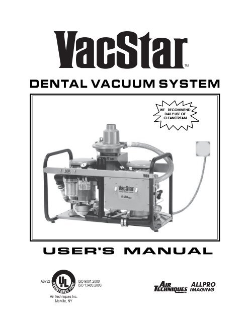
<strong>DENTAL</strong> <strong>VACUUM</strong> <strong>SYSTEM</strong><br />
WE RECOMMEND<br />
DAILY USE OF<br />
CLEANSTREAM<br />
USER'S MANUAL
CONGRATULATIONS ON YOUR PURCHASE<br />
OF THE VACSTAR <strong>DENTAL</strong> <strong>VACUUM</strong> <strong>SYSTEM</strong><br />
Your VacStar has been engineered to deliver maximum air flow at the ideal vacuum level without<br />
creating traumatic suction pressure that could harm patients’ delicate tissue. The VacStar is a water ring<br />
pump that produces consistent high-volume air flow, even with multiple users on-line. The balanced,<br />
corrosion free bronze impeller minimizes noise and a patented vacuum relief valve monitors and maintains<br />
constant uniform vacuum pressure. A capacitor-start type motor, with a highly reliable contactor and<br />
powerful transformer can be depended on to start every time. The VacStar is designed with everything<br />
accessible from the front, including the easy to clean solids collector.<br />
If your VacStar comes with an integral HydroMiser, water consumption will be reduced by up to 75%.<br />
If not, a HydroMiser can be integrated into your VacStar at a later date. The HydroMiser separates the<br />
liquid and gas discharge from the operatories. The gases are vented out and the liquid and its particulates<br />
are directed down the drain. The clean water extracted during this separation process is directed back<br />
toward the VacStar where it is mixed with fresh water and then directed into the pump chamber to create<br />
vacuum. This efficient reuse of water reduces the VacStar's fresh water consumption.<br />
Thousands of dentists have depended on the VacStar since 1987. Now that your practice has a VacStar,<br />
or a VacStar with the water saving HydroMiser, you too can depend on constant, uniform delivery of<br />
vacuum to your operatories and proven trouble-free operation.<br />
TABLE OF CONTENTS<br />
Sizing Guide . . . . . . . . . . . . . . . . . . . . . . . . . . . . . . . . . . . . . . . . . . . . 3<br />
Maintenance . . . . . . . . . . . . . . . . . . . . . . . . . . . . . . . . . . . . . . . . . . . . 3, 4<br />
Operating Information . . . . . . . . . . . . . . . . . . . . . . . . . . . . . . . . . . . . . . . . . . . 4<br />
Key Parts Identification . . . . . . . . . . . . . . . . . . . . . . . . . . . . . . . . . . .. . . . . . 4, 5<br />
Installation Information . . . . . . . . . . . . . . . . . . . . . . . . . . . . . . . . . . . . . . 6 - 8<br />
Trouble Shooting . . . . . . . . . . . . . . . . . . . . . . . . . . . . . . . . . . . . . . . . . 9<br />
Product Specifications/Dimensions . . . . . . . . . . . . . . . . . . . . . . . . . . . . . . . . 10<br />
Site Requirements . . . . . . . . . . . . . . . . . . . . . . . . . . . . . . . . . . . . . . . . . . 11<br />
Optional Accessories . . . . . . . . . . . . . . . . . . . . . . . . . . . . . . . . . . . . back cover<br />
Replacement/Reorder . . . . . . . . . . . . . . . . . . . . . . . . . . . . . . . . . . . . back cover<br />
2
SIZING GUIDE<br />
Choosing the correct size VacStar for your practice depends on the number of HVE (High Volume<br />
Evacuator) and SE (Saliva Ejector) users anticipated. To assure optimum vacuum, the vacuum demands<br />
should not exceed the number of HVE and SE users shown in the chart below:<br />
RECOMMENDED NUMBER OF SIMULTANEOUS USERS<br />
VacStar 20 VacStar 40 *VacStar 50 & 50H *VacStar 80 & 80H<br />
HVE’s + SE’s HVE’s + SE’s HVE’s + SE’s HVE’s + SE’s<br />
2 + 0 3 + 0 4 + 0 7 + 0<br />
1 + 1 2 + 2 3 + 2 6 + 1<br />
0 + 4 1 + 4 2 + 4 5 + 3<br />
0 + 6 1 + 5 4 + 4<br />
3 + 6<br />
2 + 8<br />
HVE - High Volume Evacuator SE - Saliva Ejector<br />
1 + 10<br />
0 + 13<br />
* These combinations apply if both pumps are running together.<br />
If only one pump is running, use the Sizing Guide for VacStar 20 or 40.<br />
MAINTENANCE<br />
! Daily Maintenance - Clean vacuum lines<br />
To maintain the cleanliness of your VacStar, including all the vacuum lines and tubing in your dental<br />
system, we recommend the daily use of CleanStream Evacuation System Cleaner. (see back cover)<br />
! Weekly Maintenance - Clean solids collector<br />
Caution: Solids collector may contain biologically<br />
hazardous material. Wear protective gloves.<br />
Note: Clean the solids collector DAILY during the<br />
first week of operation and during the first week of<br />
Evacuation System Cleaner usage.<br />
Fig. 1<br />
1. Use CleanStream Evacuation System Cleaner.<br />
2. Turn off the power and water supply.<br />
3. Unscrew the solids bowl (counter clock-wise) and<br />
remove the screen and gasket. Remove all the<br />
sediment build-up from the bowl, screen gasket and<br />
inside housing. Rinse thoroughly. See Fig.1.<br />
4. Reassemble the bowl, screen and gasket and screw<br />
tightly back onto the solids collector body or replace<br />
screen and bowl with Solids Collector Replacement<br />
Kit PN 55094 or PN 55880.<br />
Important: A worn or missing gasket and/or failure to tightly screw the bowl to the solids collector body<br />
will cause poor suction due to air leakage.<br />
DO NOT OPERATE THE VACSTAR WITHOUT THE SCREEN INSIDE THE FILTER BOWL.<br />
3
MAINTENANCE<br />
! In-Line Filter Kit<br />
If a VacStar is replacing a previous vacuum pump, an optional In-Line Filter, located in front of the<br />
inlet manifold (see Key Parts) is recommended. This In-Line Filter is designed to collect larger<br />
quantities of particulates from the discharge BEFORE it flows into the vacuum pump.<br />
Larger quantities of particulates may occur initially due to the VacStar's "pulling" power and to CleanStream<br />
Evacuation System Cleaner's ability to break down synthetic debris and proteinaceous deposits that build up<br />
in the vacuum lines. Check the filter daily and clean if required. In-Line Filter Kit for Single Vacuum Pumps<br />
#55078; for Twin Vacuum Pumps #55079.<br />
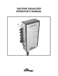
OPERATING INFORMATION<br />
! AT THE START OF THE DAY<br />
Always TURN ON THE WATER before TURNING ON THE POWER.<br />
! The VacStar may be turned on/off from a single, convenient location within the dental suite using a<br />
Remote Control Panel (See Optional Accessories).<br />
! The vacuum level is factory preset at 10 In Hg (inches of mercury). This is the reading on the gauge<br />
when all HVE’s (High Volume Evacuator) and SE’s (Saliva Ejector) are CLOSED. Should this setting<br />
be too high for your needs, contact your dealer to readjust the setting.<br />
! It is recommended that the system run continuously during the day. However, the VacStar can be turned off<br />
if suction is not required for a period of 15 minutes or longer.<br />
! If one pump is being operated at a time, it is important to alternate pumps on an every other day<br />
schedule so that the pumps are used evenly.<br />
! AT THE END OF THE DAY<br />
Always TURN THE POWER OFF, then TURN THE WATER OFF.<br />
KEY PARTS IDENTIFICATION - SINGLE UNITS<br />
Fig. 2<br />
<strong>VACUUM</strong><br />
RELIEF<br />
VALVE<br />
24 V<br />
REMOTE<br />
WIRING<br />
FUSE<br />
HOLDER<br />
MOTOR<br />
DRIP<br />
COVER<br />
INLET<br />
MANIFOLD<br />
MOTOR<br />
<strong>VACUUM</strong><br />
BREAKER<br />
<strong>VACUUM</strong><br />
GAUGE<br />
WATER<br />
INLET<br />
WATER<br />
SOLENOID<br />
INTAKE<br />
SOLIDS<br />
COLLECTOR<br />
ELECTRICAL<br />
JUNCTION<br />
BOX<br />
4<br />
WATER<br />
INLET<br />
FILTER
KEY PARTS IDENTIFICATION - TWIN UNITS<br />
Fig. 3 Front View<br />
<strong>VACUUM</strong><br />
RELIEF<br />
VALVE<br />
FRAME<br />
<strong>VACUUM</strong><br />
BREAKER<br />
HYDROMISER<br />
(ON VS50H AND<br />
VS80H ONLY)*<br />
VENT<br />
24 V<br />
REMOTE<br />
WIRING<br />
CONTROL<br />
BOX<br />
ELECTRICAL<br />
CONNECTION<br />
BOX<br />
<strong>VACUUM</strong><br />
GAUGE<br />
EXHAUST<br />
MANIFOLD<br />
INTAKE<br />
SOLIDS<br />
COLLECTOR<br />
LEVELING<br />
FEET<br />
WATER <strong>SYSTEM</strong><br />
CHECK VALVE<br />
BASE<br />
PLATE<br />
INLET<br />
MANIFOLD<br />
BYPASS<br />
EDUCTOR<br />
VALVE<br />
ASSEMBLY<br />
Fig. 3a<br />
MAIN<br />
POWER<br />
SWITCHES<br />
WATER<br />
SOLENOID<br />
Fig. 4 Close up of Eductor Assembly<br />
TO<br />
HYDROMISER<br />
WATER<br />
INLET<br />
CONNECTION<br />
WATER<br />
FILTER<br />
CIRCUIT<br />
BREAKER<br />
(FOR 24V<br />
REMOTE<br />
WIRING)<br />
WATER<br />
SOLENOID<br />
FRONT OF<br />
VACSTAR<br />
VACSTAR<br />
BASE PLATE<br />
CHECK<br />
VALVE<br />
TO LEFT<br />
PUMP<br />
TO RIGHT<br />
PUMP<br />
*VACSTAR 50H SHOWN - OTHER<br />
MODELS SIMILAR<br />
5
INSTALLATION INFORMATION<br />
! Plumbing (water) lines<br />
- To assure that the VacStar provides optimum vacuum, incoming water pressure must be maintained between<br />
20 and 100 psi.<br />
- If heavy combinations of particulates exist in the incoming water, an in-line filter should be installed. (See<br />
Accessories/Options for the Remote Control Water Valve.) This will prevent the VacStar's water inlet filter<br />
from clogging too frequently.<br />
- <strong>Inc</strong>oming water temperature should be between 40°F and 75°F.<br />
- Water connection location is shown in Fig. 2 and 3a (water inlet connection).<br />
! Suction<br />
- For VacStar 20 and 40, suction hose is connected at suction intake, found on intake solids collector assembly.<br />
See Fig. 2.<br />
- For VacStar twin pump units, suction hose is connected at suction intake, found on intake solids collector<br />
assembly. See Fig. 3.<br />
! Drain lines<br />
- For VacStar 20 and 40 without a HydroMiser or an <strong>Air</strong>/Water Separator, see Fig. 5.<br />
- For VacStars without a HydroMiser or an <strong>Air</strong>/Water Separator, the effluent should be discharged into an open<br />
drain or a closed vented drain. See Fig. 6.<br />
Note: For VacStars without HydroMiser, the drain may be up to 36" above the unit.<br />
Fig. 5 VacStar 20, 40 without a<br />
HydroMiser or <strong>Air</strong>/Water Separator<br />
Fig. 6 VacStar 50, 80 without a<br />
HydroMiser or <strong>Air</strong>/Water Separator<br />
DRAIN INSTALLATION<br />
closed<br />
vented<br />
drain<br />
or<br />
open<br />
drain<br />
pipe<br />
6
INSTALLATION INFORMATION<br />
- For VacStars with a HydroMiser (see Fig. 7) or an <strong>Air</strong>/Water Separator (see Fig. 8), gases should be vented<br />
out according to code. The waste water (with particulates) from the operatories can be discharged via an<br />
open drain or a closed vented drain.<br />
Fig. 7 VacStar with built-in HydroMiser<br />
VENT<br />
vent to outside with 2" schedule 40 pipe<br />
(WARNING: CONDENSATION OF WATER WILL<br />
OCCUR IN VENT PIPING. AVOID ACCUMULATION OF<br />
WATER IN VENT, SLOPE PIPING TOWARD SEPARATOR)<br />
HYDROMISER<br />
24<br />
VAC<br />
POWER<br />
CONNECTION<br />
WATER SUPPLY<br />
1/2" COPPER TUBE<br />
TERMINAL WITH<br />
1/2" FNPT SHUT<br />
OFF VALVE<br />
32" max.<br />
height<br />
Fig. 8 VacStar with wall mounted<br />
<strong>Air</strong>/Water Separator<br />
INTAKE FROM<br />
MAIN LINE<br />
terminate with<br />
1" FNPT fitting<br />
VENT<br />
vent to outside with 2" schedule 40 pipe<br />
(WARNING: CONDENSATION OF WATER WILL<br />
OCCUR IN VENT PIPING. AVOID ACCUMULATION<br />
OF WATER IN VENT, SLOPE PIPING TOWARD<br />
SEPARATOR)<br />
AIR/WATER<br />
SEPARATOR<br />
POWER<br />
CONNECTION<br />
24<br />
VAC<br />
WATER<br />
SUPPLY<br />
1/2" COPPER<br />
TUBE<br />
TERMINAL<br />
WITH<br />
1/2" FNPT<br />
SHUT<br />
OFF<br />
VALVE<br />
FLOOR SINK<br />
INTAKE FROM MAIN LINE - terminate with 1" FNPT fitting<br />
FLOOR SINK<br />
Note: VacStar 20, 40 installed in same manner<br />
DRAIN INSTALLATION<br />
closed<br />
vented<br />
drain<br />
or<br />
open<br />
drain<br />
pipe<br />
! Wall-mounted HydroMiser<br />
If the existing drain is higher than the HydroMiser outlet, the HydroMiser must be mounted so that its<br />
outlet is above the drain. The HydroMiser can be installed up to 36" above the base of the VacStar with<br />
the HydroMiser Wall Mount Kit (#55087).<br />
Fig. 9 VacStar with wall mounted Hydromiser<br />
IMPORTANT NOTE:<br />
ALL INSTALLATIONS<br />
VENT<br />
vent to outside with 2" schedule 40 pipe<br />
(WARNING: CONDENSATION OF WATER WILL<br />
OCCUR IN VENT PIPING. AVOID ACCUMULATION OF<br />
WATER IN VENT, SLOPE PIPING TOWARD SEPARATOR)<br />
Ambient temperature for all<br />
VacStar installations should be<br />
40°- 104°F (5°- 40°C).<br />
The liquid drain from the HydroMiser<br />
or an <strong>Air</strong>/Water Separator must<br />
slope downward at least 1/4" for<br />
every 10 feet of run toward the drain.<br />
(Avoid local low sections, avoid<br />
creating traps in the line.)<br />
HYDROMISER<br />
32" max.<br />
height<br />
POWER<br />
CONNECTION<br />
24<br />
VAC<br />
WATER<br />
SUPPLY<br />
1/2" COPPER<br />
TUBE<br />
TERMINAL<br />
WITH<br />
1/2" FNPT<br />
SHUT<br />
OFF<br />
VALVE<br />
FLOOR SINK<br />
7<br />
INTAKE FROM MAIN LINE - terminate with 1" FNPT fitting<br />
Note: VacStar 20, 40 installed in same manner
INSTALLATION INFORMATION<br />
! Electric<br />
- If the voltage is below the minimum 105V or 205V, a Boost Transformer must be installed. (See Product<br />
Specifications/Dimensions)<br />
- All VacStars must be wired directly from an electrical box that complies with local electrical codes to the<br />
VacStar’s Electrical Connection Box . See Fig. 10 for VacStar 20, 40; Fig. 11 for VacStar 50, 50H,<br />
80, 80H.<br />
FIG. 10 VACSTAR ELECTRICAL JUNCTION BOX - INTERIOR VIEW VacStar 20, 40<br />
WIRED FOR 230 V0LTS<br />
AT FACTORY<br />
FOR 230 V, JUMPER TABS ARE PLACED<br />
IN POSITION SHOWN (FACTORY SET)<br />
POWER SUPPLY<br />
CONNECTIONS<br />
2 - 3 5 - 6<br />
L1<br />
L2<br />
L1<br />
L2<br />
FOR 115 V, PLACE JUMPER TABS IN<br />
POSITION SHOWN<br />
1 - 2 3 - 4 6 - 7<br />
FIG. 11 VACSTAR<br />
ELECTRICAL CONNECTION BOX -VacStar 50, 50H, 80, 80H<br />
GREEN<br />
BLACK<br />
WHITE<br />
BLUE<br />
RED<br />
DUAL CIRCUIT<br />
PUMPS POWER<br />
LEADS<br />
RIGHT (L1) BLACK<br />
(L2) WHITE<br />
LEFT (L1) RED<br />
(L2) BLUE<br />
* For Single Circuit connect Black and Red wires<br />
together (L1) and White and Blue wires together (L2).<br />
8
PROBLEM POSSIBLE CAUSE POSSIBLE SOLUTIONS<br />
1. Low suction. a. Water filter or solids collector a. Clean filter and/or collector.<br />
clogged.<br />
b. Check valves are stuck. b. Use a system cleaner like CleanStream;<br />
turn vacuum on and off to free check<br />
valve. If valve remains stuck, call your<br />
authorized <strong>Air</strong> <strong>Techniques</strong> dealer for<br />
repair service.<br />
c. Low water pressure. c. Raise water pressure.<br />
d. HydroMiser water recycler is clogged. d. Open bypass valve to run VacStar.<br />
Call your authorized <strong>Air</strong> <strong>Techniques</strong><br />
dealer for repair service.<br />
e. HydroMiser clogged. e. Call your authorized <strong>Air</strong> <strong>Techniques</strong><br />
dealer for repair service.<br />
f. Solenoids not operating. f. Call your authorized <strong>Air</strong> <strong>Techniques</strong><br />
dealer for repair service.<br />
g. Restricted air exhaust g. Check air exhaust pipe size to make<br />
sure it conforms to spec; check for and<br />
clear possible restrictions in air exhaust<br />
system.<br />
2. No suction. a. Pumps off. a. Turn pumps on.<br />
b. Pumps not running. b. Call your authorized <strong>Air</strong> <strong>Techniques</strong><br />
dealer for repair service.<br />
c. Inlet check valves stuck closed. c. Call your authorized <strong>Air</strong> <strong>Techniques</strong><br />
dealer for repair service.<br />
d. Water inlet filter and/or d. Clean filter.<br />
Solids collector clogged.<br />
TROUBLE SHOOTING<br />
e. Suction hose collapsed. e. Hose needs to be replaced, call your<br />
authorized <strong>Air</strong> <strong>Techniques</strong> dealer for<br />
repair service.<br />
f. Solenoids not operating. f. Call your authorized <strong>Air</strong> <strong>Techniques</strong><br />
dealer for repair service.<br />
3. Excessive a. Relief valve stuck closed. a. Call your authorized <strong>Air</strong> <strong>Techniques</strong><br />
suction.<br />
dealer for repair service.<br />
b. Relief valve filter clogged. b. Call your authorized <strong>Air</strong> <strong>Techniques</strong><br />
dealer for repair service.<br />
4. Pumps do a. Main switches off. a. Turn main switches on.<br />
not run.<br />
b. Electrical problem. b. Call your authorized <strong>Air</strong> <strong>Techniques</strong><br />
dealer for repair service.<br />
5. Noisy a. Inadequate water supply. a. Call plumber to improve water<br />
Pumps.<br />
supply system.<br />
b. HydroMiser eductor clogged. b. Call your authorized <strong>Air</strong> <strong>Techniques</strong><br />
dealer for repair service.<br />
c. Drain line collapsed. c. Hose needs to be replaced. Call your<br />
authorized <strong>Air</strong> <strong>Techniques</strong> dealer<br />
for repair service.<br />
d. Solenoids not operating. d. Call your authorized <strong>Air</strong> <strong>Techniques</strong><br />
dealer for repair service.<br />
ALL INSTALLATIONS TO CONFORM TO LOCAL CODES<br />
9
PRODUCT SPECIFICATIONS/DIMENSIONS<br />
ELECTRICAL VS 20 VS 40 VS 50 VS 50H VS 80 VS 80H<br />
Voltage Rating *115/230 230 230 230 230 230<br />
Voltage<br />
Min./Max.<br />
*205/240<br />
*110/125 105<br />
205/240 205/240 205/240 205/240 205/240<br />
Full Load Amps *16/8 13.4 16 16 26.8 26.8<br />
WATER<br />
Inlet Water 20 - 100 20 - 100 20 - 100 20 - 100 20 - 100 20 - 100<br />
Pressure (PSI)<br />
Flow Rate Per Pump<br />
(gal/min)<br />
w / HydroMiser<br />
0.12 0.18 N/A 0.12 N/A 0.18<br />
Flow Rate Per Pump<br />
(gal/min)<br />
w/oHydroMiser<br />
0.50 0.75 0.50 N/A 0.75 N/A<br />
Water<br />
Temperature (°F) 40 - 75 40 - 75 40 - 75 40 - 75 40 - 75 40 - 75<br />
<strong>VACUUM</strong><br />
LEVEL<br />
Preset at Factory<br />
(In Hg)<br />
10 10 10 10 10 10<br />
SHIPPING<br />
WEIGHT (lbs)<br />
DIMENSIONS<br />
in. (HxWxD)<br />
68 85 160 170 200 210<br />
14 x 11x 11 17 x 11 x 11 22 x 28 x 16 25 x 28 x 16 22 x 28 16 25 x 28 x 16<br />
*VacStar 20 may be converted from 230 Volts to 115 Volts at installation site.<br />
10
SITE REQUIREMENTS<br />
ELECTRICAL VS 20 VS 40 VS 50 VS 50H VS 80 VS 80H<br />
Min. Circuit 2 ea. 20A 2 ea. 20A<br />
Breaker Rating 20A 20A 30A 30A or 1 ea. 40A or 1 ea. 40A<br />
Wire Size AWG 2 ea. 12 2 ea. 12<br />
(Min. Gauge)<br />
12 12 10 10<br />
or 1 ea. #8 or 1 ea. #8<br />
*Boost #67002(230V)<br />
#67002 #67002<br />
#67002 #67002 #67002<br />
Transformer #67500(115V)<br />
2 ea. 2 ea.<br />
PLUMBING VS 20 VS 40 VS 50 VS 50H VS 80 VS 80H<br />
Min.<br />
CFM 16 22 32 32 44 44<br />
@ 0" Hg<br />
<strong>Air</strong> Exhaust 2" schedule 2" schedule 2" schedule 2" schedule 2" schedule 2" schedule<br />
40 pipe 40 pipe 40 pipe 40 pipe 40 pipe 40 pipe<br />
Ambient 40° - 104°F 40° - 104°F 40° - 104°F 40° - 104°F 40° - 104°F 40° - 104°F<br />
Temperature (5°- 40°C) (5°- 40°C) (5°- 40°C) (5°- 40°C) (5°- 40°C) (5°- 40°C)<br />
Overhead<br />
Plumbing<br />
Main Line Dia.<br />
Min./Max ID 1 / 1½ 1¼ / 2 1¼ / 1½ 1¼ / 1½ 1½ / 2 1½ / 2<br />
in inches<br />
End Fitting<br />
Max<br />
1" FNPT 1" FNPT 1" FNPT 1" FNPT 1" FNPT 1" FNPT<br />
Riser Diameter<br />
Overhead Main ½” ID ½” ID ½” ID ½” ID ½” ID ½” ID<br />
Line<br />
Floor Plumbing<br />
Main Line Dia.<br />
Min./Max. ID 1 / 1½ 1¼ / 2 1¼ / 1½ 1¼ / 1½ 1½ / 2 1½ / 2<br />
in inches<br />
End Fitting<br />
Max<br />
3/4" FNPT 3/4" FNPT 1" FNPT 1" FNPT 1" FNPT 1" FNPT<br />
Branch Line Dia.<br />
Min./Max. ID 3/4 / 1½ 1 / 1½ 1 / 1½ 1 / 1½ 1 / 1½ 1 / 1½<br />
in inches<br />
NOTE: Suction piping must slope at least a ¼” for each 10 feet of run towards the pump.<br />
Use PVC Schedule 40 or Copper Type M.<br />
* Use Boost Transformer only if voltage is expected to fall below 105/205 Volts during operation.<br />
ALL INSTALLATIONS MUST CONFORM TO LOCAL CODES<br />
11
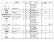
ACCESSORIES/OPTIONS<br />
DESCRIPTION MODEL PART NUMBER<br />
HydroMiser Wall Mount Kit VacStar 50H, 80H 55087<br />
Remote Control Panels VacStar 20, 40 53250 or 53251<br />
with 24V switches VacStar 50, 50H, 80, 80H 53113 or 53149<br />
Remote Control Water Valve, All VacStar Models 53020 (24V) - 3 4" pipe<br />
with filter<br />
53020-1 (115V) - 3 4" pipe<br />
53170 (24V) - 1" pipe<br />
53171 (115V) - 1" pipe<br />
Boost Transformer VacStar 20 67500 (115V)<br />
VacStar 20, 40, 50, 80<br />
67002 (230V)<br />
VacStar 80, 80H<br />
2 each 67002 (230V)<br />
HydroMiser Kit VacStar 20 H-2<br />
VacStar 40 H-4<br />
VacStar 50 56041<br />
VacStar 80 56042<br />
<strong>Air</strong>/Water Separator VacStar 20, 40, 50, 80 55540<br />
In-Line Filter Kit VacStar 20, 40 55078 - 3 4" pipe<br />
VacStar 50, 50H, 80, 80H 55079 - 1" pipe<br />
CleanStream Evacuation All VacStars 57660 Starter Kit<br />
System Cleaner<br />
57640 1 Box of 32 Packets<br />
REPLACEMENT/REORDER<br />
DESCRIPTION MODEL PART NUMBER<br />
Solids Collector VacStar 20, 40 55880<br />
Replacement Kit VacStar 50, 50H, 80, 80H 55094<br />
<strong>Air</strong> <strong>Techniques</strong> is a leading manufacturer of dental equipment from air compressors and vacuum systems to x-ray film<br />
processors, intraoral video cameras, and most recently air abrasion, rapid curing and bleaching and digital imaging<br />
systems. We have been manufacturing quality products for the dental professional since 1962.<br />
ACCENT TM<br />
Provecta 70 TM<br />
ACCLAIM ® ScanX ®<br />
<strong>Air</strong>Star ®<br />
SealX-2 TM<br />
A/T 2000 ® XR STS TM<br />
Peri-Pro ®<br />
VacStar TM<br />
Guardian TM Amalgam Collector<br />
100 Plus<br />
2010 Plus<br />
Medscope<br />
Provecta V<br />
ScanX ® 12<br />
ScanX ® 14<br />
ScanX ® DVM<br />
ScanX ® NDT<br />
ScanX ® 12 EV<br />
ScanX ® 14 PORTABLE<br />
ScanX ® NDT PORTABLE<br />
www.airtechniques.com<br />
1-800-AIR-TECH<br />
(1-800-247-8324)<br />
PN 55151 Rev. J<br />
VacStar is a trademark of <strong>Air</strong> <strong>Techniques</strong> <strong>Inc</strong>.<br />
© Copyright 2006 <strong>Air</strong> <strong>Techniques</strong> <strong>Inc</strong>.