Create successful ePaper yourself
Turn your PDF publications into a flip-book with our unique Google optimized e-Paper software.
Technical information<br />
<strong>Elastic</strong> <strong>element</strong> <strong>pressure</strong> <strong>gauges</strong><br />
WIKA data sheet IN 00.01<br />
Description<br />
Indicating <strong>pressure</strong> <strong>gauges</strong> with elastic measuring <strong>element</strong>s<br />
are used extensively to measure <strong>pressure</strong> in technical applications<br />
due to their robustness and ease-of-use. They incorporate<br />
measuring <strong>element</strong>s which deform elastically under<br />
the influence of <strong>pressure</strong>. Mechanical <strong>pressure</strong> <strong>gauges</strong> are<br />
produced with bourdon tube, diaphragm, capsule and spring<br />
<strong>element</strong>s and are differentiated as a result of these.<br />
The measuring <strong>element</strong>s are made of copper alloys, alloyed<br />
steels or, for specific measuring applications, produced in<br />
special materials. Pressures are only measurable in combination<br />
with a reference <strong>pressure</strong>. Atmospheric <strong>pressure</strong><br />
usually serves as the reference <strong>pressure</strong>, and the <strong>pressure</strong><br />
gauge therefore shows how much the measured <strong>pressure</strong> is<br />
higher or lower in relation to the given atmospheric <strong>pressure</strong><br />
(i.e. an over<strong>pressure</strong> measuring instrument).<br />
The <strong>pressure</strong> is indicated in standard measuring ranges<br />
over a 270 degree sweep on the dial. Liquid-filled <strong>pressure</strong><br />
<strong>gauges</strong>, due to their damping effect, offer optimal protection<br />
against damage from high dynamic <strong>pressure</strong> loads or vibrations.<br />
By combination with limit signal indicators, switching<br />
can be carried out, while in combination with transmitters,<br />
electrical output signals (e.g. 4 ... 20 mA) can be used for<br />
industrial process automation.<br />
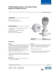
Pressure <strong>gauges</strong> with bourdon tube<br />
Bourdon tubes are circular-shaped tubes with an oval crosssection.<br />
The <strong>pressure</strong> of the media acts on the inside of this<br />
tube which results in the oval cross section becoming almost<br />
circular. Through the curvature of the tube, hoop stresses<br />
occur which bend the bourdon tube. The end of the tube,<br />
which is not fixed, moves, and this indicates the measurement<br />
for the <strong>pressure</strong>.<br />
Through the pointer movement this motion is indicated on the<br />
display. The circular-shaped tubes, formed through an angle<br />
of approx. 250°, are used for <strong>pressure</strong>s up to about 60 bar.<br />
The <strong>pressure</strong> ranges can be between 0 ... 0.6 and 0 ... 7000<br />
bar with a reading accuracy (or class) from 0.1 to 4.0 %.<br />
Pointer<br />
Bourdon tube<br />
End piece<br />
Link<br />
For higher <strong>pressure</strong>s, bourdon tubes are used with either<br />
a number of superimposed coils of the same diameter (i.e.<br />
helical coils), or a spiral-shaped coil (i.e. spiral springs) in a<br />
single plane.<br />
Bourdon tubes can only be protected against overload to a<br />
limited extent. In order to fulfil particularly harsh measuring<br />
tasks, the <strong>pressure</strong> gauge can be fitted with a chemical seal<br />
upstream as a separation or protection system.<br />
Dial<br />
Pressure entry<br />
Quadrant<br />
Movement<br />
Stem with <strong>pressure</strong><br />
connector<br />
Fig. Pressure <strong>gauges</strong> with bourdon tube<br />
WIKA data sheet IN 00.01 ∙ 09/2010<br />
Page 1 of 4
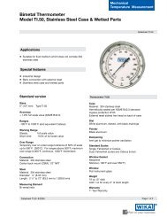
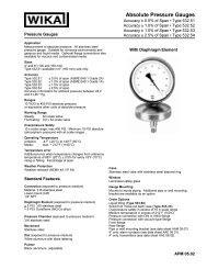
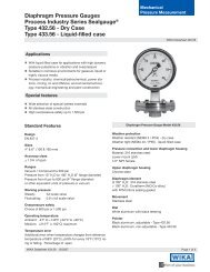
Pressure <strong>gauges</strong> with diaphragm <strong>element</strong>s<br />
Diaphragm <strong>element</strong>s are circular-shaped, corrugated<br />
membranes. They are either clamped around their rim<br />
between two flanges or welded and are subjected to the<br />
<strong>pressure</strong> of the media acting on one side. The deflection<br />
caused by this is used as a measurement for the <strong>pressure</strong><br />
and is indicated by a pointer.<br />
In comparison with bourdon tubes, these diaphragm <strong>element</strong>s<br />
have a relatively high actuating force and, as a result of the<br />
annular clamping of the <strong>element</strong>, they are insensitive to vibration.<br />
The diaphragm <strong>element</strong> can be subject to higher overload<br />
through the load take-up (diaphragm <strong>element</strong> resting against<br />
the upper flange), and by coating it with special material<br />
or covering it with foil, the gauge can be protected against<br />
extremely corrosive media.<br />
Dial<br />
Bolting<br />
Sealing<br />
ring<br />
Pressure entry<br />
Pointer<br />
Movement<br />
Link<br />
Upper diaphragm<br />
housing<br />
Diaphragm<br />
Bolting<br />
Lower diaphragm<br />
housing<br />
Pressure<br />
chamber<br />
For measurements with highly viscous, impure or crystallizing<br />
media, wide connection ports, open connection flanges and<br />
purging capabilities can be integrated.<br />
Fig. Pressure <strong>gauges</strong> with diaphragm <strong>element</strong>s<br />
Pressure ranges can be between 0 ... 16 mbar and 0 ... 40 bar<br />
with accuracy classes from 0.6 to 2.5.<br />
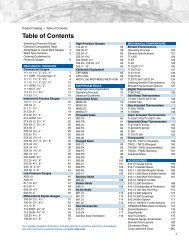
Pressure <strong>gauges</strong> with capsule <strong>element</strong>s<br />
The capsule <strong>element</strong> comprises two circular-shaped, corrugated<br />
membranes fully-sealed around their circumference.<br />
The <strong>pressure</strong> acts on the inside of this capsule and the stroke<br />
movement generated is indicated by a pointer as the measurement<br />
of <strong>pressure</strong>.<br />
Pressure <strong>gauges</strong> with capsule <strong>element</strong>s are particularly suited<br />
to gaseous media and relatively low <strong>pressure</strong>s. Overload<br />
protection is possible within certain limits. The actuating force<br />
is increased if a number of capsule <strong>element</strong>s are connected<br />
mechanically in series (a capsule <strong>element</strong> "package").<br />
Pressure<br />
chamber<br />
Capsule<br />
<strong>element</strong><br />
Stem with<br />
<strong>pressure</strong><br />
connector<br />
Dial<br />
Window<br />
Movement<br />
Pointer<br />
Pressure ranges can be between 0 ... 2.5 mbar and 0 ... 0.6 bar<br />
with accuracy classes of 0.1 to 2.5.<br />
Pressure entry<br />
Fig. Pressure <strong>gauges</strong> with capsule <strong>element</strong>s<br />
Page 2 of 4 WIKA data sheet IN 00.01 ∙ 09/2010
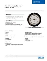
Absolute <strong>pressure</strong> <strong>gauges</strong><br />
These instruments are used where <strong>pressure</strong>s are to be<br />
measured independently of the natural fluctuations in atmospheric<br />
<strong>pressure</strong>. As a general rule, all the previously shown<br />
over<strong>pressure</strong> gauge <strong>element</strong>s and measuring principles can<br />
be applied.<br />
The <strong>pressure</strong> of the media to be measured is compared<br />
against a reference <strong>pressure</strong> which is equal to absolute zero.<br />
On the side of the measuring <strong>element</strong> that is not subjected to<br />
the <strong>pressure</strong> media, an absolute vacuum exists as the reference<br />
<strong>pressure</strong>. This function is achieved by sealing off the<br />
appropriate measuring chamber or surrounding housing.<br />
Measuring <strong>element</strong> movement transmission and <strong>pressure</strong><br />
indication are achieved in the same way as with the previously<br />
described over<strong>pressure</strong> <strong>gauges</strong>.<br />
Pressure ranges can be between 0 ... 25 mbar and 0 ... 25 bar<br />
with accuracy classes of 0.6 to 2.5.<br />
Sealed reference<br />
chamber (evacuated)<br />
Diaphragm<br />
<strong>element</strong><br />
Sealing<br />
bellows<br />
Link<br />
Sealing<br />
bellows<br />
Pressure<br />
chamber<br />
Pressure entry<br />
Fig. Absolute <strong>pressure</strong> <strong>gauges</strong><br />
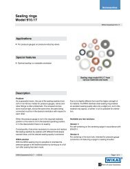
Differential <strong>pressure</strong> <strong>gauges</strong><br />
With differential <strong>pressure</strong> <strong>gauges</strong>, the difference between<br />
two <strong>pressure</strong>s is determined directly and shown on the<br />
display. Here again, all the previously shown over<strong>pressure</strong><br />
gauge measuring <strong>element</strong>s and measuring principles can be<br />
applied.<br />
Two sealed <strong>pressure</strong> media chambers are separated by the<br />
measuring <strong>element</strong>/s. If both operating <strong>pressure</strong>s are the<br />
same, no movement of the measuring <strong>element</strong> occurs and no<br />
<strong>pressure</strong> will be indicated. A differential <strong>pressure</strong> reading is<br />
only given when one of the <strong>pressure</strong>s is either higher or lower<br />
than the other.<br />
LP-<strong>pressure</strong><br />
chamber<br />
Diaphragm<br />
Link<br />
Sealing<br />
bellows<br />
Even with high static <strong>pressure</strong>s, low differential <strong>pressure</strong>s can<br />
be measured directly. With diaphragm <strong>element</strong>s, a very high<br />
overload capability is achieved.<br />
HP-<strong>pressure</strong><br />
chamber<br />
The permissible static <strong>pressure</strong> and the overload capability on<br />
the ⊕ and ⊖ side must be observed.<br />
In the majority of cases, measuring <strong>element</strong> movement transmission<br />
and <strong>pressure</strong> indication are achieved in the same way<br />
as with the previously described over<strong>pressure</strong> <strong>gauges</strong>.<br />
Pressure ranges can be between 0 ... 16 mbar and 0 ... 40 bar<br />
with accuracy classes of 0.6 to 2.5.<br />
Pressure p 1<br />
Pressure p 2<br />
Fig. Differential <strong>pressure</strong> <strong>gauges</strong><br />
Applications<br />
■■<br />
Filter technology (monitoring filter state)<br />
■■<br />
Level measurement (in closed vessels)<br />
■■<br />
Flow measurement (<strong>pressure</strong> drop)<br />
WIKA data sheet IN 00.01 ∙ 09/2010<br />
Page 3 of 4
The specifications given in this document represent the state of engineering at the time of publishing.<br />
We reserve the right to make modifications to the specifications and materials.<br />
Page 4 of 4 WIKA data sheet IN 00.01 ∙ 09/2010<br />
09/2010 GB<br />
WIKA Alexander Wiegand SE & Co. KG<br />
Alexander-Wiegand-Straße 30<br />
63911 Klingenberg/Germany<br />
Tel. (+49) 9372/132-0<br />
Fax (+49) 9372/132-406<br />
E-mail info@wika.de<br />
www.wika.de