Optimization of a Cost-Effective âWire-Plateâ Type ESP for ...
Optimization of a Cost-Effective âWire-Plateâ Type ESP for ...
Optimization of a Cost-Effective âWire-Plateâ Type ESP for ...

Create successful ePaper yourself
Turn your PDF publications into a flip-book with our unique Google optimized e-Paper software.
60 cm<br />
Control circuit<br />
45 cm<br />
Input voltage<br />
220 AC<br />
Step-down<br />
Trans<strong>for</strong>mer<br />
220/24 V<br />
Rectifier bridge<br />
100<br />
cm<br />
Voltage<br />
Regulator<br />
LM7815<br />
NE555 Timer<br />
Mosfets driver<br />
UCC37322<br />
Power stage<br />
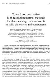
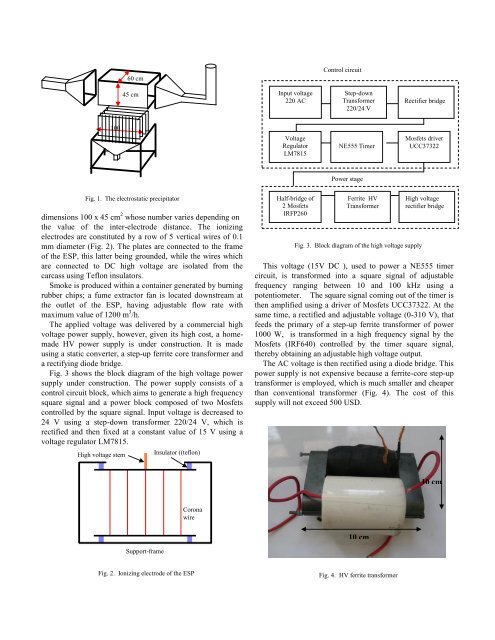
Fig. 1. The electrostatic precipitator<br />
dimensions 100 x 45 cm 2 whose number varies depending on<br />
the value <strong>of</strong> the inter-electrode distance. The ionizing<br />
electrodes are constituted by a row <strong>of</strong> 5 vertical wires <strong>of</strong> 0.1<br />
mm diameter (Fig. 2). The plates are connected to the frame<br />
<strong>of</strong> the <strong>ESP</strong>, this latter being grounded, while the wires which<br />
are connected to DC high voltage are isolated from the<br />
carcass using Teflon insulators.<br />
Smoke is produced within a container generated by burning<br />
rubber chips; a fume extractor fan is located downstream at<br />
the outlet <strong>of</strong> the <strong>ESP</strong>, having adjustable flow rate with<br />
maximum value <strong>of</strong> 1200 m 3 /h.<br />
The applied voltage was delivered by a commercial high<br />
voltage power supply, however, given its high cost, a homemade<br />
HV power supply is under construction. It is made<br />
using a static converter, a step-up ferrite core trans<strong>for</strong>mer and<br />
a rectifying diode bridge.<br />
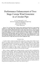
Fig. 3 shows the block diagram <strong>of</strong> the high voltage power<br />
supply under construction. The power supply consists <strong>of</strong> a<br />
control circuit block, which aims to generate a high frequency<br />
square signal and a power block composed <strong>of</strong> two Mosfets<br />
controlled by the square signal. Input voltage is decreased to<br />
24 V using a step-down trans<strong>for</strong>mer 220/24 V, which is<br />
rectified and then fixed at a constant value <strong>of</strong> 15 V using a<br />
voltage regulator LM7815.<br />
High voltage stem<br />
Insulator ((teflon)<br />
Half-bridge <strong>of</strong><br />
2 Mosfets<br />
IRFP260<br />
Ferrite HV<br />
Trans<strong>for</strong>mer<br />
Fig. 3. Block diagram <strong>of</strong> the high voltage supply<br />
High voltage<br />
rectifier bridge<br />
This voltage (15V DC ), used to power a NE555 timer<br />
circuit, is trans<strong>for</strong>med into a square signal <strong>of</strong> adjustable<br />
frequency ranging between 10 and 100 kHz using a<br />
potentiometer. The square signal coming out <strong>of</strong> the timer is<br />
then amplified using a driver <strong>of</strong> Mosfets UCC37322. At the<br />
same time, a rectified and adjustable voltage (0-310 V), that<br />
feeds the primary <strong>of</strong> a step-up ferrite trans<strong>for</strong>mer <strong>of</strong> power<br />
1000 W, is trans<strong>for</strong>med in a high frequency signal by the<br />
Mosfets (IRF640) controlled by the timer square signal,<br />
thereby obtaining an adjustable high voltage output.<br />
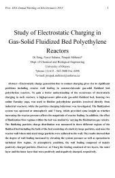
The AC voltage is then rectified using a diode bridge. This<br />
power supply is not expensive because a ferrite-core step-up<br />
trans<strong>for</strong>mer is employed, which is much smaller and cheaper<br />
than conventional trans<strong>for</strong>mer (Fig. 4). The cost <strong>of</strong> this<br />
supply will not exceed 500 USD.<br />
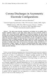
10 cm<br />
Corona<br />
wire<br />
10 cm<br />
Support-frame<br />
Fig. 2. Ionizing electrode <strong>of</strong> the <strong>ESP</strong><br />
Fig. 4. HV ferrite trans<strong>for</strong>mer