Study of Laser Ablation and Mechanical Properties of Silicone ...
Study of Laser Ablation and Mechanical Properties of Silicone ...
Study of Laser Ablation and Mechanical Properties of Silicone ...
- No tags were found...

You also want an ePaper? Increase the reach of your titles
YUMPU automatically turns print PDFs into web optimized ePapers that Google loves.
Proc. ESA Annual Meeting on Electrostatics 2008, Paper B3 1<strong>Study</strong> <strong>of</strong> <strong>Laser</strong> <strong>Ablation</strong> <strong>and</strong> <strong>Mechanical</strong><strong>Properties</strong> <strong>of</strong> <strong>Silicone</strong> Rubber NanocompositesIsaias Ramirez 1,2 , Shesha Jayaram 1 , Edward A. Cherney 1 ,Mario Gauthier 11 University <strong>of</strong> Waterloo200 University Ave. WestWaterloo, Ontario, Canada, N2L 3G1e-mail: i2ramire@uwaterloo.ca2 Instituto de Investigaciones EléctricasReforma 113, Col PalmiraCuernavaca, Morelos, México 62490Abstract— The use <strong>of</strong> nan<strong>of</strong>illers has increased significantly in many fields during the lastfew years with the growing interest in nanotechnology applications. In this paper nanocompositeswith different amounts <strong>of</strong> surfactant <strong>and</strong> fillers were studied to determine the tensileproperties <strong>of</strong> nan<strong>of</strong>illed samples. The results obtained show that it is essential to optimize theamount <strong>of</strong> surfactant used as otherwise the mechanical properties <strong>of</strong> the composites are negativelyimpacted in terms <strong>of</strong> reduced hardness <strong>and</strong> lowered tensile strength. An optimalamount <strong>of</strong> surfactant does not affect significantly the above-mentioned mechanical properties,however. In addition, laser ablation tests were done using a near infrared laser beam toassess the erosion resistance <strong>of</strong> all the samples. The laser tests confirmed that composites containingnano fumed silica have enhanced resistance to erosion as compared to natural nanosilica or nanoalumina-filled composites.I. INTRODUCTIONPolymeric nanocomposites have attracted considerable attention over recent years. Inparticular, use <strong>of</strong> nanoparticles can lead to enhanced electrical <strong>and</strong> mechanical propertieswhen incorporated in a s<strong>of</strong>t matrix, due to the large number <strong>of</strong> interacting <strong>and</strong>/or crosslinkingsites at the nanoparticle-matrix inter-face. Improvements in the materials’ propertiescan only be achieved if the filler is well dispersed into the rubber matrix, however. Ina previous study it was shown that a commercial surfactant could improve the dispersion<strong>of</strong> nan<strong>of</strong>illers in silicone rubber [1]. The level <strong>of</strong> matrix reinforcement achieved also dependson the extent <strong>of</strong> interaction between the organic <strong>and</strong> inorganic phases.Reinforcing inorganic micro fillers such as alumina or silica is an important componentto improve the performance <strong>of</strong> a silicone rubber matrix for outdoor insulation applica-
Proc. ESA Annual Meeting on Electrostatics 2008, Paper B3 2tions. It has been proposed that the reinforcement is due to the interactions <strong>of</strong> polymerchains with the filler surface through Van der Waals forces, hydrogen bonding, <strong>and</strong>/or bycovalent bonding [2].In the current investigation, different nan<strong>of</strong>illers were examined to reinforce siliconerubber for outdoor insulation applications in power systems. The inter-facial interactionbetween the silicone rubber matrix <strong>and</strong> the inorganic filler plays a key role in the reinforcementeffect; another important point to consider is the particle size [3]. The addition<strong>of</strong> fillers results in improved tracking resistance, erosion resistance, <strong>and</strong> mechanicalstrength <strong>of</strong> the composite material.To achieve good dispersion <strong>of</strong> the fillers in the nanocomposites, the commercial surfactantTriton X-100 was used. While better dispersion <strong>of</strong> the nan<strong>of</strong>iller improves the erosionresistance <strong>of</strong> the silicone, the surfactant also introduces another interface betweenthe filler <strong>and</strong> the silicone matrix. It is, consequently, essential to optimize the amount <strong>of</strong>surfactant used to avoid any negative impact on the mechanical properties <strong>of</strong> the composite.The nature <strong>of</strong> the filler-matrix interface can affect properties such as the tensilestrength, elongation at break, <strong>and</strong> hardness <strong>of</strong> the material.Composites with different amounts <strong>of</strong> surfactant <strong>and</strong> fillers were investigated to determinethe influence <strong>of</strong> nan<strong>of</strong>illers on the tensile properties <strong>and</strong> the ablation resistance <strong>of</strong>the samples.II. METHODOLOGYA. Materials <strong>and</strong> Sample PreparationIn this research nano fumed silica, natural nano silica, nanoalumina, <strong>and</strong> microsilicawere used as fillers. The main characteristics <strong>of</strong> these materials are summarized in Table1. The matrix is a two-part addition cure silicone rubber RTV 615 (SiR) manufactured bythe General Electric Company. The surfactant Triton X-100 TM was used to improve thedispersion <strong>of</strong> the nan<strong>of</strong>illers.A Ross model HSM-100LSK mixer with a high shear force was used to disperse theparticles uniformly within the silicone rubber matrix. For most industrial applications,Degussa [4] suggests tip speeds (peripheral velocities) ranging from 8-10 m/sec toachieve adequate particle dispersion. For the Ross mixer, this corresponds to a mixingspeed between 9550 <strong>and</strong> 11935 rpm. The wet-in time is defined as the time required forall the nanoparticles to be wetted by the dispersion medium; at this stage a low mixingspeed was used (6,000 rpm). Once the nanoparticles were wetted, the mixing speed wasincreased to 12,000 rpm to begin dispersion. For samples with surfactant, the siliconerubber (SiR) was mixed with the surfactant prior to adding the nan<strong>of</strong>iller [1].The samples were cured at room temperature for 24 h <strong>and</strong> then post-cured in an ovenat 87ºC for 4 h.
Proc. ESA Annual Meeting on Electrostatics 2008, Paper B3 3TABLE 1: CHARACTERISTICS OF THE FILLERSFillers usedAverage particlesize (nm)Surface area(m 2 /g, BET*)Density(g/mL)@25 ºCNano fumed silica 7 390±40 2.2Nano alumina 2-4 350-720 4Natural nanosilica 10 590-690 2.2-2.6Microsilica 5000 5 0.58* In honor <strong>of</strong> S. Brunauer, P. H. Emmett, <strong>and</strong> E. TellerSamples were prepared with different compositions <strong>of</strong> nan<strong>of</strong>iller <strong>and</strong> a fixed amount <strong>of</strong>micr<strong>of</strong>iller. Calcination for one hour at a temperature <strong>of</strong> 300°, 600°, or 900°C was usedto break-up aggregates <strong>and</strong> pellets <strong>of</strong> nan<strong>of</strong>illers, <strong>and</strong> to eliminate adsorbed water [5].For the laser test, the samples require a darker color to ensure identical spectral absorption<strong>of</strong> the laser radiation; this was achieved by including 2.5% wt <strong>of</strong> iron oxide inthe mixture for all samples. Since Fe 2 O 3 is stable at high temperatures, above the decompositiontemperature <strong>of</strong> the SiR matrix, it may be considered otherwise inert [6].B. Eroded Mass AssessmentIn the evaluation <strong>of</strong> the eroded mass <strong>of</strong> nanocomposites under the influence <strong>of</strong> dryb<strong>and</strong> arcing, a method that has been shown to give results equivalent to the inclinedplane test is the laser erosion test developed by Meyer et al. [7]. Heat from dry b<strong>and</strong> arcingis the main degradation factor in the use <strong>of</strong> SiR in outdoor insulation; consequently,the degradation is thermal <strong>and</strong> the laser test can be used to simulate the effects <strong>of</strong> dryb<strong>and</strong> arcing. The eroded mass evaluation was conducted to differentiate between the differentfilled materials.The method consists <strong>of</strong> delivering the same energy to each sample; in this case a Coherentmodel FAP infrared laser with an operating wavelength <strong>of</strong> 802 nm was used. Theheat produces molecular vibrations causing the polymer to breakdown. Several tests wereconducted to adjust the diode laser, which was operated in the continuous wave (CW)mode with a current <strong>of</strong> 17.5 A (power equivalent to 8.8 W) for 7 minutes (the calculatedenergy dose equals 3700 Joules). The sample was located 5 cm away from the lasersource in all the tests.The eroded mass <strong>of</strong> the samples was determined from the weight measured before <strong>and</strong>after testing using a Sartorius AC 211S-00MS balance with a readability <strong>of</strong> 0.1 mg. Foreach sample, 3 tests were carried out. The average <strong>of</strong> the 3 eroded mass values is representedin the plots.
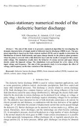
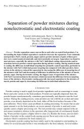
Proc. ESA Annual Meeting on Electrostatics 2008, Paper B3 4C. <strong>Mechanical</strong> TestsStress–strain measurements were done at room temperature in the uniaxial extensionmode <strong>and</strong> along the direction <strong>of</strong> increasing elongation. The tensile tester, a Minimat2000, was used following the procedure described in ASTM D1708. For each formulation,5 to 10 samples were tested. The testing speed was 100 mm/min (speed D) [8]. Thestress, σ, was calculated as:fσ =(1)A 0where f <strong>and</strong> A 0 are the measured force <strong>and</strong> the initial cross-sectional area, respectively.The hardness was measured according to the ASTM D2240 st<strong>and</strong>ard [9] using a durometerModel 408 ASTM type A for applications in s<strong>of</strong>t rubbers, elastomers, <strong>and</strong> flexiblepolyacrylics. Following the st<strong>and</strong>ard, 5 measurements were recorded for each sample<strong>and</strong> the mean <strong>and</strong> the st<strong>and</strong>ard deviation were reported. The objective <strong>of</strong> these tests wasto evaluate the behavior after adding surfactant to the samples.III. RESULTS AND DISCUSSIONA. Eroded mass <strong>of</strong> nan<strong>of</strong>illed specimens using laser testThree samples at each composition consisting <strong>of</strong> either 2.5 or 5 wt % <strong>of</strong> nan<strong>of</strong>iller <strong>and</strong>various Triton additions (expressed in parts per hundred, pph, <strong>of</strong> nan<strong>of</strong>iller by weight)were tested. Each point in Figures 1 <strong>and</strong> 2 corresponds to the average eroded mass forthree samples at the different Triton concentrations.5505002.5% nfs2.5% nS2.5% Al2O3450Eroded mass (mg)4003503002502001500 20 40 60 80 100Triton addition by weight in pph <strong>of</strong> nan<strong>of</strong>illerFigure 1: Eroded mass <strong>of</strong> samples with 2.5 wt % <strong>of</strong> different nano fillers for various Triton additions (in pph <strong>of</strong>nan<strong>of</strong>iller). Each data point shown is the average <strong>of</strong> three samples at each Triton concentration.
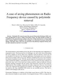
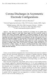
Proc. ESA Annual Meeting on Electrostatics 2008, Paper B3 635020%m+% nfs20% m+ % nfs+ 14 pph T20% m + % nfs+ 28 pphT300Eroded mass (mg)2502001501.25% 2.5% 3.75% 5%% <strong>of</strong> nano fumed silicaFigure 3: Average eroded mass <strong>of</strong> three samples with 20 % microsilica filler (m) for various additions <strong>of</strong> nan<strong>of</strong>umed silica (nfs) <strong>and</strong> Triton (expressed in parts per hundred, pph, <strong>of</strong> nan<strong>of</strong>iller by weight).The eroded mass observed in laser ablation tests using calcinated fillers is shown inFigure 4 for several fillers <strong>and</strong> as a function <strong>of</strong> Triton content. It appears that calcinationdoes not have as much influence on the eroded mass as the addition <strong>of</strong> Triton, <strong>and</strong> all theresults tend to converge when adding 28 pph <strong>of</strong> Triton.In these tests it was noticed that for the 2.5% nfs content treated at 900°C, a whitelayer developed in the sample during the test. As shown in Figure 5, this is likely to be alayer <strong>of</strong> silica formation; <strong>and</strong> such a protective mechanism decreasing sample erosion hasbeen reported previously [11].The decomposition <strong>of</strong> SiR in air is known to produce white silica particles [12]. Thewhite layer is therefore attributed to filler residues <strong>and</strong> to the decomposition <strong>of</strong> the SiRmatrix in air. For this reason, samples with 2.5% nfs thermally treated at 900°C were notevaluated by the laser technique, because the laser beam is likely reflected by the whitelayer, biasing the erosion level determined by laser ablation. It appears likely that thissilica layer also forms a heat-resistant shield hindering further heat ablation <strong>of</strong> the underlyingSiR matrix.
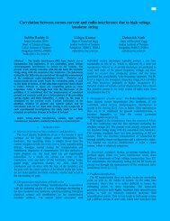
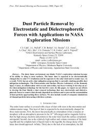
Proc. ESA Annual Meeting on Electrostatics 2008, Paper B3 750045020%m+2.5% nfs (300°C)20%m+2.5% nfs (600°C)Eroded mass (mg)40035030025020%m+2.5% nfs (900°C)2.5% nfs (300°C)2.5% nfs (600°C)2001500 pphT 14 pph T 28 pph TTriton Concentration in pphFigure 4: Average eroded mass <strong>of</strong> three samples with 20 % microsilica filler (m) <strong>and</strong> for 2.5 % nano size fumedfiller (nfs) calcinated at different temperatures <strong>and</strong> for various Triton additions (expressed in parts per hundred,pph, <strong>of</strong> nan<strong>of</strong>iller by weight).(a)(b)Figure 5: Eroded samples (a) with normal charred surface <strong>and</strong> after the char was removed (b) with the formation<strong>of</strong> a white silica layer.C. <strong>Mechanical</strong> TestsThe tensile strength, elongation at break, <strong>and</strong> hardness are bulk properties <strong>of</strong> siliconethat are affected by the type <strong>and</strong> amount <strong>of</strong> filler particles, <strong>and</strong> their interactions (bonding)with the polymer matrix. Since the addition <strong>of</strong> surfactant to disperse the filler canhave adverse effects on bonding, the mechanical properties may be negatively impacted.In Figure 6 the ultimate tensile strength is shown for the samples combining nan<strong>of</strong>umed silica <strong>and</strong> microsilica (m+nfs) for several surfactant concentrations.
Proc. ESA Annual Meeting on Electrostatics 2008, Paper B3 8Although the tensile strength is somewhat higher for the micro- <strong>and</strong> nan<strong>of</strong>illed samplesas compared to the nfs-filled samples, it is evident that the addition <strong>of</strong> 14 pph <strong>of</strong> surfactanthas little effect on the tensile strength. A lower decrease is observed in samples with28 pph surfactant. For these samples, a maximum reduction in the average tensilestrength by about 4% was found with respect to the samples without surfactant. Although,28 pph <strong>of</strong> surfactant is considered to be high <strong>and</strong> above that needed, 14 pph, forproper dispersion <strong>of</strong> the nan<strong>of</strong>illers, it seems that both concentrations can be used withouta significant decrease in tensile strength [10]. The actual values <strong>of</strong> average tensilestrength obtained are summarized in Table 2.The hardness <strong>and</strong> elongation at break <strong>of</strong> the filled samples are also compared in Table2. The variations observed in both parameters are similar to the tensile strength. Hence,it can be stated that for an addition <strong>of</strong> 14 pph surfactant, the mechanical properties areunaffected.2500Ultimate tensile strength (kPa)2000150010002.5% nfs2.5% nfs+14 pphT2.5% nfs+28 pphT20%m+2.5%nfs20%m+2.5%nfs+14 pphT20%m+2.5%nfs+28 pphTSampleFigure 6: Ultimate tensile strength <strong>of</strong> nan<strong>of</strong>illed <strong>and</strong> micro-nan<strong>of</strong>illed samples, discontinuous line shows theaverage.
Proc. ESA Annual Meeting on Electrostatics 2008, Paper B3 9SampleTABLE 2: SUMMARY OF MECHANICAL EVALUATIONUltimate tensilestrength(kPa)St<strong>and</strong>arddeviationElongation(%)Hardness(Type A)2.5% nfs 1112.3 165.8 238.5 51.52.5% nfs+14 pphT2.5% nfs+28 pphT20%m+2.5%nfs20%m+2.5%nfs+14 pphT20%m+2.5%nfs+28 pphT1120.0 280.1 235.4 50.3989.0 138.0 219.2 50.02385.0 222.3 213.6 61.92339.2 198.3 209.4 60.92311.8 343.9 226.5 57.6IV. CONCLUSIONSThe laser ablation tests were done using a near infrared laser beam to assess the erosionresistance <strong>of</strong> silica-filled samples. Fumed silica was shown to impart greater heat ablationresistance than either natural silica or alumina. There was no significant difference in theerosion resistance <strong>of</strong> natural silica- or alumina-filled compositions. The ablation observedfor nanosilica-filled specimens suggests that the silica accumulated at the surfaceforms a heat-resistant barrier preventing further erosion <strong>of</strong> the underlying silicone rubber.The results obtained demonstrated that the amount <strong>of</strong> surfactant does not decrease significantlythe tensile strength, elongation at break, <strong>and</strong> hardness <strong>of</strong> the filled samples.ACKNOWLEDGMENTSThe authors thank the Natural Sciences <strong>and</strong> Engineering Research Council <strong>of</strong> Canada forfinancial support. Isaias Ramirez gratefully acknowledges the Instituto de InvestigacionesElectricas for a study leave <strong>and</strong> the Mexican Science Council (CONACYT) forfinancial support <strong>of</strong> his graduate studies. Thanks are due to Dr. Juan Francisco PerezRobles from CINVESTAV-Queretaro for his useful comments <strong>and</strong> advice.
Proc. ESA Annual Meeting on Electrostatics 2008, Paper B3 10REFERENCES[1] Isaias Ramirez, Shesha Jayaram, Edward A. Cherney, <strong>and</strong> Mario Gauthier, “Improving the dispersion <strong>of</strong>nan<strong>of</strong>illers in silicone polymers by surface treatment”, Proceedings <strong>of</strong> the ESA Annual Meeting on Electrostatics,West Lafayette, Indiana, USA, June12-14, 2007.[2] James S. Smith, Oleg Borodin, Grant D. Smith, Edward M. Kober, “A Molecular Dynamics Simulation<strong>and</strong> Quantum Chemistry <strong>Study</strong> <strong>of</strong> Poly(dimethylsiloxane)–Silica Nanoparticle Interactions”, Journal <strong>of</strong>Polymer Science: Part B: Polymer Physics, Volume 45, pp. 1599–1615, 2007.[3] Ludivine Dewimille, B. Bresson, L. Bokobza, “Synthesis, structure <strong>and</strong> morphology <strong>of</strong>poly(dimethylsiloxane) networks filled with in situ generated silica particles”, Polymer Volume 46, pp4135–4143, 2005.[4] Degussa, “Successful Use <strong>of</strong> AEROSIL® Fumed Silica in Liquid Systems”, Technical Information No.1279, March 2006.[5] Wladyslaw W. Kubiak, Ewa Niewiara, “Influence <strong>of</strong> the Electrolyte on Triton X-100 Adsorption onFumed Silica”, Electroanalysis 2002, Volume 14, No.17, WILEY-VCH.[6] Malcom J. Billings, Leonard Warren, <strong>and</strong> Robert Wilkins, “Thermal Erosion <strong>of</strong> Electrical Insulating Materials”,IEEE Transactions on Electrical Insulation Volume 6, No. 2, June 1971.[7] Luiz H. Meyer, Shesha H. Jayaram, <strong>and</strong> Edward A.Cherney, “A Novel Technique to Evaluate the ErosionResistance <strong>of</strong> <strong>Silicone</strong> Rubber Composites for High Voltage Outdoor Insulation Using Infrared <strong>Laser</strong> Erosion”,IEEE Transactions on Dielectrics <strong>and</strong> Electrical Insulation Volume 12, No. 6, December 2005.[8] ASTM D 1708-06a, “St<strong>and</strong>ard Test Method for Tensile <strong>Properties</strong> <strong>of</strong> Plastics by Use <strong>of</strong> MicrotensileSpecimens”, ASTM International, 2006.[9] ASTM D 2240-05, “St<strong>and</strong>ard Test Method for Rubber Property - Durometer Hardness”, ASTM International2005.[10] Isaias Ramirez, Edward A. Cherney, Shesha Jayaram, <strong>and</strong> Mario Gauthier, “Nan<strong>of</strong>illed <strong>Silicone</strong> DielectricsPrepared with Surfactant for Outdoor Insulation Applications”, IEEE Transactions on Dielectrics <strong>and</strong>Electrical Insulation Vol. 15, No. 1; pages 228-235, February 2008.[11] T. Kashiwagi, J. W. Gilman, K. M. Butler, R. H. Harris, J. R. Shields, <strong>and</strong> A. Asano, “Flame RetardantMechanism <strong>of</strong> Silica Gel/Silica”, Fire <strong>and</strong> Materials Volume 24, pp. 277-289, 2000.[12] G. Camino, S. M. Lomakin <strong>and</strong> M. Lazzari, “Polydimethylsiloxane thermal degradation Part 1. Kineticaspects”, Polymer, Volume 42, pp. 2395–2402, 2001.