Turbonetics 350Z Turbo Kit Installation Manual 15134-t.pdf
Turbonetics 350Z Turbo Kit Installation Manual 15134-t.pdf
Turbonetics 350Z Turbo Kit Installation Manual 15134-t.pdf

Create successful ePaper yourself
Turn your PDF publications into a flip-book with our unique Google optimized e-Paper software.
You can purchase this part at: http://thmotorsports.com<br />
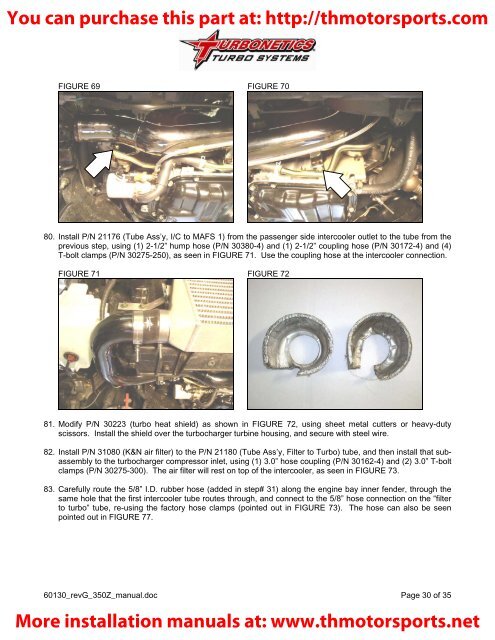
FIGURE 69 FIGURE 70<br />
80. Install P/N 21176 (Tube Ass’y, I/C to MAFS 1) from the passenger side intercooler outlet to the tube from the<br />
previous step, using (1) 2-1/2” hump hose (P/N 30380-4) and (1) 2-1/2” coupling hose (P/N 30172-4) and (4)<br />
T-bolt clamps (P/N 30275-250), as seen in FIGURE 71. Use the coupling hose at the intercooler connection.<br />
FIGURE 71 FIGURE 72<br />
81. Modify P/N 30223 (turbo heat shield) as shown in FIGURE 72, using sheet metal cutters or heavy-duty<br />
scissors. Install the shield over the turbocharger turbine housing, and secure with steel wire.<br />
82. Install P/N 31080 (K&N air filter) to the P/N 21180 (Tube Ass’y, Filter to <strong>Turbo</strong>) tube, and then install that subassembly<br />
to the turbocharger compressor inlet, using (1) 3.0” hose coupling (P/N 30162-4) and (2) 3.0” T-bolt<br />
clamps (P/N 30275-300). The air filter will rest on top of the intercooler, as seen in FIGURE 73.<br />
83. Carefully route the 5/8” I.D. rubber hose (added in step# 31) along the engine bay inner fender, through the<br />
same hole that the first intercooler tube routes through, and connect to the 5/8” hose connection on the “filter<br />
to turbo” tube, re-using the factory hose clamps (pointed out in FIGURE 73). The hose can also be seen<br />
pointed out in FIGURE 77.<br />
60130_revG_<strong>350Z</strong>_manual.doc Page 30 of 35<br />
More installation manuals at: www.thmotorsports.net