P82623 - Wheelock Products
P82623 - Wheelock Products
P82623 - Wheelock Products

You also want an ePaper? Increase the reach of your titles
YUMPU automatically turns print PDFs into web optimized ePapers that Google loves.
273 Branchport Avenue<br />
Long Branch, NJ 07740<br />
(800) 631-2148<br />
www.wheelockinc.com<br />
Thank you for using our products.<br />
INSTALLATION INSTRUCTIONS<br />
AMT MULTITONE APPLIANCES<br />
AMT-12/24<br />
Use this product according to this instruction manual. Please keep this instruction manual for future reference.<br />
GENERAL:<br />
AMT Multitone Appliances are UL Listed for Fire Protective Service, General Signaling Service and UL Standard 464 for Audible<br />
Signal Appliances. They are listed for both indoor and outdoor use with the backboxes specified in these instructions. (See Mounting<br />
Options A,B,C,D,E,F,G). <strong>Wheelock</strong>'s AMT Appliances are unique multitone alarm appliances with separate input terminals for each<br />
sound. They are the ideal choice for Halon Protection Systems and emergency signaling systems where distinctive multiple alarm<br />
conditions are required. Eight groups of three self-prioritized sound outputs are provided with separate electrically isolated input<br />
terminals for each sound (see Table 2 and 4 for sound selections). Sound output can be field set to provide either HIGH (HI) dBA or<br />
STANDARD (STD) dBA sound output level. AMT Multitone Appliances can be field set for either 12VDC or 24VDC operation and<br />
are designed for use with either filtered or unfiltered (full-wave-rectified) input voltage. All inputs are polarized for compatibility<br />
with standard reverse supervision of circuit wiring by Fire Alarm Control Panel (FACP).<br />
NOTE: All CAUTIONS and WARNINGS are identified by the symbol . All warnings are printed in bold capital letters.<br />
WARNING: PLEASE READ THESE INSTRUCTIONS CAREFULLY BEFORE USING THIS PRODUCT. FAILURE<br />
TO COMPLY WITH ANY OF THE FOLLOWING INSTRUCTIONS, CAUTIONS AND WARNINGS COULD RESULT IN<br />
IMPROPER APPLICATION, INSTALLATION AND/OR OPERATION OF THESE PRODUCTS IN AN EMERGENCY<br />
SITUATION, WHICH COULD RESULT IN PROPERTY DAMAGE AND SERIOUS INJURY OR DEATH TO YOU<br />
AND/OR OTHERS.<br />
WARNING: THE AMT MULTITONE APPLIANCES MUST BE FIELD SET TO THE DESIRED INPUT VOLTAGE,<br />
dBA SOUND OUTPUT LEVEL AND ALARM TONE BEFORE THEY ARE INSTALLED. THIS IS DONE BY<br />
PROPERLY INSERTING A JUMPER PLUG AND ADJUSTING A FOUR POSITION SWITCH IN ACCORDANCE WITH<br />
THESE INSTRUCTIONS. INCORRECT SETTINGS WILL RESULT IN IMPROPER PERFORMANCE AND MAY<br />
DAMAGE THE PRODUCT, WHICH COULD RESULT IN PROPERTY DAMAGE AND SERIOUS INJURY OR DEATH<br />
TO YOU AND/OR OTHERS.<br />
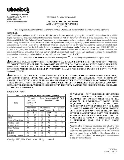
SPECIFICATIONS:<br />
Table 1: dBA Ratings for AMT Multitone Appliance<br />
Typical<br />
Anechoic<br />
Rated Reverberant dBA At 10<br />
Feet Per UL 464<br />
Tone dBA at 10<br />
Feet<br />
At Nominal At Minimum At Nominal<br />
Input Voltage Input Voltage Input Voltage<br />
HI STD HI STD HI STD<br />
Horn 99 93 88 79 88 82<br />
Bell 93 88 82 75 85 79<br />
March Time Horn 98 92 85 79 88 82<br />
Code 3 Horn 99 93 85 75 85 79<br />
Code 3 Tone 95 89 85 79 88 82<br />
Slow Whoop 99 94 82 75 85 79<br />
Siren 97 92 82 75 82 75<br />
HI/LO 93 85 82 75 85 79<br />
Vibrating Chimes 89 83 79 73* 82 75<br />
Copyright 1995, 1996 <strong>Wheelock</strong> Inc. All rights reserved.<br />
WARNING: AMT MULTITONE APPLIANCES<br />
SET ON “VIBRATING CHIME TONE” WITH<br />
STANDARD dBA DO NOT MEET THE 75 dBA<br />
MINIMUM UL REVERBERANT SOUND LEVEL<br />
REQUIRED FOR PUBLIC MODE FIRE<br />
PROTECTION SERVICE (NOTED BY * IN TABLE<br />
1). MODELS WITH SETTINGS WHICH PRODUCE<br />
LESS THAN 75 dBA MAY NOT BE HEARD. THIS<br />
SETTING IS ACCEPTABLE ONLY FOR GENERAL<br />
SIGNALING (NON-FIRE ALARM) USE. USE THE<br />
“HIGH” dBA SETTING WITH THIS TONE OR USE<br />
A DIFFERENT TONE FOR PUBLIC MODE<br />
SERVICE.<br />
Anechoic dBA is measured on axis in a non-reflective (free<br />
field) test room using fast meter response. For peak dBA<br />
(measured with peak meter response), add 5 dBA to typical<br />
anechoic values shown in Table 1. Reverberant dBA is a<br />
minimum UL rating based on sound power measurements<br />
in a reverberant test room.<br />
<strong>P82623</strong> A<br />
Sheet 1 of 7
Table 2: Current Ratings for AMT Multitone Audible Appliances<br />
Tone<br />
Tone<br />
Rated Average Current<br />
(AMPS)<br />
Rated Average Current<br />
(AMPS)<br />
Description 24VDC 12VDC<br />
HI dBA STD dBA HI dBA STD dBA<br />
Horn Broadband Horn (Continuous) 0.040 0.023 0.100 0.020<br />
Bell 1560 Hz Modulated (0.07 Sec. ON/Repeat) 0.016 0.012 0.031 0.010<br />
March Time Horn Horn (0.25 Sec. ON/0.25 Sec. OFF/Repeat) 0.040 0.023 0.100 0.020<br />
Code 3 Horn Horn (ANSI S3.41 Temporal Pattern) 0.040 0.023 0.100 0.020<br />
Code 3 Tone 500 Hz (ANSI S3.41 Temporal Pattern) 0.028 0.017 0.060 0.015<br />
Slow Whoop 500-1200Hz Sweep (4.0 Sec. ON/0.5 Sec. OFF/Repeat) 0.048 0.026 0.100 0.025<br />
Siren 600-1200Hz Sweep (1.0 Sec. ON/Repeat) 0.036 0.023 0.082 0.020<br />
HI/LO 1000/800 Hz (0.25 Sec. ON/Alternate) 0.020 0.015 0.044 0.013<br />
Vibrating Chime 700Hz (1.0 Sec. Decay/Repeat) 0.017 0.012 0.027 0.010<br />
Add 25% more input when operating the unit at maximum input voltage (15.6VDC for 12VDC models, 31VDC for 24VDC models).<br />
Rated Input Voltage: AMT Multitone Appliances set for 24VDC operation are UL Listed to operate over a voltage range from<br />
18VDC to 31VDC and AMT Multitone Appliances set for 12VDC operation are UL Listed to operate over a voltage range of<br />
10.5VDC to 15.6VDC using filtered DC or unfiltered FWR input voltage.<br />
WARNING: MAKE SURE THAT THE TOTAL AVERAGE CURRENT, TOTAL PEAK CURRENT AND TOTAL<br />
INRUSH CURRENT REQUIRED BY ALL APPLIANCES THAT ARE CONNECTED TO THE SYSTEM’S PRIMARY<br />
AND SECONDARY POWER SOURCES AND SIGNALING CIRCUITS DO NOT EXCEED THE POWER SOURCES’<br />
RATED CAPACITY OR THE CURRENT RATINGS OF ANY FUSES ON THE CIRCUITS TO WHICH THESE<br />
APPLIANCES ARE WIRED. OVERLOADING POWER SOURCES OR EXCEEDING FUSE RATINGS COULD RESULT<br />
IN LOSS OF POWER AND FAILURE TO ALERT OCCUPANTS DURING AN EMERGENCY, WHICH COULD RESULT<br />
IN PROPERTY DAMAGE AND SERIOUS INJURY OR DEATH TO YOU AND/OR OTHERS.<br />
When calculating the total average, peak and inrush currents: Use Table 2 to determine the highest value of “Rated Average Current”<br />
for an individual strobe (across the expected operating voltage range of the strobe), and the highest value of “Rated Inrush Current” or<br />
“Rated Peak Current” (whichever is higher) of an individual strobe (across the expected voltage range of the strobe), then multiply<br />
these values by the total number of strobes; be sure to add the currents for any other appliances, including audible signaling<br />
appliances, powered by the same source and include any required safety factors.<br />
If the inrush current or peak current exceeds the power supplies’ inrush capacity, the output voltage provided by the power supplies<br />
may drop below the listed voltage range of the appliances connected to the supply and the voltage may not recover in some types of<br />
power supplies. For example, an auxiliary power supply that lacks filtering at its output stage (either via lack of capacitance and/or<br />
lack of battery backup across the output) may exhibit this characteristic.<br />
CAUTION: Strobes are not designed to be used on coded systems in which the applied voltage is cycled on and off.<br />
The AMT Multitone audible appliances produce a brief inrush current that lasts for just 2 microseconds but can reach a peak value of<br />
8.0 Amps (11.2 amps for FWR input).<br />
<strong>P82623</strong> A<br />
Sheet 2 of 7
AMT MULTITONE SETTINGS:<br />
The Jumper Plug (DP1) and Switch (SW1) of the AMT Multitone Appliances, shown in Figure 1, are used to set the input voltage<br />
dBA sound output level and alarm tone. The factory settings are shown below. Read these instructions carefully before changing<br />
any of these factory settings.<br />
Figure 1.<br />
PC Board Layout Showing Location<br />
of Jumper Plug (DP1) and Switch (SW1)<br />
The Factory Settings are:<br />
24<br />
12<br />
24<br />
12<br />
24VDC: DP1 SET ON 24<br />
HIGH dBA: SW1 POS 1 = 1<br />
iority 1 (PRI 1)<br />
ority 2 (PRI 2)<br />
ority 3 (PRI 3)<br />
HORN TONE:<br />
BELL TONE: SW1 POS 2, 3, 4 = 1, 1<br />
SIREN TONE: }<br />
+PRI 1- +PRI 2- +PRI 3-<br />
STEP 1:<br />
Set desired input voltage and dBA sound output level as follows (Refer to Figures 2 and 3):<br />
AMT Multitone Appliances are field set for input voltage and dBA sound output level by inserting a Jumper Plug (DP1) and adjusting<br />
a four position Switch (SW1) as shown in Table 3 and Figures 2 and 3. Use DP1 to select the desired voltage and SW1 Position 1 to<br />
select the dBA sound output level.<br />
Table 3: Input Voltage and dBA Sound Output Level Settings<br />
Input Voltage and Decibel Level DP1 and SW1 Settings<br />
24 VDC/HIGH dBA: Set DP1 on 24; set SW1 POS 1 on 1 (Factory Setting)<br />
24 VDC/STD dBA: Set DP1 on 24; set SW1 POS 1 on 0<br />
12 VDC/HIGH dBA: Set DP1 on 12; set SW1 POS 1 on 1<br />
12 VDC/STD dBA: Set DP1 on 24; set SW1 POS 1 on 1<br />
Figure 2. Figure 3.<br />
Jumper Plug (DP1) Settings<br />
Switch (SW1) Settings<br />
(Use Needle Nose Pliers to Lift and Properly Insert the Jumper Plug)<br />
WARNING: DO NOT APPLY 24VDC INPUT IF THE JUMPER PLUG (DP1) IS SET ON 12. THIS CAN DAMAGE<br />
THE UNIT. DOUBLE CHECK THE JUMPER PLUG (DP1) AND SWITCH (SW1) SETTINGS TO MAKE SURE THEY<br />
ARE CORRECT. IMPROPER SETTINGS CAN DAMAGE THE UNIT OR RESULT IN NO SOUND OUTPUT OR A dBA<br />
SOUND OUTPUT LEVEL THAT IS BELOW THE 75dBA MINIMUM CODE REQUIREMENTS FOR PUBLIC MODE<br />
FIRE PROTECTION, WHICH COULD RESULT IN PROPERTY DAMAGE AND SERIOUS INJURY OR DEATH TO<br />
YOU AND/OR OTHERS.<br />
<strong>P82623</strong> A<br />
Sheet 3 of 7
STEP 2:<br />
Set desired alarm tone as follows (refer to Figure 3 and Table 4).<br />
AMT Multitone Appliances are field set for any one of eight groups of self-prioritized tones by setting a four-position switch (SW1)<br />
as shown in Figure 3 and Table 4. Use SW1 POS 2, 3, 4 to select the desired alarm tone (refer to Table 4 below).<br />
Table 4.<br />
Tones<br />
Switch Settings<br />
PRI 1 PRI 2 PRI 3 POS 2 POS 3 POS 4<br />
Horn Bell Siren 1 1 1<br />
Code 3 Horn Siren Vibrating Chime 1 0 1<br />
Slow Whoop March Time Horn HI/LO 0 0 1<br />
March Time Horn HI/LO Vibrating Chimes 1 1 0<br />
Code 3 Horn Bell Siren 0 1 1<br />
Siren Horn Vibrating Chime 0 1 0<br />
Bell March Time Horn Siren 1 0 0<br />
Code 3 Tone HI/LO Siren 0 0 0<br />
Note: The prioritized tones contained in each group is factory pre-set which can not be changed.<br />
Note: The Code 3 Horn and Code 3 Tone (set on HIGH dBA) incorporate the temporal pattern specified by ANSI/NFPA for standard<br />
emergency evacuation signaling. They should be used only for fire evacuation signaling and not for any other purpose.<br />
The Horn and Bell Tones can be used on coded systems with a minimum On-Time of 1/4 second if the audible and strobe are wired to<br />
operate independently. All other tones are recommended for use only on continuous (non-coded) systems.<br />
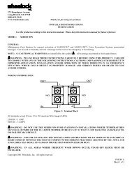
WIRING DIAGRAMS:<br />
Supervised System<br />
- Isolated inputs are provided for independent supervision and actuation of the three audible inputs.<br />
Unsupervised System<br />
Common Positive<br />
Unsupervised System<br />
Common Negative<br />
- For applications not requiring supervision: connect all positive<br />
(+) terminals to the power source. The negative (-) terminal for<br />
each appliance will actuate the appliance.<br />
- For applications not requiring supervision: connect all<br />
negative (-) terminals to the power source. The positive (+)<br />
terminal for each appliance will actuate the appliance.<br />
In case of simultaneous inputs, the three audible outputs are self-prioritized as follows: 1st priortiy= PRI 1; 2nd priority = PRI 2; 3rd<br />
priority = PRI 3. Leave any unused inputs disconnected.<br />
<strong>P82623</strong> A<br />
Sheet 4 of 7
1. AMT Multitone appliance models have in-out wiring<br />
terminals that accept two #12 to #18 American Wire Gauge<br />
(AWG) wires at each screw terminal. Strip leads 3/8 inches<br />
and connect to screw terminals.<br />
2. Break all in-out wire runs on supervised circuits to assure<br />
integrity of circuit supervision as shown on left. The<br />
polarity shown in the wiring diagrams is for operation of<br />
the appliances. The polarity is reversed by the FACP<br />
during supervision.<br />
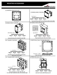
MOUNTING OPTIONS:<br />
CAUTION: The following figures show the maximum number of field wires (conductors) that can enter the backbox used with<br />
each mounting option. If these limits are exceeded, there may be insufficient space in the backbox to accommodate the field wires<br />
and stresses from the wires could damage the product.<br />
Although the limits shown for each mounting option comply with the National Electrical Code (NEC), <strong>Wheelock</strong> recommends use of<br />
the largest backbox option shown and the use of approved stranded field wires, whenever possible, to provide additional wiring room<br />
for easy installation and minimum stress on the product from wiring.<br />
10 8 8 4 10 8 8 4 12 12 12 12 12 12 12 12<br />
12 12 12 12 12 12 10 8 10 8 8 4<br />
<strong>P82623</strong> A<br />
Sheet 5 of 7
MOUNTING PROCEDURES:<br />
CAUTION: If sheated multiconductor cable or 3/4" conduit fittings are used, check that installed product has sufficient clearance<br />
and wiring room prior to installing backboxes and conduit.<br />
1. AMT Multitone Appliances can be flush mounted to a standard 4 inch square by 2-1/8 inch deep electrical box (Figure A) or a<br />
standard 2-gang by 2-1/2 inch minimum deep electrical box (Figure B).<br />
2. Select largest backbox shown in Mounting Options where possible, to provide additional wiring room for easy installation.<br />
3. Conduit entrance to backboxes should be selected to insure sufficient wiring clearance for installed equipment. When extension<br />
rings are required, conduit should enter through backbox, not extension ring. Use Steel City #53151/1-1/2" deep or #53171/2-1/8"<br />
deep extension rings or equal with same area cut out in back.<br />
4. The AMT-12/24 model can also be surface mounted to <strong>Wheelock</strong>'s Indoor/Outdoor Backbox (Model IOB) for indoor/outdoor use<br />
(Figure C).<br />
5. The AMT-12/24 model is supplied with four snap-in covers to hide the mounting holes and provide an attractive installation. The<br />
snap-in covers are interchangeable and have slots on each end so they can be removed if necessary (by prying them up with a thin<br />
blade screwdriver). To insert snap-in cover, slide one side partially into mounting hole recess; align the cover so that snap-in<br />
cover and grille are parallel to each other (not tilted) and snap cover into place.<br />
6. The IOB surface backbox has 1/2 inch conduit knockouts on two sides. It has a variety of knockouts on the back for mounting it<br />
to recessed electrical boxes and for wire entrances (Figure D). It can also be mounted to a surface with the two mounting ears that<br />
are supplied. The ears slide into slots on the back of the box. Use appropriate anchors for the wood screws that are supplied with<br />
the box (if necessary).<br />
7. For outdoor use, the IOB includes a prefastened gasket and four hole plugs. Make sure the condensation drain holes on the box<br />
face down and that the box is vertical to permit drainage of any moisture. Use the mounting ears to secure the box (do not use the<br />
back knockouts). Use the hole plugs to seal the unused mounting holes on the AMT Multitone grille (press them in securely from<br />
the back side of the grille). Mount the unit to the IOB with the four #8-18 screws supplied with the box.<br />
8. All models are UL Listed for indoor and outdoor use with a temperature range of -31 o F to +150 o F (-35 o C to +66 o C) and<br />
maximum humidity of 95% RH.<br />
WARNING: A SMALL POSSIBILITY EXISTS THAT THE USE OF MULTIPLE STROBES WITHIN A PERSON'S FIELD OF<br />
VIEW, UNDER CERTAIN CIRCUMSTANCES, MIGHT INDUCE A PHOTO-SENSITIVE RESPONSE IN PERSONS WITH EPILEPSY.<br />
STROBE REFLECTIONS IN A GLASS OR MIRRORED SURFACE MIGHT ALSO INDUCE SUCH A RESPONSE. TO MINIMIZE<br />
THIS POSSIBLE HAZARD, WHEELOCK STRONGLY RECOMMENDS THAT THE STROBES INSTALLED SHOULD NOT<br />
PRESENT A COMPOSITE FLASH RATE IN THE FIELD OF VIEW WHICH EXCEEDS FIVE (5) Hz AT THE OPERATING<br />
VOLTAGE OF THE STROBES. WHEELOCK ALSO STRONGLY RECOMMENDS THAT THE INTENSITY AND COMPOSITE<br />
FLASH RATE OF INSTALLED STROBES COMPLY WITH LEVELS ESTABLISHED BY APPLICABLE LAWS, STANDARDS,<br />
REGULATIONS, CODES AND GUIDELINES.<br />
NOTE: NFPA 72/ANSI 117.1 conform to ADAAG Equivalent Facilitation Guidelines in using fewer, higher intensity strobes within the<br />
same protected area.<br />
WARNING: IF AMT MULTITONE APPLIANCES ARE OPERATED WITHIN 15 INCHES OF A PERSON'S EAR, THEY CAN<br />
PRODUCE A SOUND PRESSURE LEVEL THAT EXCEEDS THE MAXIMUM 120 dBA PERMITTED BY ADA AND OSHA RULES.<br />
EXPOSURE TO SUCH SOUND LEVELS CAN RESULT IN DAMAGE TO A PERSON'S HEARING.<br />
WARNING: NFPA CODES REQUIRE SIGNALING APPLIANCES TO BE SUPERVISED. CHECK TO BE CERTAIN THAT<br />
UNSUPERVISED SIGNALING APPLIANCES DO NOT VIOLATE ANY APPLICABLE CODES.<br />
The AMT Multitone products and these instructions are copyrighted by <strong>Wheelock</strong> and contain proprietary, confidential and trade<br />
secrets of <strong>Wheelock</strong>. No part of the AMT Multitone products and these instructions may be photocopied, printed or reproduced in<br />
any form or modified, adapted, changed or enhanced, or converted to another programming language, or used to create updated,<br />
related or derivative works, without the prior written consent of <strong>Wheelock</strong>. No part of the AMT Multitone shall be decompiled,<br />
disassembled or reverse engineered.<br />
CAUTION: Check the installation instructions of the manufacturers of other equipment used in the system for any guidelines or<br />
restrictions on wiring and/or locating Notification Appliance Circuits (NAC) and notification appliances. Some system communication<br />
circuits and/or audio circuits, for example, may require special precautions to assure electrical noise immunity (e.g. audio crosstalk).<br />
ANY MATERIAL EXTRAPOLATED FROM THIS DOCUMENT OR FROM WHEELOCK MANUALS OR OTHER DOCUMENTS<br />
DESCRIBING THE PRODUCT FOR USE IN PROMOTIONAL OR ADVERTISING CLAIMS, OR FOR ANY OTHER USE,<br />
INCLUDING DESCRIPTION OF THE PRODUCT'S APPLICATION, OPERATION, INSTALLATION AND TESTING IS USED AT<br />
THE SOLE RISK OF THE USER AND WHEELOCK WILL NOT HAVE ANY LIABILITY FOR SUCH USE.<br />
IMPORTANT: READ SEPARATE "GENERAL INFORMATION" SHEET FOR INFORMATION ON THE PLACEMENT,<br />
LIMITATIONS, INSTALLATION, FINAL CHECKOUT AND PERIODIC TESTING OF NOTIFICATION APPLIANCES.<br />
<strong>P82623</strong> A<br />
Sheet 6 of 7
NOTE: This equipment has been tested and found to comply with the limits for a Class B digital device, pursuant to Part 15 of the<br />
FCC Rules. These limits are designed to provide reasonable protection against harmful interference in residential installation. This<br />
equipment generates, uses and can radiate radio frequency energy and, if not installed and used in accordance with the instructions,<br />
may cause harmful interference to radio communications. However, there is no guarantee that interference will not occur in a<br />
particular installation. If this equipment does cause harmful interference to radio or television reception, which can be determined by<br />
turning the equipment off and on, the user is encouraged to try to correct the interference by one or more of the following measures:<br />
1) Reorient or relocate the receiving antenna, 2) Increase the separation between the equipment and receiver, 3) Connect the<br />
equipment into an outlet on a circuit different from that to which the receiver is connected, and 4) Consult the dealer or an<br />
experienced radio/TV technician for help.<br />
Limited Warranty<br />
<strong>Wheelock</strong> products must be used within their published specifications and must be PROPERLY specified, applied, installed, operated,<br />
maintained and operationally tested in accordance with these instructions at the time of installation and at least twice a year or more<br />
often and in accordance with local, state and federal codes, regulations and laws. Specification, application, installation, operation,<br />
maintenance and testing must be performed by qualified personnel for proper operation in accordance with all of the latest National<br />
Fire Protection Association (NFPA), Underwriters' Laboratories (UL), Underwriters’ Laboratories of Canada (ULC), National<br />
Electrical Code (NEC), Occupational Safety and Health Administration (OSHA), local, state, county, province, district, federal and<br />
other applicable building and fire standards, guidelines, regulations, laws and codes including, but not limited to, all appendices and<br />
amendments and the requirements of the local authority having jurisdiction (AHJ). <strong>Wheelock</strong> products when properly specified,<br />
applied, installed, operated, maintained and operationally tested as provided above are warranted against mechanical and electrical<br />
defects for a period of three years from date of manufacture (as determined by date code). Correction of defects by repair or<br />
replacement shall be at <strong>Wheelock</strong>'s sole discretion and shall constitute fulfillment of all obligations under this warranty. THE<br />
FOREGOING LIMITED WARRANTY SHALL IMMEDIATELY TERMINATE IN THE EVENT ANY PART NOT FURNISHED BY<br />
WHEELOCK IS INSTALLED IN THE PRODUCT. THE FOREGOING LIMITED WARRANTY SPECIFICALLY EXCLUDES ANY<br />
SOFTWARE REQUIRED FOR THE OPERATION OF OR INCLUDED IN A PRODUCT. WHEELOCK MAKES NO<br />
REPRESENTATION OR WARRANTY OF ANY OTHER KIND, EXPRESS, IMPLIED OR STATUTORY WHETHER AS TO<br />
MERCHANTABILITY, FITNESS FOR A PARTICULAR PURPOSE OR ANY OTHER MATTER.<br />
USERS ARE SOLELY RESPONSIBLE FOR DETERMINING WHETHER A PRODUCT IS SUITABLE FOR THE USER'S PURPOSES,<br />
OR WHETHER IT WILL ACHIEVE THE USER'S INTENDED RESULTS. THERE IS NO WARRANTY AGAINST DAMAGE<br />
RESULTING FROM MISAPPLICATION, IMPROPER SPECIFICATION, ABUSE, ACCIDENT OR OTHER OPERATING<br />
CONDITIONS BEYOND WHEELOCK'S CONTROL.<br />
SOME WHEELOCK PRODUCTS CONTAIN SOFTWARE. WITH RESPECT TO THOSE PRODUCTS, WHEELOCK DOES NOT<br />
WARRANTY THAT THE OPERATION OF THE SOFTWARE WILL BE UNINTERRUPTED OR ERROR-FREE OR THAT THE<br />
SOFTWARE WILL MEET ANY OTHER STANDARD OF PERFORMANCE, OR THAT THE FUNCTIONS OR PERFORMANCE OF<br />
THE SOFTWARE WILL MEET THE USER'S REQUIREMENTS. WHEELOCK SHALL NOT BE LIABLE FOR ANY DELAYS,<br />
BREAKDOWNS, INTERRUPTIONS, LOSS, DESTRUCTION, ALTERATION, OR OTHER PROBLEMS IN THE USE OF A PRODUCT<br />
ARISING OUT OF OR CAUSED BY THE SOFTWARE.<br />
THE LIABILITY OF WHEELOCK ARISING OUT OF THE SUPPLYING OF A PRODUCT, OR ITS USE, WHETHER ON<br />
WARRANTIES, NEGLIGENCE, OR OTHERWISE, SHALL NOT IN ANY CASE EXCEED THE COST OF CORRECTING DEFECTS<br />
AS STATED IN THE LIMITED WARRANTY AND UPON EXPIRATION OF THE WARRANTY PERIOD ALL SUCH LIABILITY<br />
SHALL TERMINATE. WHEELOCK IS NOT LIABLE FOR LABOR COSTS INCURRED IN REMOVAL, REINSTALLATION OR<br />
REPAIR OF THE PRODUCT BY ANYONE OTHER THAN WHEELOCK OR FOR DAMAGE OF ANY TYPE WHATSOEVER,<br />
INCLUDING BUT NOT LIMITED TO, LOSS OF PROFIT OR INCIDENTAL OR CONSEQUENTIAL DAMAGES. THE FOREGOING<br />
SHALL CONSTITUTE THE SOLE REMEDY OF THE PURCHASER AND THE EXCLUSIVE LIABILITY OF WHEELOCK.<br />
IN NO CASE WILL WHEELOCK'S LIABILITY EXCEED THE PURCHASE PRICE PAID FOR A PRODUCT.<br />
Limitation of Liability<br />
WHEELOCK'S LIABILITY ON ANY CLAIM OF ANY KIND, INCLUDING NEGLIGENCE AND BREACH OF WARRANTY, FOR<br />
ANY LOSS OR DAMAGE RESULTING FROM, ARISING OUT OF, OR CONNECTED WITH THIS CONTRACT, OR FROM THE<br />
MANUFACTURE, SALE, DELIVERY, RESALE, REPAIR OR USE OF ANY PRODUCT COVERED BY THIS ORDER SHALL BE<br />
LIMITED TO THE PRICE APPLICABLE TO THE PRODUCT OR PART THEREOF WHICH GIVES RISE TO THE CLAIM.<br />
WHEELOCK'S LIABILITY ON ANY CLAIM OF ANY KIND SHALL CEASE IMMEDIATELY UPON THE INSTALLATION IN THE<br />
PRODUCT OF ANY PART NOT FURNISHED BY WHEELOCK. IN NO EVENT SHALL WHEELOCK BE LIABLE FOR ANY<br />
CLAIM OF ANY KIND UNLESS IT IS PROVEN THAT OUR PRODUCT WAS A DIRECT CAUSE OF SUCH CLAIM. FURTHER, IN<br />
NO EVENT, INCLUDING IN THE CASE OF A CLAIM OF NEGLIGENCE, SHALL WHEELOCK BE LIABLE FOR INCIDENTAL OR<br />
CONSEQUENTIAL DAMAGES. SOME STATES DO NOT ALLOW THE EXCLUSION OR LIMITATION OF INCIDENTAL OR<br />
CONSEQUENTIAL DAMAGES, SO THE PRECEDING LIMITATION MAY NOT APPLY TO ALL PURCHASERS.<br />
3/96<br />
<strong>P82623</strong> A<br />
Sheet 7 of 7