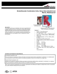
Series HS Horn and Horn Strobe Appliances - Cooper Industries
Series HS Horn and Horn Strobe Appliances - Cooper Industries
Series HS Horn and Horn Strobe Appliances - Cooper Industries

Create successful ePaper yourself
Turn your PDF publications into a flip-book with our unique Google optimized e-Paper software.
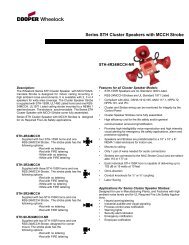
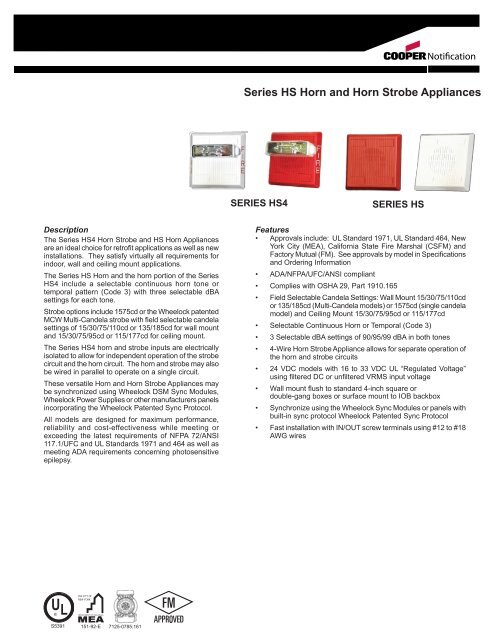
Notification<strong>Series</strong> <strong>HS</strong> <strong>Horn</strong> <strong>and</strong> <strong>Horn</strong> <strong>Strobe</strong> <strong>Appliances</strong>SERIES <strong>HS</strong>4SERIES <strong>HS</strong>DescriptionThe <strong>Series</strong> <strong>HS</strong>4 <strong>Horn</strong> <strong>Strobe</strong> <strong>and</strong> <strong>HS</strong> <strong>Horn</strong> <strong>Appliances</strong>are an ideal choice for retrofit applications as well as newinstallations. They satisfy virtually all requirements forindoor, wall <strong>and</strong> ceiling mount applications.The <strong>Series</strong> <strong>HS</strong> <strong>Horn</strong> <strong>and</strong> the horn portion of the <strong>Series</strong><strong>HS</strong>4 include a selectable continuous horn tone ortemporal pattern (Code 3) with three selectable dBAsettings for each tone.<strong>Strobe</strong> options include 1575cd or the Wheelock patentedMCW Multi-C<strong>and</strong>ela strobe with field selectable c<strong>and</strong>elasettings of 15/30/75/110cd or 135/185cd for wall mount<strong>and</strong> 15/30/75/95cd or 115/177cd for ceiling mount.The <strong>Series</strong> <strong>HS</strong>4 horn <strong>and</strong> strobe inputs are electricallyisolated to allow for independent operation of the strobecircuit <strong>and</strong> the horn circuit. The horn <strong>and</strong> strobe may alsobe wired in parallel to operate on a single circuit.These versatile <strong>Horn</strong> <strong>and</strong> <strong>Horn</strong> <strong>Strobe</strong> <strong>Appliances</strong> maybe synchronized using Wheelock DSM Sync Modules,Wheelock Power Supplies or other manufacturers panelsincorporating the Wheelock Patented Sync Protocol.All models are designed for maximum performance,reliability <strong>and</strong> cost-effectiveness while meeting orexceeding the latest requirements of NFPA 72/ANSI117.1/UFC <strong>and</strong> UL St<strong>and</strong>ards 1971 <strong>and</strong> 464 as well asmeeting ADA requirements concerning photosensitiveepilepsy.Features• Approvals include: UL St<strong>and</strong>ard 1971, UL St<strong>and</strong>ard 464, NewYork City (MEA), California State Fire Marshal (CSFM) <strong>and</strong>Factory Mutual (FM). See approvals by model in Specifications<strong>and</strong> Ordering Information• ADA/NFPA/UFC/ANSI compliant• Complies with OSHA 29, Part 1910.165• Field Selectable C<strong>and</strong>ela Settings: Wall Mount 15/30/75/110cdor 135/185cd (Multi-C<strong>and</strong>ela models) or 1575cd (single c<strong>and</strong>elamodel) <strong>and</strong> Ceiling Mount 15/30/75/95cd or 115/177cd• Selectable Continuous <strong>Horn</strong> or Temporal (Code 3)• 3 Selectable dBA settings of 90/95/99 dBA in both tones• 4-Wire <strong>Horn</strong> <strong>Strobe</strong> Appliance allows for separate operation ofthe horn <strong>and</strong> strobe circuits• 24 VDC models with 16 to 33 VDC UL “Regulated Voltage”using filtered DC or unfiltered VRMS input voltage• Wall mount flush to st<strong>and</strong>ard 4-inch square ordouble-gang boxes or surface mount to IOB backbox• Synchronize using the Wheelock Sync Modules or panels withbuilt-in sync protocol Wheelock Patented Sync Protocol• Fast installation with IN/OUT screw terminals using #12 to #18AWG wiresU LTHE CITY OFNEW YORKDEPARTMENT OF BUILDINGS®S5391 151-92-E 7125-0785:161
NOTE: All CAUTIONS <strong>and</strong> WARNINGS are identified by the symbol. All warnings are printed in bold capital letters.WARNING: PLEASE READ THESE SPECIFICATIONS AND ASSOCIATED INSTALLATION INSTRUCTIONS CAREFULLY BEFORE USING, SPECIFYING ORAPPLYING THIS PRODUCT. VISIT WWW.COOPERNOTIFICATION.COM OR CONTACT COOPER WHEELOCK FOR THE CURRENT INSTALLATION INSTRUCTIONS.FAILURE TO COMPLY WITH ANY OF THESE INSTRUCTIONS, CAUTIONS OR WARNINGS COULD RESULT IN IMPROPER APPLICATION, INSTALLATION AND/OROPERATION OF THESE PRODUCTS IN AN EMERGENCY SITUATION, WHICH COULD RESULT IN PROPERTY DAMAGE, AND SERIOUS INJURY OR DEATH TO YOUAND/OR OTHERS.General Notes:• <strong>Strobe</strong>s are designed to flash at 1 flash per second minimum over their “Regulated Voltage Range”. Note that NFPA-72 specifies a flash rate of 1to 2 flashes per second <strong>and</strong> ADA Guidelines specify a flash rate of 1 to 3 flashes per second.• All c<strong>and</strong>ela ratings represent minimum effective <strong>Strobe</strong> intensity based on UL St<strong>and</strong>ard 1971.• “Regulated Voltage Range” is the newest terminology used by UL to identify the voltage range. Prior to this change UL used theterminology “Listed Voltage Range”.Table 1: Ratings Per UL St<strong>and</strong>ard 1971ModelNumberInputVoltageVDCRegulatedVoltage RangeVDC/FWR<strong>Strobe</strong>C<strong>and</strong>ela (CD)<strong>HS</strong>4-24MCW 24 16.0 - 33.0 15/30/75/110<strong>HS</strong>4-241575W 24 16.0 - 33.0 15 (75 on Axis)<strong>HS</strong>4-24MCWH 24 16.0 - 33.0 135/185<strong>HS</strong>-24 24 16.0 - 33.0 -<strong>HS</strong>4-24MCC 24 16.0-33.0 15/30/75/95<strong>HS</strong>4-24MCCH 24 16.0-33.0 115/177Table 2: dBA Ratings for <strong>Horn</strong>DescriptionVolumeReverberant dBA@ 10ft per UL 46424VDCAnechoic dBA@ 10 ft24VDC<strong>HS</strong>/<strong>HS</strong>4<strong>Series</strong>Audible Current<strong>HS</strong> <strong>and</strong> <strong>HS</strong>4Continuous<strong>Horn</strong>Code 3<strong>Horn</strong>High 91 99Med 88 95Low 83 90High 87 99Med 84 95Low 79 90High (99) dBA Med (95) dBA Low (90) dBA24 vdc 0.098 0.052 0.024UL max* 0.110 0.068 0.027Table 3: Average RMS <strong>Strobe</strong> CurrentCeiling MountWall Mount24MCC24MCCH<strong>HS</strong>4-241575W <strong>HS</strong>4-24MCW <strong>HS</strong>4-24MCWH15cd 30cd 75cd 95cd 115cd 177cd0.065 0.105 0.189 0.249 0.300 0.4201575cd 15cd 30cd 75cd 110cd 135cd 185cd0.090 0.060 0.092 0.165 0.220 0.300 0.420* RMS current ratings are per UL average RMS method. UL max current rating is the maximum RMS current within the listed voltage range(16-33v for 24v units). For strobes the UL max current is usually at the minimum listed voltage (16v for 24v units). For audibles the maxcurrent is usually at the maximum listed voltage (33v for 24v units). For unfiltered FWR ratings, see installation instructions.
Wiring Diagrams #<strong>HS</strong>4 (4WIRE) APPLIANCE INDEPENDENT OPERATION OF AUDIBLESIGNAL AND STROBEFROM PRECEDINGAPPLIANCE,SYNC MODULE,POWER SUPPLY orFACP+-+-TO NEXTAPPLIANCEOR EOLR+ -- +FROM PRECEDINGAPPLIANCE,DSM,WHEELOCKPOWER SUPPLIESor FACP-+-+TO NEXTAPPLIANCEOR EOLR<strong>Horn</strong> <strong>and</strong> <strong>Strobe</strong> on separate circuits<strong>HS</strong>4 AND <strong>HS</strong> APPLIANCES SYNCHRONIZED WITH DSM MODULEDUAL CLASS “A” NAC CIRCUIT WITH NO AUDIBLE SILENCEFEATURE<strong>HS</strong>4 OR <strong>HS</strong> APPLIANCES SYNCHRONIZED WITH DSM MODULE2 CLASS “B” CIRCUITS<strong>Horn</strong> <strong>and</strong> <strong>Strobe</strong> wired in parallel<strong>Horn</strong> <strong>and</strong> <strong>Strobe</strong> on separate circuitsSpecifications <strong>and</strong> Ordering InformationModel NumberOrderCode<strong>Strobe</strong>C<strong>and</strong>elaNon-SyncSync w/ DSM orWheelock PowerSupplies24VDC2WIRE4WIREMountingOptions**Agency ApprovalsUL MEA FM CSFM<strong>HS</strong>4-24MCW-FR 3150 15/30/75/110 X X X X X D,E,F,L,M,O,P,R X X X X<strong>HS</strong>4-24MCW-FW 3151 15/30/75/110 X X X X X D,E,F,L,M,O,P,R X X X X<strong>HS</strong>4-241575W-FR 3176<strong>HS</strong>4-121575W-FR 317715 (75 onAxis)15 (75 onAxis)Note: <strong>HS</strong>4 or <strong>HS</strong> must be set on Code 3 horn tone to achievesynchronized temporal (Code 3) tone. Refer to installation instruction.X X X X X D,E,F,L,M,O,P,R X X X XX X X X X D,E,F,L,M,O,P,R X X X X<strong>HS</strong>4-24MCWH-FR 3132 135/185 X X X X X D,E,F,L,M,O,P,R X X - X<strong>HS</strong>4-24MCWH-FW 3148 135/185 X X X X X D,E,F,L,M,O,P,R X X - X<strong>HS</strong>-24-R 3152 - X X X X D,E,F,L,M,O,P,R X X X X<strong>HS</strong>-24-W 3153 - X X X X D,E,F,L,M,O,P,R X X X X<strong>HS</strong>4-24MCC-FR** 6264 - X X X X X D,E,F,L,M,O,P,R X X X X<strong>HS</strong>4-24MCC-FW** 6250 - X X X X X D,E,F,L,M,O,P,R X X X X<strong>HS</strong>4-24MCCH-FR** 6228 - X X X X X D,E,F,L,M,O,P,R X X X X<strong>HS</strong>4-24MCCH-FW** 6225 - X X X X X D,E,F,L,M,O,P,R X X X XModels are available in either Red or White. Call Customer Service for Order Code & Delivery.**Refer to Data Sheet S7000 for Mounting Options.NOTE: Due to continuous development of our products, specifications <strong>and</strong> offerings are subject to change without noticein accordance with Wheelock Inc. st<strong>and</strong>ard terms <strong>and</strong> conditions.
Architects <strong>and</strong> Engineers SpecificationsThe audible/visual notification appliance shall be Wheelock <strong>Series</strong> <strong>HS</strong>4 <strong>Horn</strong> <strong>Strobe</strong> <strong>and</strong> <strong>HS</strong> <strong>Horn</strong> <strong>Appliances</strong> or approved equals. The<strong>Series</strong> <strong>HS</strong>4 <strong>and</strong> <strong>HS</strong> appliance shall meet ad be listed for UL St<strong>and</strong>ard 1971 (Emergency Devices for the Hearing-Impaired for IndoorFire Protection Service) <strong>and</strong> St<strong>and</strong>ard 464 (Fire Protective Signaling). The horn strobe shall be listed for indoor use <strong>and</strong> shall meetthe requirement of FCC Part 15 Class B. All inputs shall be compatible with st<strong>and</strong>ard reverse polarity supervision of circuit wiring bythe Fire Alarm Control Panel (FACP).The <strong>HS</strong> <strong>Horn</strong> <strong>and</strong> the audible portion of the <strong>HS</strong>4 appliance shall have a minimum of three (3) field selectable setting for dBA levels <strong>and</strong>shall have a choice of continuous or temporal (Code 3) audible outputs.The strobe portion of the appliance shall produce a flash rate of one (1) flash per second over the Regulated Voltage Range <strong>and</strong> shallincorporate a Xenon flashtube enclosed in a rugged Lexan ® lens. The <strong>Series</strong> <strong>HS</strong>4 shall be of low current design. Where wall mount,Multi-C<strong>and</strong>ela appliances are specified, the strobe intensity shall have field selectable settings <strong>and</strong> shall be rated per UL St<strong>and</strong>ard 1971for: 15/30/75/110cd or 135/185cd. The selector switch for selecting the c<strong>and</strong>ela setting shall be tamper resistant. The 1575 c<strong>and</strong>elastrobe shall be specified when 15 c<strong>and</strong>ela UL St<strong>and</strong>ard 1971 Listing with 75 c<strong>and</strong>ela on-axis is required. Where ceiling mount, multic<strong>and</strong>elaappliances are specified, the strobe intensity shall have field selectable settings <strong>and</strong> shall be rated per UL st<strong>and</strong>ard 1971 for15/30/75/95cd or 115/177cd.When synchronization is required, the appliance shall be compatible with Wheelock DSM Sync Modules, Wheelock Power Supplies orother manufacturers panels incorporating the Wheelock Patented Sync Protocol. The strobes shall not drift out of synchronization atany time during operation. If the sync module or Power Supply fails to operate, (i.e., contacts remain closed), the strobes shall revertto a non-synchronized flash-rate.All notification appliances shall be backward compatible.WE ENCOURAGE AND SUPPORT NICET CERTIFICATION3 YEAR WARRANTYS2400 <strong>HS</strong> 06/11NJ Location273 Branchport Ave.Long Branch, NJ 07740P: 800-631-2148F: 732-222-8707www.coopernotification.com<strong>Cooper</strong> Notification isNotification