F&W Instructions - Vent-Axia
F&W Instructions - Vent-Axia
F&W Instructions - Vent-Axia

Create successful ePaper yourself
Turn your PDF publications into a flip-book with our unique Google optimized e-Paper software.
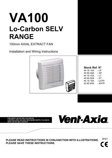
VA100<br />
Lo-Carbon SELV<br />
RANGE<br />
100mm AXIAL EXTRACT FAN<br />
Installation and Wiring <strong>Instructions</strong><br />
Stock Ref. N°<br />
44 16 14A - LP<br />
45 90 49A - XP<br />
44 16 15A - LT<br />
45 90 50A - XT<br />
44 16 16A - LHTP<br />
43 60 64A - XHTP<br />
FAN UNITS 12V DC SELV (CLASS III)<br />
CONTROLLERS 220-240V 50Hz MAINS SUPPLY (CLASS II)<br />
WITH 12V DC SELV OUTPUT<br />
PLEASE READ INSTRUCTIONS IN CONJUNCTION WITH ILLUSTRATIONS.<br />
PLEASE SAVE THESE INSTRUCTIONS.<br />
IPX7
Installation and Wiring <strong>Instructions</strong> for the VA100 Lo-Carbon SELV Range of<br />
Extractor Fans.<br />
IMPORTANT:<br />
READ THESE INSTRUCTIONS<br />
BEFORE COMMENCING THE<br />
INSTALLATION<br />
DO NOT install this product in areas where the following may be present or occur:<br />
• Excessive oil or a grease laden atmosphere.<br />
• Corrosive or flammable gases, liquids or vapours.<br />
• Ambient temperatures higher than 40°C or less than –5°C.<br />
• Possible obstructions which would hinder the access or removal of the Fan.<br />
SAFETY AND GUIDANCE NOTES<br />
A. All wiring to be in accordance with the current I.E.E. Regulations, or the<br />
appropriate standards of your country and MUST be installed by a suitably<br />
qualified person.<br />
B. The Fan should be provided with a local isolator switch capable of disconnecting<br />
all poles, having a contact separation of at least 3mm.<br />
C. Ensure that the mains supply (Voltage, Frequency, and Phase) complies with the<br />
rating label.<br />
D. The Fan should only be used in conjunction with the appropriate <strong>Vent</strong>-<strong>Axia</strong><br />
products.<br />
E. The fan should only be used in conjunction with fixed wiring.<br />
F. When the Fan is used to remove air from a room containing a fuel-burning<br />
appliance, ensure that the air replacement is adequate for both the fan and the<br />
fuel-burning appliance.<br />
G. The Fan should not be used where it is liable to be subject to direct water spray<br />
for prolonged periods of time.<br />
H. Where ducted Fans are used to handle moisture-laden air, a condensation trap<br />
should be fitted. Horizontal ducts should be arranged to slope slightly downwards<br />
away from the Fan.<br />
I. This appliance is not intended for use by persons (including children) with<br />
reduced physical, sensory or mental capabilities, or lack of experience and<br />
knowledge, unless they have been given supervision or instruction concerning<br />
use of the appliance by a person responsible for their safety.<br />
J. Children should be supervised to ensure that they do not play with the appliance.<br />
K. Stationary appliances not fitted with means for disconnection from the supply<br />
mains having a contact separation in all poles that provide full disconnection<br />
under over voltage category III, the instructions state that means for<br />
disconnection must be incorporated in the fixed wiring in accordance with the<br />
wiring rules.<br />
IMPORTANT:- ONLY CONNECT TOGETHER PRODUCTS FROM THE VA100 LO-<br />
CARBON SELV RANGE SINCE THE FANS ARE SPECIALLY DESIGNED TO WORK<br />
ON 12V DC AND ARE NOT COMPATIBLE WITH OTHER VENT-AXIA<br />
CONTROLLERS. DO NOT CONNECT MORE THAN ONE FAN TO THE<br />
CONTROLLER.
DESCRIPTION<br />
The VA100 Lo-Carbon SELV fan is an axial extraction fan suitable for domestic<br />
bathrooms and WC’s and is with shutter timer and humidity combinations. The fan<br />
can be wall, panel/ceiling or window mounted using the appropriate ducting/grille<br />
kit (see Accessories section below).<br />
Long life ball bearing DC motor with anti-vibration mounts provides low noise<br />
transmission into plasterboard/panels for quiet operation compared with other DC<br />
motor based fans.<br />
ACCESSORIES (not supplied) Please see www.vent-axia.com for more<br />
information.<br />
WALL FITTING KIT<br />
A range of 100mm wall kits are available for installing into most walls using<br />
telescopic liners supplied. White stock ref.: 254102, Brown stock ref: 254100.<br />
WINDOW FITTING KIT<br />
Two window kits are available, for existing 105-110mm diameter holes use stock<br />
ref. 254101A. For 110-140mm holes use stock ref. 443234.<br />
A. INSTALLATION<br />
SITING THE CONTROLLER<br />
1. The controller must not be installed in a shower cubicle or enclosure. It must<br />
be sited away from direct sources of water spray and out of reach (1.5m) of<br />
a person using a fixed bath or shower.<br />
2. Site away from direct sources of heat. Ambient temperature range 0 to<br />
40ºC. Do not site in an area containing excessive levels of grease.<br />
3. Decide where to site the controller and fan (see section siting the fan), and<br />
work out the required cable runs.<br />
PANEL/CEILING MOUNTING<br />
1. For panel/ceiling mounting the fan should be installed into a closed duct<br />
system of at least 1.2m long (max 3m) or protected by an exterior air grille<br />
that must comply with the standard requirements of your country to prevent<br />
access to the fans impeller.<br />
2. Cut a 105mm diameter hole.<br />
3. Loosen the screw at the bottom of the grille and remove the grille. Mark the<br />
screw centres through the holes in the fan back plate. Drill, plug and screw<br />
into position.<br />
4. Attach ducting as required for the installation.<br />
5. Wire the fan as described in Section B-Wiring. Adjust any settings as<br />
required (see Section C-Setup).<br />
6. Replace the grille and tighten the retaining screw.<br />
7. After installation, ensure impeller rotates freely and the shutters can open.
WALL MOUNTING (WALL KIT SUPPLIED SEPARATELY – SEE ACCESSORIES ON PREVIOUS PAGE)<br />
1. For wall mounting cut a 117mm diameter hole through the wall and insert<br />
the wall sleeve. Slope the sleeve slightly downwards away from the fan. Cut<br />
to length and cement both ends into position flush with the wall faces.<br />
2. Loosen the screw in the bottom of the grille and remove the front grille. Mark<br />
the screw centres through the holes in the fan back plate. Drill, plug and<br />
screw into position. Fix exterior grille into position with the louvres positioned<br />
downwards. (Note:- The grille must comply with the standard requirements<br />
of your country to prevent access to the fans impeller)<br />
3. Wire the fan as described in Section B-Wiring. Adjust any settings as<br />
required (see Section C-Setup).<br />
4. Replace the grille and tighten the retaining screw.<br />
5. After installation, ensure impeller rotates freely and the shutters can open.<br />
WINDOW MOUNTING (WINDOW KIT SUPPLIED SEPARATELY – SEE ACCESSORIES ABOVE)<br />
The following instructions are for 105-110mm holes only – using the<br />
254101A window mounting kit. For 110-140mm holes please use<br />
443234 window kit and refer to the supplied instructions.<br />
1. Cut a 105mm diameter hole in the glass.<br />
2. Fit spacers as required behind the fan back plate, engaging the locating pips<br />
in the corner holes.<br />
3. Place the fan spigot through the hole in the glass from the inside, with a<br />
gasket on each side of the glass.<br />
4. From the outside, place on the remaining spacer, with the locating pips<br />
facing outwards. For double-glazing and materials up to 40mm thick, one or<br />
more spacers may be discarded.<br />
5. Draw the assembly together with the threaded fixing ring. Do not overtighten.<br />
6. Fix the exterior grille in position, using the screws provided, with the louvres<br />
pointing downwards.<br />
AFTER INSTALLATION ENSURE IMPELLER ROTATES FREELY<br />
B. WIRING.<br />
WARNING: THE FAN AND ANCILLARY CONTROL EQUIPMENT MUST BE<br />
ISOLATED FROM THE POWER SUPPLY DURING THE INSTALLATION / OR<br />
MAINTENANCE.<br />
IMPORTANT: The Controller MUST be surface mounted to allow air to freely<br />
circulate around the unit. When installed in a loft void it MUST NOT be enclosed<br />
or covered with insulation.<br />
There are two methods of cable entry to the fan. If the side cable entry option is<br />
used, ensure the supplied grommet is used and maintains a good seal to prevent<br />
water ingress.<br />
The fan must be powered at all times to allow the shutter to work correctly. If there<br />
is a requirement to switch the fan via an external switch, this should be connected<br />
to the LS connection and not by switching L/N supply.
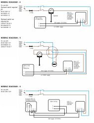
1. Select and follow the appropriate wiring diagram. (Fig. 2 or 3)<br />
2. Check all connections have been made correctly and ensure all terminal<br />
connections and cable clamps are securely fastened.<br />
3. Ensure the impeller rotates and is free from obstructions.<br />
4. DO NOT TEST THE FAN WITHOUT THE GRILLE SECURELY FASTENED.<br />
THIS COULD POTENTIALLY CAUSE DAMAGE TO THE SHUTTER<br />
MECHANISM.<br />
C. SETUP<br />
WARNING: THE FAN AND ANCILLARY CONTROL EQUIPMENT<br />
MUST BE ISOLATED FROM THE POWER SUPPLY DURING THE<br />
INSTALLATION / OR MAINTENANCE.<br />
SPEED SETTING (Fig. 4):<br />
The fan has two speed settings for different installation requirements:<br />
1) High speed – for ducted installations: Replace jumper.<br />
2) Normal speed – for wall/window installations: Remove jumper.<br />
TIMER ADJUSTMENT (LT/XT/LHTP/XHTP MODELS)<br />
BEFORE ADJUSTING THE TIMER, SWITCH OFF THE MAINS SUPPLY. TIMER<br />
SHOULD ONLY BE ADJUSTED BEFORE OR DURING INSTALLATION.<br />
1. Remove the fan grille. The controller is factory set at 15 minutes<br />
approx. The overrun time period can be adjusted from approximately<br />
3-30 minutes by altering the adjuster on the control PCB.<br />
2. To REDUCE the operating time, use a small screwdriver to turn the<br />
adjuster Fig.4. ANTI-CLOCKWISE.<br />
3. To INCREASE the operating time, use a small screwdriver to turn the<br />
adjuster Fig.4. CLOCKWISE.<br />
4. Replace the fan grille.<br />
HUMIDITY SET-POINT ADJUSTMENT (LHTP/XHTP MODELS ONLY)<br />
BEFORE ADJUSTING THE CONTROLLER, SWITCH OFF THE MAINS SUPPLY.<br />
HUMIDISTAT SHOULD ONLY BE ADJUSTED BEFORE OR DURING<br />
INSTALLATION.<br />
1. Remove the fan grille. The controller is factory set to switch on at<br />
about 70% RH. The humidity set point can be adjusted from 65-<br />
95%RH by altering the adjuster on the control PCB.<br />
2. To LOWER the set-point use a small screwdriver to turn the adjuster<br />
Fig.4. ANTI-CLOCKWISE. This makes the controller MORE sensitive.<br />
3. To RAISE the set-point use a small screwdriver to turn the adjuster<br />
Fig.4. CLOCKWISE. This makes the controller LESS sensitive.<br />
4. Replace the fan grille.
IMPORTANT: Upon installation it is possible that the humidity controller will make<br />
the fan run continuously until it has acclimatised to the environment. As part of the<br />
installation process it is important to set/adjust the humidity sensitivity to the<br />
desired position. The controller is already factory set to switch on at about 70%<br />
R.H. If the room has not had a fan correctly working for sometime, the fan may run<br />
continuously for 2 or more weeks until the humidity drops below 70%RH.<br />
PULLCORD OPERATION (LP/XP, LHTP/XHTP)<br />
The PULLCORD will activate the fan when switched. For the HTP models, the fan<br />
will return to the auto humidity sensing mode once the pullcord is switched into the<br />
off position. The LED indicator light will only activate if the PULLCORD is in the<br />
ON position.<br />
LED INDICATOR LIGHT OPERATION<br />
The Neon will activate whenever the LS or PULLCORD is activated. The LED<br />
indicator light will switch off if the fan is running in Timer overrun or Humidity mode<br />
(if applicable).<br />
D. SERVICING AND MAINTENANCE.<br />
WARNING: THE FAN AND ANCILLARY CONTROL EQUIPMENT<br />
MUST BE ISOLATED FROM THE POWER SUPPLY DURING<br />
MAINTENANCE.<br />
1. At intervals appropriate to the installation, the fan should be inspected and<br />
cleaned to ensure there is no build up of dirt or other deposits.<br />
2. Wipe the inlets and front face with a damp cloth until clean.<br />
The fan has sealed for life bearings, which do not require lubrication.
Fig.1.<br />
<br />
<br />
Fig.2 Models: LP/XP (LHTP/XHTP – if the Timer is not used)<br />
1 Phase Supply<br />
(220-240V 50Hz).<br />
L<br />
~<br />
N<br />
FUSE<br />
12V D.C<br />
SELV Supply<br />
L<br />
N<br />
LS<br />
1<br />
2<br />
3<br />
Fan<br />
Switched<br />
Fused Spur<br />
(3A)<br />
LS<br />
N<br />
L<br />
12V<br />
Controller<br />
LS<br />
0V<br />
Fig.3 Models: LT/XT, LHTP/XHTP<br />
~N<br />
12V D.C<br />
SELV Supply<br />
L<br />
1<br />
Fan<br />
N 2<br />
LS 3<br />
LS<br />
N<br />
L<br />
12V<br />
LS<br />
0V<br />
Controller
Fig.4.<br />
SPEED SETTING:<br />
The fan has two speed settings for different<br />
installation requirements:<br />
• High speed – for ducted installations:<br />
Replace jumper.<br />
• Normal speed – for wall/window<br />
installations: Remove jumper.<br />
- +<br />
- +<br />
Humidistat set point adjustment (65-95%RH)<br />
Overrun timer adjustment (1-30min)<br />
The<br />
Guarantee<br />
Applicable only to products installed and used in the United Kingdom. For details of guarantee outside the United Kingdom contact your local<br />
supplier.<br />
<strong>Vent</strong>-<strong>Axia</strong> guarantees its products for two years from date of purchase against faulty material or workmanship. In the event of any part being found<br />
to be defective, the product will be repaired, or at the Company’s option replaced, without charge, provided that the product:-<br />
• Has been installed and used in accordance with the instructions given with each unit.<br />
• Has not been connected to an unsuitable electricity supply. (The correct electricity supply voltage is shown on the product rating label<br />
attached to the unit).<br />
• Has not been subjected to misuse, neglect or damage.<br />
• Has not been modified or repaired by any person not authorised by the company.<br />
IF CLAIMING UNDER TERMS OF GUARANTEE<br />
Please return the complete product, carriage paid to your original supplier or nearest <strong>Vent</strong>-<strong>Axia</strong> Centre, by post or personal visit. Please ensure<br />
that it is adequately packed and accompanied by a letter clearly marked “Guarantee Claim” stating the nature of the fault and providing evidence of<br />
date and source of purchase.<br />
The guarantee is offered to you as an extra benefit, and does not effect your legal rights<br />
Head Office: Fleming Way, Crawley, West Sussex, RH10 9YX. Tel: 01293 526062 Fax: 01293 551188<br />
UK NATIONAL CALL CENTRE, Newton Road, Crawley, West Sussex, RH10 9JA<br />
SALES ENQUIRIES: Tel: 0844 8560590 Fax: 01293 565169<br />
TECHNICAL SUPPORT: Tel: 0844 8560594 Fax: 01293 532814<br />
For details of the warranty and returns procedure please refer to www.vent-axia.com or write to <strong>Vent</strong>-<strong>Axia</strong> Ltd, Fleming Way, Crawley, RH10 9YX<br />
444985B 0811