INFORMATION & REQUIREMENTS ELECTRIC SERVICE - NStar
INFORMATION & REQUIREMENTS ELECTRIC SERVICE - NStar
INFORMATION & REQUIREMENTS ELECTRIC SERVICE - NStar

You also want an ePaper? Increase the reach of your titles
YUMPU automatically turns print PDFs into web optimized ePapers that Google loves.
IMPORTANT <strong>INFORMATION</strong> FOR<br />
BUILDERS AND CONTRACTORS<br />
NEED POWER (New Construction Electric)<br />
Includes installing new electric services, upgrading or moving a<br />
service and temporary disconnection of a service<br />
Phone . . . . . . . . . . . . . . . . . . . . . . . . . . . .888-633-3797<br />
Fax: . . . . . . . . . . . . . . . . . . . . . . . . . . . . .781-441-8721<br />
DIG SAFE . . . . . . . . . . . . . . . . . . . . . . . .888-344-7233<br />
GENERAL CUSTOMER <strong>SERVICE</strong><br />
Residential Customers . . . . . . . . . . . . . . . . 800-592-2000<br />
Business Customers . . . . . . . . . . . . . . . . . .800-340-9822<br />
STREETLIGHT REPAIRS . . . . . . . . . . . . .800-785-4837<br />
ENERGY EFFICIENCY<br />
Residential . . . . . . . . . . . . . . . . . . . . . . . . .781-441-8720<br />
Business . . . . . . . . . . . . . . . . . . . . . . . . . .781-441-8592<br />
Cape Cod Only . . . . . . . . . . . . . . . . . . . . .800-797-6699<br />
(Cape Light Compact)<br />
CLAIMS - voice mail box . . . . . . . . . . . . .866-678-2792<br />
THEFT OF <strong>SERVICE</strong> . . . . . . . . . . . . . . . .781-441-8537<br />
www.nstar.com/business/builders_contractors<br />
<strong>INFORMATION</strong> & <strong>REQUIREMENTS</strong> FOR <strong>ELECTRIC</strong> <strong>SERVICE</strong><br />
<strong>INFORMATION</strong> &<br />
<strong>REQUIREMENTS</strong><br />
FOR<br />
<strong>ELECTRIC</strong> <strong>SERVICE</strong><br />
CUSTOMERS<br />
<strong>ELECTRIC</strong>IANS<br />
ARCHITECTS<br />
ENGINEERS<br />
BUILDERS<br />
INSPECTORS<br />
Revised 2009<br />
Revised 2009
INTRODUCTION<br />
At NSTAR Electric, we are committed to serving our customers<br />
well, and providing them with safe, reliable electric service is one<br />
of our most important priorities.This handbook, Information &<br />
Requirements for Electric Service, was designed with that priority<br />
in mind, and it contains the requirements within which safe<br />
electric service can be supplied to our customers.<br />
Inside you will find answers to many of the questions customers,<br />
electricians, architects, engineers, builders, and inspectors<br />
frequently ask related to electric service.You will also find there<br />
have been a number of policy changes and other updates.We<br />
encourage you to carefully review this new edition of Information<br />
& Requirements for Electric Service.<br />
We understand that a handbook cannot always take the place of<br />
discussing a particular issue or question with someone.That is why<br />
the NSTAR New Customer Connect Tech Center is staffed and<br />
ready to respond to all of your power needs. Please call 888-<br />
NEED-PWR (888-633-3797) Monday through Friday from 7:30<br />
a.m. to 4:30 p.m. for a quick response to questions about new<br />
construction, service upgrades, relocation, house moving or razing,<br />
or information regarding other NSTAR services. NSTAR also has a<br />
web site, www.nstar.com, which includes a host of topics for our<br />
residential and business customers, as well as builders and<br />
contractors. And because NSTAR regularly reviews this handbook,<br />
any updates or changes can be found on our web site for your<br />
convenience.<br />
1
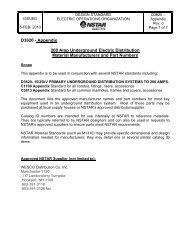
NSTAR <strong>ELECTRIC</strong> DISTRICTS<br />
North District<br />
South District<br />
Cambridge District<br />
Downtown Boston Network District<br />
South District<br />
Acushnet<br />
Aquinnah<br />
Barnstable<br />
Bourne<br />
Brewster<br />
Carver<br />
Chatham<br />
Chilmark<br />
Dartmouth<br />
Dennis<br />
Duxbury<br />
Eastham<br />
Edgartown<br />
Fairhaven<br />
Falmouth<br />
Freetown<br />
Harwich<br />
Kingston<br />
Lakeville<br />
Marion<br />
Marshfield<br />
Mashpee<br />
Mattapoisett<br />
New Bedford<br />
Oak Bluffs<br />
Orleans<br />
Pembroke<br />
Plymouth<br />
Plympton<br />
Provincetown<br />
Rochester<br />
Sandwich<br />
Scituate<br />
(Humarock)<br />
Tisbury<br />
Truro<br />
Wareham<br />
Wellfleet<br />
Westport<br />
West Tisbury<br />
Yarmouth<br />
NSTAR <strong>ELECTRIC</strong> DISTRICTS<br />
North District<br />
Acton<br />
Medway<br />
Allston Millis<br />
Arlington Milton<br />
Ashland Natick<br />
Bedford Needham<br />
Bellingham Newton<br />
Brighton Norfolk<br />
Brookline Roslindale<br />
Burlington Roxbury<br />
Canton Sharon<br />
Carlisle Sherborn<br />
Chelsea Somerville<br />
Dedham S. Boston<br />
Dorchester Stoneham<br />
Dover<br />
Sudbury<br />
East Boston Walpole<br />
Framingham Waltham<br />
Holliston Watertown<br />
Hopkinton Wayland<br />
Hyde Park Weston<br />
Jamaica Plain West Roxbury<br />
Lexington Westwood<br />
Lincoln Winchester<br />
Mattapan Woburn<br />
Maynard<br />
Medfield<br />
2<br />
Cambridge<br />
District<br />
Cambridge<br />
Downtown<br />
Boston Network<br />
District<br />
Back Bay<br />
Boston<br />
Charlestown<br />
Fenway<br />
South End<br />
3
CHECKLIST<br />
A CHECKLIST TO GUIDE YOU TO PROMPT AND<br />
EFFICIENT <strong>SERVICE</strong><br />
Sometimes, even the most important pieces of the electric service<br />
process may get overlooked. To help you determine if you’ve<br />
covered all the bases when it comes to getting your electric service<br />
energized, we have created the following checklist of items. Their<br />
corresponding sections in this handbook also appear for more<br />
detailed information.<br />
• Work Order Application completed (form at<br />
www.nstar.com)<br />
• Outside location of meters (Article 704)<br />
• Proper meter sockets in place (Article 715)<br />
• Cold sequenced meters (Article 705)<br />
• Two or more meters (Article 708)<br />
• “Identification of Meter Sockets” form completed (Article 708)<br />
• Are multi-sockets properly marked (Article 708)<br />
• Does a clear cover plate exist for wired sockets pending<br />
installation of a meter (Article 716)<br />
• Correct service attachment hardware installed (Sketch 5)<br />
• Fees paid (Article 206 & current fees available with the<br />
Work Order Application form at www.nstar.com)<br />
• Obtained wire inspector approval (Article 207)<br />
TABLE OF CONTENTS<br />
TABLE OF CONTENTS<br />
Introduction . . . . . . . . . . . . . . . . . . . . . . . . . . . . . . . . . . . . . . . . .1<br />
NSTAR Electric Districts . . . . . . . . . . . . . . . . . . . . . . . . . . . . . . . .2<br />
Electric Service Checklist . . . . . . . . . . . . . . . . . . . . . . . . . . . . . . .4<br />
Contact Us . . . . . . . . . . . . . . . . . . . . . . . . . . . . . . . . . . . . . . . . . . .11<br />
Safety Requirements . . . . . . . . . . . . . . . . . . . . . . . . . . . . . . . . . .12<br />
Frequently Asked Questions . . . . . . . . . . . . . . . . . . . . . . . . . . .14<br />
Utility Authorization Process . . . . . . . . . . . . . . . . . . . . . . . . . .17<br />
Article 100 General Information . . . . . . . . . . . . . . . . . . . . . . . .18<br />
101. Introduction . . . . . . . . . . . . . . . . . . . . . . . . . . . . . . . .18<br />
102. Scope . . . . . . . . . . . . . . . . . . . . . . . . . . . . . . . . . . . . .18<br />
103. Uniform Requirements . . . . . . . . . . . . . . . . . . . . . . . . .18<br />
104. Effective Date . . . . . . . . . . . . . . . . . . . . . . . . . . . . . . .18<br />
105. Enforcement of Rules . . . . . . . . . . . . . . . . . . . . . . . . . .19<br />
106. Special Circumstances . . . . . . . . . . . . . . . . . . . . . . . . .20<br />
107. Advisory Service . . . . . . . . . . . . . . . . . . . . . . . . . . . . .20<br />
108. Rates . . . . . . . . . . . . . . . . . . . . . . . . . . . . . . . . . . . . .20<br />
109. Information . . . . . . . . . . . . . . . . . . . . . . . . . . . . . . . . .21<br />
110. Diversion of Electrical Energy . . . . . . . . . . . . . . . . . . . .22<br />
111. Cities and Towns Served; City/Town (Inspector of Wires<br />
Information) . . . . . . . . . . . . . . . . . . . . . . . . . . . . . . .22<br />
Article 200 Application for New or Additional Service . .29<br />
201.Where to Apply . . . . . . . . . . . . . . . . . . . . . . . . . . . . . .29<br />
202.When to Apply . . . . . . . . . . . . . . . . . . . . . . . . . . . . . .29<br />
203. Availability of Service . . . . . . . . . . . . . . . . . . . . . . . . . .30<br />
204. Additional Loads . . . . . . . . . . . . . . . . . . . . . . . . . . . . .30<br />
4 5
TABLE OF CONTENTS<br />
205. Relocation or Alteration of Service . . . . . . . . . . . . . . . .30<br />
206. Customer Cost . . . . . . . . . . . . . . . . . . . . . . . . . . . . . .31<br />
207. Inspection Certificates . . . . . . . . . . . . . . . . . . . . . . . . .31<br />
208.Temporary Service and Installation Charges . . . . . . . . . . .31<br />
209. Disconnecting and Reconnecting Overhead or<br />
Underground Electric Services . . . . . . . . . . . . . . . . . . .32<br />
210. Moving of Buildings or Structures . . . . . . . . . . . . . . . . .32<br />
211. Company Liability . . . . . . . . . . . . . . . . . . . . . . . . . . . .32<br />
212. Resale of Energy . . . . . . . . . . . . . . . . . . . . . . . . . . . . .33<br />
Article 300 General Services . . . . . . . . . . . . . . . . . . . . . . . . .33<br />
301. Availability of Service . . . . . . . . . . . . . . . . . . . . . . . . . .33<br />
302. Number of Services . . . . . . . . . . . . . . . . . . . . . . . . . . .33<br />
303. Service Characteristics . . . . . . . . . . . . . . . . . . . . . . . . .34<br />
304. Customer Requirements . . . . . . . . . . . . . . . . . . . . . . . .37<br />
305. Customer Generation . . . . . . . . . . . . . . . . . . . . . . . . . .37<br />
306.Voltage Sensitive Equipment . . . . . . . . . . . . . . . . . . . . .40<br />
307. Secondary Lightning Arresters . . . . . . . . . . . . . . . . . . . .40<br />
308. Short Circuit Currents . . . . . . . . . . . . . . . . . . . . . . . . .40<br />
309. Unbalanced Load . . . . . . . . . . . . . . . . . . . . . . . . . . . . .41<br />
Article 400 Installation of Services Policies,<br />
Rights and Permits . . . . . . . . . . . . . . . . . . . . . . . . . . . . . . . . . 41<br />
401. Public Grants and Special Permits . . . . . . . . . . . . . . . . .41<br />
402. Private Property Permits and Crossing . . . . . . . . . . . . . .41<br />
403. Extension of Lines In The Public Way . . . . . . . . . . . . . . .42<br />
404. Ownership of Private Residential Overhead Construction . .44<br />
405. Underground Service Credit . . . . . . . . . . . . . . . . . . . . .46<br />
406.When Customers Install Their Own Electric Service Facilities .46<br />
6<br />
TABLE OF CONTENTS<br />
407. Policy on Connections . . . . . . . . . . . . . . . . . . . . . . . .47<br />
408.Violations . . . . . . . . . . . . . . . . . . . . . . . . . . . . . . . . .48<br />
Overhead Services . . . . . . . . . . . . . . . . . . . . . . . . . . . . . . . . .48<br />
409. Lines of Demarcation for Overhead Service . . . . . . . . . .48<br />
410. Overhead Span Distances . . . . . . . . . . . . . . . . . . . . . .48<br />
411. Point of Attachment . . . . . . . . . . . . . . . . . . . . . . . . . .48<br />
412. Overhead Clearances . . . . . . . . . . . . . . . . . . . . . . . . .49<br />
413. Overhead Secondary Services . . . . . . . . . . . . . . . . . . .49<br />
414. Overhead Primary Service . . . . . . . . . . . . . . . . . . . . . .52<br />
Underground Secondary Services . . . . . . . . . . . . . . . . . . .54<br />
415. Lines of Demarcation . . . . . . . . . . . . . . . . . . . . . . . . .54<br />
416. Size . . . . . . . . . . . . . . . . . . . . . . . . . . . . . . . . . . . . .54<br />
417. Point of Attachment and Minimum Conductor Lengths . .54<br />
418.Trench for Underground Service . . . . . . . . . . . . . . . . .55<br />
419. Service Conduits on Private Property . . . . . . . . . . . . . .56<br />
420. Conduit Installations - Minimum Specifications . . . . . . .56<br />
421. Handholes or Manholes on Private Property . . . . . . . . .57<br />
422. Underground Developments . . . . . . . . . . . . . . . . . . . .57<br />
423. Underground Secondary Service from<br />
NSTAR Overhead Line . . . . . . . . . . . . . . . . . . . . . . . .59<br />
Underground Services from Underground<br />
Distribution System . . . . . . . . . . . . . . . . . . . . . . . . . . . . . . . .60<br />
424. Underground Secondary Services from Underground<br />
Distribution System . . . . . . . . . . . . . . . . . . . . . . . . . .60<br />
425. Installation of Underground Service When Construction is<br />
Required on Private Property . . . . . . . . . . . . . . . . . . .61<br />
7
TABLE OF CONTENTS<br />
426. Customer-Elected Installation of Underground Service on<br />
Private Property . . . . . . . . . . . . . . . . . . . . . . . . . . . .61<br />
427. Underground Connections . . . . . . . . . . . . . . . . . . . . .61<br />
428.Terminal Facilities/Terminal Boxes . . . . . . . . . . . . . . . .62<br />
429. Grounding and Bonding . . . . . . . . . . . . . . . . . . . . . . .63<br />
430. Pole-Mounted Transformers . . . . . . . . . . . . . . . . . . . .63<br />
431. Mat and Fence Substation . . . . . . . . . . . . . . . . . . . . . .63<br />
432. Padmount Transformer . . . . . . . . . . . . . . . . . . . . . . . .64<br />
433. Building Vault . . . . . . . . . . . . . . . . . . . . . . . . . . . . . .67<br />
Article 500 General Service Requirements . . . . . . . . . . . .68<br />
501. Customer-Owned Equipment . . . . . . . . . . . . . . . . . . .68<br />
502. Load Balance . . . . . . . . . . . . . . . . . . . . . . . . . . . . . . .68<br />
503. Separate Services . . . . . . . . . . . . . . . . . . . . . . . . . . . .68<br />
504. Size of Conduits and Conductors . . . . . . . . . . . . . . . . .69<br />
505. Service Equipment . . . . . . . . . . . . . . . . . . . . . . . . . . .69<br />
506. Assigning Location of Service and Metering Equipment . .69<br />
507. Unmetered Conductors . . . . . . . . . . . . . . . . . . . . . . .70<br />
508. Metered Conductors . . . . . . . . . . . . . . . . . . . . . . . . .70<br />
509. Overcurrent Protection of Feeders . . . . . . . . . . . . . . . .70<br />
510. Fuses . . . . . . . . . . . . . . . . . . . . . . . . . . . . . . . . . . . .70<br />
511. Bonding Service Equipment: Secondary Services . . . . . .70<br />
512.Temporary Service . . . . . . . . . . . . . . . . . . . . . . . . . . .71<br />
Article 600 Wiring and.Requirements . . . . . . . . . . . . . . . . .72<br />
601. Signs and Automatically Controlled Lighting . . . . . . . . .72<br />
602. Fluctuating Loads . . . . . . . . . . . . . . . . . . . . . . . . . . . .72<br />
603. Grounding . . . . . . . . . . . . . . . . . . . . . . . . . . . . . . . . .72<br />
TABLE OF CONTENTS<br />
604. Insulating Transformers (sometimes referred to as isolating<br />
transformers) . . . . . . . . . . . . . . . . . . . . . . . . . . . . . .72<br />
605. Power Factor . . . . . . . . . . . . . . . . . . . . . . . . . . . . . . .73<br />
606. Power Factor Correction Capacitors . . . . . . . . . . . . . . .74<br />
607. Power Supply to Voltage Sensitive Equipment . . . . . . . .74<br />
608. Power Quality . . . . . . . . . . . . . . . . . . . . . . . . . . . . . .75<br />
Article 700 Meters General Requirements . . . . . . . . . . . . .75<br />
701. General . . . . . . . . . . . . . . . . . . . . . . . . . . . . . . . . . . .75<br />
702. Meter Tampering . . . . . . . . . . . . . . . . . . . . . . . . . . . .76<br />
703. Standard Meter Installations . . . . . . . . . . . . . . . . . . . . .77<br />
704. Meter Locations . . . . . . . . . . . . . . . . . . . . . . . . . . . . .77<br />
A. Outdoor Meters<br />
B. Indoor Meters<br />
705. Location of Service Disconnect and Current<br />
Limiting Protection . . . . . . . . . . . . . . . . . . . . . . . . . .79<br />
A. Hot Sequence<br />
B. Cold Sequence<br />
C. Current Limiting Protection<br />
706. Meter Mounting . . . . . . . . . . . . . . . . . . . . . . . . . . . . .80<br />
707. Clearances . . . . . . . . . . . . . . . . . . . . . . . . . . . . . . . . .81<br />
708. Identification of Meter Sockets and Customer Disconnecting<br />
Means for Multiple Meter Installations . . . . . . . . . . . . .81<br />
709. Moving or Removing Metering Equipment . . . . . . . . . .82<br />
710. Meter Connections . . . . . . . . . . . . . . . . . . . . . . . . . .82<br />
711. Security . . . . . . . . . . . . . . . . . . . . . . . . . . . . . . . . . .82<br />
A. For Single Phase 3 wire, services<br />
B. Meter Seals<br />
8<br />
9
TABLE OF CONTENTS<br />
712. Meter Accessories . . . . . . . . . . . . . . . . . . . . . . . . . . .84<br />
A.Telephone Line for Interval Data Metering Applications<br />
B. Optional Enhanced Metering Service<br />
Meter Sockets . . . . . . . . . . . . . . . . . . . . . . . . . . . . . . . . . . . . .84<br />
715. Meter Sockets for Self-Contained Meters . . . . . . . . . . .84<br />
A. Sockets with Manual Bypass<br />
B. 200 Amperes or Less<br />
C. 400 Amperes or Less (320 Amperes continuous Load Capacity)<br />
D. Sockets for 200 Amperes or Less Residential or<br />
Commercial Underground Services<br />
716. Cover Plates . . . . . . . . . . . . . . . . . . . . . . . . . . . . . . .87<br />
Instrument Transformer Installation . . . . . . . . . . . . . . . . .87<br />
720. Instrument Transformers and Enclosures . . . . . . . . . . . .87<br />
721. Use of Instrument Transformer Cabinets . . . . . . . . . . . .89<br />
722. Pad-Mount Metering . . . . . . . . . . . . . . . . . . . . . . . . .89<br />
723. Primary Metering . . . . . . . . . . . . . . . . . . . . . . . . . . .91<br />
Metal-Enclosed Bus Duct - 600 Volts or Less . . . . . . . . . . .91<br />
730. General . . . . . . . . . . . . . . . . . . . . . . . . . . . . . . . . . .91<br />
Metal-Enclosed Switchgear Over 600 Volts . . . . . . . . . . . .92<br />
740. General . . . . . . . . . . . . . . . . . . . . . . . . . . . . . . . . . .92<br />
Article 800 Utilization Equipment . . . . . . . . . . . . . . . . . . .92<br />
801. General . . . . . . . . . . . . . . . . . . . . . . . . . . . . . . . . . .92<br />
802. Nameplate Data . . . . . . . . . . . . . . . . . . . . . . . . . . . . .92<br />
A. Definitions and Notes<br />
B. Limitation of Motor Size<br />
C. Single Phase Motors<br />
D.Three phase Motors<br />
E. Supply Voltage- Special<br />
10<br />
CONTACT US<br />
803. Motor Protection . . . . . . . . . . . . . . . . . . . . . . . . . . . .99<br />
804. Fluctuating Loads . . . . . . . . . . . . . . . . . . . . . . . . . . .100<br />
Article 900 Radio,Television, CATV & Carrier Installations . .101<br />
901. Operation . . . . . . . . . . . . . . . . . . . . . . . . . . . . . . . .101<br />
902. Installation of Eliminator or Trap . . . . . . . . . . . . . . . .102<br />
903. Service Quality Requirements . . . . . . . . . . . . . . . . . .102<br />
904. Prohibition of Attachment to Poles . . . . . . . . . . . . . . .102<br />
905. Clearance from Company Conductors . . . . . . . . . . . .102<br />
906. Carrier Equipment . . . . . . . . . . . . . . . . . . . . . . . . . .102<br />
907. Community Antenna Television (CATV) Systems . . . . .103<br />
908. Cellular Telephone Towers . . . . . . . . . . . . . . . . . . . . .103<br />
909.Town Owned Street Lights . . . . . . . . . . . . . . . . . . . .103<br />
Appendix A Sketch Index and Sketches . . . . . . . . . . . . .104<br />
Appendix B Massachusetts General Laws . . . . . . . . . . . .138<br />
CONTACT US<br />
During regular business hours (Monday thru Friday, 7:30 a.m. to<br />
4:30 p.m.) please call 1-888-NEEDPWR (1-888-633-3797) to speak<br />
with the NSTAR New Customer Connect Tech Center.<br />
Mailing address:<br />
NSTAR Electric<br />
One NSTAR Way<br />
Westwood, MA 02090-9230<br />
Attention: NSTAR New Customer Connect Tech Center<br />
You can also reach us online at www.nstar.com.<br />
11
SAFETY <strong>REQUIREMENTS</strong><br />
SAFETY <strong>REQUIREMENTS</strong><br />
NSTAR has a number of requirements and tips to ensure your<br />
safety. Please make sure to read the following safety requirement<br />
highlights, and look for more throughout this booklet.<br />
• The covering you may observe on some overhead<br />
electrical wires is not insulation, so please do not touch it.<br />
Any contact with our wires may cause serious injury or<br />
death. Upon request, NSTAR will install line-hose guards<br />
or erect other mechanical barriers to help protect against<br />
contact with electrical lines. In some cases, customer<br />
charges will apply for installation of line-hose guards.<br />
• Heavy construction equipment such as cranes, derricks,<br />
backhoes, dump trucks, etc. should not be operated closer<br />
than 10 feet from energized power lines rated at 50 kV or<br />
below. For lines rated over 50 kV, the minimum clearance<br />
between the lines and any part of the equipment shall be<br />
10 feet plus 0.4 inches for each kV over 50 kV as<br />
prescribed by OSHA Regulations (S1926 subpart N-550-<br />
(a) 15 (i) and (ii)).<br />
• Massachusetts General Laws, Chapter 166, Sections 21A-<br />
21G govern work in close proximity to high voltage lines.<br />
NSTAR strongly recommends that a minimum clearance of<br />
10 feet be maintained.<br />
• Swimming pools should not be installed beneath overhead<br />
facilities. Please contact NSTAR if you are planning to<br />
install a pool near overhead or underground lines.You can<br />
also check out the National and Massachusetts Electric<br />
Codes for clearance information.<br />
SAFETY <strong>REQUIREMENTS</strong><br />
• In general, antennas, banners, signs or similar customer<br />
equipment shall not be attached to our poles except by<br />
special permission from NSTAR. Such equipment when<br />
installed nearby shall be far enough away so contact with<br />
our facilities cannot take place during installation, removal,<br />
or by accident. All clearances shall be as required by State<br />
and National Safety Codes.<br />
• To safeguard both your property and NSTAR, fuses or<br />
breakers or those of branch circuits should only be<br />
replaced with the proper size fuse or breakers for such<br />
installation. Please contact NSTAR for additional<br />
information.<br />
• Consider adding ground fault interrupters to existing<br />
circuits as prescribed by the Massachusetts Electrical Code.<br />
12<br />
13
FREQUENTLY ASKED QUESTIONS<br />
FREQUENTLY ASKED QUESTIONS<br />
1. Do I need an NSTAR authorization number before<br />
work begins<br />
Yes,You must obtain a utility authorization number before<br />
NSTAR can perform any electric service work.<br />
Please contact the NSTAR New Customer Connect Tech<br />
Center at 888-NEED-PWR (1-888-633-3797) to get that<br />
authorization number.<br />
2. Do I need City/Town written approval for<br />
installations<br />
For all installations (new, upgraded, relocated or repaired), you<br />
need to get written approval from what is called the “authority<br />
having jurisdiction” before any service will be energized.This is<br />
usually a state, city or federal authority, depending on the area.<br />
3. Where do I install a meter socket<br />
All meter sockets (commercial, industrial, and residential) are<br />
installed outside at a pre-approved location that NSTAR and<br />
the customer agree upon. At multi-meter locations, all meter<br />
sockets must be properly marked with the floor and suite<br />
number. NSTAR cannot energize installations that are<br />
incorrectly marked, or not marked at all.<br />
4. Where is a disconnect switch installed<br />
Disconnect switches are located on the line side of the<br />
individual meter socket (cold sequence metering) for the<br />
following applications:<br />
• On all ampere services on 480 volt three wire and<br />
277/480 volt four wire installations<br />
• For instrument transformer installations refer to article 720<br />
FREQUENTLY ASKED QUESTIONS<br />
Disconnect switches in all applications must be in close<br />
proximity and within sight to each meter socket. Consult<br />
NSTAR and the local inspection authority for specific<br />
installation requirements.<br />
5. Who performs permanent connections<br />
On all service upgrades or replacement of damaged service<br />
entrance cables, the electrician makes permanent connections<br />
on all overhead services at the weather head and on all<br />
underground services in the terminal box.<br />
6. Who installs terminal boxes<br />
The electrician installs all terminal boxes required for<br />
underground services. If the service is energized, NSTAR will<br />
disconnect and reconnect the service upon customer request.<br />
Receipt of approval by the authority having jurisdiction will be<br />
required before the service can be re-energized. Massachusetts<br />
Electric Code governs the size of the terminal box.<br />
7. Where is a customer’s weatherhead supposed to be<br />
located<br />
The customer’s weatherhead shall be located above NSTAR’s<br />
point of attachment.<br />
8. What type of conduit is required for service<br />
installations<br />
For a mast installation, a minimum size 2 inch rigid metal<br />
conduit is required. Also, no other utility can be connected to<br />
this conduit.<br />
9. What connectors are required for copper to<br />
aluminum connections<br />
Bi-metal connectors are required on all copper to aluminum<br />
connections.<br />
14 15
FREQUENTLY ASKED QUESTIONS<br />
10. At what height should the meter socket be mounted<br />
The minimum meter height from the finished grade is three feet<br />
to the center of the meter socket.The maximum height is six<br />
feet to the center of the meter socket.<br />
11. What material do I use for a riser pole section<br />
Once you have approval from the authority having jurisdiction,<br />
you can use minimum 3 inch schedule 80 PVC or rigid metal<br />
conduit for a riser pipe section on the utility pole. Please note, if<br />
rigid metal conduit is used a grounding bushing is required to be<br />
installed with the wire lead connected to the system ground.<br />
12. For Three phase, three wire installations what meter<br />
socket should be used<br />
For a three phase, three wire installation, a five-jaw meter<br />
socket with an approved bar-type bypass is required.This socket<br />
is designed to break A & C phases only. The fifth terminal must<br />
be permanently attached to B phase at the six o’clock position.<br />
13. When do I need a meter socket by-pass<br />
A By-pass is currently required in all non-residential meter<br />
sockets regardless of ampacity.<br />
14. If I cannot meet one of the requirements in this<br />
manual, what should I do<br />
If you feel you cannot meet one or more of the requirements in<br />
this handbook, you may request exemption. Requests for<br />
exemptions should be formally submitted in writing to the<br />
NSTAR New Customer Connect Tech Center. Please include:<br />
• A reference to the specific requirement and corresponding<br />
article number<br />
• The exemption you need<br />
• The reason for the exemption.<br />
UTILITY AUTHORIZATION PROCESS<br />
UTILITY AUTHORIZATION PROCESS<br />
Early contact with the NSTAR New Customer Connect Tech<br />
Center will assure that construction, service connections and<br />
metering are performed within the requested in-service date.<br />
Please be ready to provide complete customer name and service<br />
address information, load and technical requirements to obtain the<br />
necessary utility authorization number when requesting service.<br />
If construction is required (i.e. a new service drop, new or<br />
additional transformation, etc.), engineering designs are reviewed<br />
and completed during this stage.<br />
The service request will be approved by NSTAR’s engineering<br />
group with any required rights and/or easements researched and<br />
obtained.The NSTAR New Customer Connect Tech Center will<br />
approve and collect any required customer charges.<br />
To check the status of a work order during any stage in the utility<br />
authorization process, please call the NSTAR New Customer<br />
Connect Tech Center at 888-633-3797.<br />
Receipt of approval by the authority having jurisdiction, (federal,<br />
state, and/or city) in addition to any customer charges, releases a<br />
utility authorization to the field for construction and the<br />
installation of metering equipment. Approval can be in the form<br />
of a City/Town wiring permit, or a letter of approval by the<br />
appropriate federal or state inspectional authority.<br />
16<br />
17
ARTICLE 100-104<br />
ARTICLE 100 GENERAL <strong>INFORMATION</strong><br />
101. Introduction<br />
The Information and Requirements for Electric Service<br />
booklet is issued to provide a thorough understanding between<br />
NSTAR and its customers, architects, builders, electrical<br />
contractors, consulting engineers and municipal inspectors. It<br />
is also important to stay up to date on NSTAR’s Schedule of<br />
Rates and its Terms and Conditions, as they are filed from time<br />
to time with the Massachusetts Department of Public Utilities<br />
(DPU) and which are subject to change.<br />
102. Scope<br />
The information contained in this booklet applies primarily to<br />
electric service requirements for installations not exceeding<br />
480 volts. Service requirements for installations at higher<br />
voltages are subject to special negotiations with the NSTAR<br />
New Customer Connect Tech Center.<br />
103. Uniform Requirements<br />
Many of NSTAR’s requirements are the same as those of other<br />
electric utilities that serve cities and towns in adjoining<br />
territories. However, differences in some requirements do<br />
exist.To avoid misunderstanding, it is essential that a copy of<br />
the local electric utility company’s requirements be obtained<br />
and followed when work is to be done in its territory.<br />
104. Effective Date<br />
This issue of Information and Requirements for Electric<br />
Service supersedes all previous issues for NSTAR Electric,<br />
Boston Edison, COMElectric and Cambridge Electric and is<br />
effective immediately for all new construction, with reasonable<br />
allowance for the completion of work in progress or already<br />
under contract. NSTAR reserves the right to revise, alter,<br />
amend, add or repeal this information when necessary or<br />
18<br />
ARTICLE 105<br />
appropriate and will endeavor to notify all interested persons.<br />
It will be incumbent upon all interested persons to keep<br />
themselves informed as to such revisions, alterations,<br />
amendments, additions or repeals. NSTAR assumes no<br />
responsibility to notify persons relative to such revisions,<br />
alterations, amendments, additions or repeals.<br />
105. Enforcement of Rules<br />
All wiring intended for connection to the electrical conductors<br />
of NSTAR shall be in accordance with requirements of the<br />
authority having jurisdiction, the Massachusetts Electrical Code<br />
and of NSTAR. Service connection to new customer wiring<br />
installations will not be made until notice of approval of the<br />
new wiring is received from the authority having jurisdiction.<br />
All connections to NSTAR’s system shall be designed, installed<br />
and operated in a manner that will not cause undue<br />
disturbance to other customers, and will not restrict NSTAR<br />
from maintaining proper system conditions. NSTAR reserves<br />
the right to de-energize the service of any customer who, after<br />
proper notice from NSTAR, continues to use any equipment or<br />
apparatus that adversely affects the service of other customers<br />
or any service that has not received approval from the<br />
authority having jurisdiction.<br />
In those instances where the electrician has not satisfactorily<br />
fulfilled the requirements as stated in this manual, designated<br />
employees of NSTAR will, upon receiving approval from the<br />
customer, correct any omission or improper installation.<br />
A charge for any services rendered will be forwarded to the<br />
customer for payment.<br />
In those instances where the electrician has not satisfactorily<br />
fulfilled the requirement as stated in the Massachusetts<br />
19
ARTICLE 106-108<br />
Electrical Code, designated employees of NSTAR will, upon<br />
receiving approval from both the authority having jurisdiction<br />
and the customer, correct any omission or improper<br />
installation. A notice of violation will be sent to the<br />
electrician, the authority having jurisdiction and the customer.<br />
A charge for any services rendered will be forwarded to the<br />
customer for payment.<br />
Any substantial changes shall be rectified by the electrician and<br />
inspected by the authority having jurisdiction before any<br />
service will be energized.<br />
106. Special Circumstances<br />
NSTAR reserves the right to waive these requirements in<br />
special circumstances where conditions warrant. Any waiver of<br />
these requirements will be in writing and will not be<br />
considered as establishing a precedent nor be considered as<br />
affecting NSTAR’s right to enforce any of the other<br />
requirements as outlined in this manual.<br />
107. Advisory Service<br />
NSTAR will actively cooperate with architects, contractors and<br />
engineers. However, neither by inspection nor by the rendering<br />
of advisory service nor in any other way does NSTAR give any<br />
warranty, expressed or implied, as to the adequacy, safety or<br />
other characteristics of any equipment, wires, appliances or<br />
devices owned, used or maintained by customers.<br />
108. Rates<br />
NSTAR furnishes its various services under tariffs and/or<br />
contracts (“Schedule of Rates”) promulgated in accordance<br />
with the provisions of M.G.L.c. 164, and MDPU decisions,<br />
orders and regulations. Copies of Rate Schedules are available<br />
upon request or from NSTAR’s website at www.nstar.com.<br />
ARTICLE 109<br />
NSTAR shall provide notice regarding its applicable rate<br />
schedules annually to all customers. NSTAR shall advise each<br />
new non-residential customer of the least expensive rate for<br />
distribution service based on available information in NSTAR’s<br />
existing records or as a result of a field inspection by NSTAR<br />
when the customer provides information that is inconsistent<br />
with NSTAR’s records. Upon receipt of adequate information<br />
concerning rates, selection of the rate is the responsibility of<br />
the customer. Each customer is responsible for accurately<br />
describing his or her electrical needs and equipment and for<br />
providing NSTAR with updated information as changes occur.<br />
Each customer is entitled to change from one applicable<br />
Distribution Service rate schedule to another upon written<br />
application to NSTAR. Any customer who has changed from<br />
one Distribution Service rate to another may not change again<br />
within one (1) year or a longer period as specified in the tariff<br />
under which the customer is receiving distribution service. A<br />
change in rate that is requested by the customer will not<br />
necessarily produce a retroactive billing adjustment.<br />
109. Information<br />
The NSTAR New Customer Connect Tech Center coordinates<br />
all discussions with commercial, industrial, governmental and<br />
residential customers regarding electric service.The NSTAR<br />
New Customer Connect Tech Center shall provide information<br />
regarding NSTAR service policy, rate application, service<br />
request, status of service request, availability of service, service<br />
requirements, and applicable service charges to all customers.<br />
Please call 888-633-3797 for additional information.<br />
20<br />
21
ARTICLE 110-111<br />
110. Diversion of Electrical Energy<br />
A diversion of electrical energy is any method or device<br />
used by any person that prevents an electric meter from<br />
duly registering the quantity of electricity supplied by<br />
NSTAR and/or any taking of any electrical current without<br />
NSTAR’s consent.<br />
Where there is evidence of meter tampering or theft of<br />
electrical energy, such person or persons responsible shall<br />
be liable for prosecution under penalty of Massachusetts<br />
General Laws:<br />
22<br />
Chapter 164, Section 127 & 127A<br />
Chapter 166, Section 38<br />
Extracts from the above General Laws are printed<br />
in this booklet in Appendix B.<br />
111. Cities and Towns Served City/Town Inspector of<br />
Wires Information<br />
The following is a list of the cities and towns served by<br />
NSTAR in which these requirements apply. Addresses and<br />
telephone numbers of the city/town halls and the<br />
appropriate inspector or wires telephone numbers have<br />
been included for your convenience.<br />
CITIES AND TOWNS SERVED<br />
City/Town City/Town Hall Inspector of Wires<br />
Address & Telephone Telephone<br />
ACTON<br />
472 Main Street<br />
(978) 486-0167 (978) 486-0167<br />
ACUSHNET 122 Main Street<br />
(508) 998-0200 (508) 998-0025<br />
AQUINNAH 65 State Road<br />
(508) 645-2300 (508) 645-2300<br />
ARLINGTON 730 Mass Avenue<br />
(781) 316-3000 (781) 316-3393<br />
ASHLAND 101 Main Street<br />
(508) 881-0100 (508) 881-0117<br />
BARNSTABLE 200 Main Street<br />
(508) 862-4000 (508) 862-4089<br />
BEDFORD 10 Mudge Way<br />
(781) 275-1111 (781) 275-7446<br />
BELLINGHAM 4 Mechanic Street<br />
(508) 966-5800 (508) 657-2856<br />
BOSTON<br />
1 City Hall Plaza<br />
(617) 635-4000 (617) 635-5300<br />
BOURNE<br />
24 Perry Avenue<br />
(508) 759-0600 (508) 759-0615<br />
BREWSTER 2198 Main Street<br />
(508) 896-3701 (508) 896-3701 X127<br />
BROOKLINE 333 Washington Street<br />
(617) 730-2200 (617) 730-2110<br />
BURLINGTON 29 Center Street<br />
(781) 270-1615 (781) 270-1753<br />
CAMBRIDGE 795 Mass Ave Fl 1<br />
(617) 349-4000 (617)-349-6100<br />
CANTON 801 Washington Street<br />
(781) 821-5000 (781) 821-5003<br />
23
CITIES AND TOWNS SERVED<br />
CITIES AND TOWNS SERVED<br />
City/Town City/Town Hall Inspector of Wires<br />
Address & Telephone Telephone<br />
CARLISLE 66 Westford Street<br />
(978) 369-6155 (978) 369-6689<br />
CARVER<br />
108 Main Street<br />
(508) 866-3400 (508) 866-3405<br />
CHATHAM 549 Main Street<br />
(508) 945-5160 (508) 945-5160<br />
CHELSEA 500 Broadway<br />
(617) 466-4000 (617) 466-4130<br />
CHILMARK PO Box 119<br />
(508) 645-2100 (508) 696-6400<br />
DARTMOUTH 400 Slocum Rd.<br />
(508) 910-1800 (508) 910-1889<br />
DEDHAM 26 Bryant Street<br />
(781) 751-9200 (781) 751-9180<br />
DENNIS<br />
485 Main Street<br />
(508) 394-8300 (508) 760-6157<br />
DOVER<br />
5 Springdale Avenue<br />
(508) 785-0032 (508) 785-0032 X245<br />
DUXBURY 878 Tremont Street<br />
(781) 934-1100 (781) 934-1100<br />
EASTHAM 2500 State Highway<br />
(508) 240-5900 (508) 240-5900 X233<br />
EDGARTOWN 70 Main Street<br />
(508) 627-6180 (508) 627-6115<br />
FAIRHAVEN 40 Centre Street<br />
(508) 979-4023 (508) 979-4019<br />
FALMOUTH 59 Town Hall Square<br />
(508) 548-7611 (508) 495-7473<br />
FRAMINGHAM 150 Concord Street<br />
(508) 532-5500 (508) 532-5520<br />
City/Town City/Town Hall Inspector of Wires<br />
Address & Telephone Telephone<br />
FREETOWN PO Box 438 Assonet MA<br />
(508) 644-2201 (508) 644-2202<br />
HARWICH 732 Main Street<br />
(508) 430-7513 (508) 430-7507<br />
HOLLISTON 703 Washington Street<br />
(508) 429-0608 (508) 429-0606<br />
HOPKINTON 18 Main Street<br />
(508) 497-9700 (508) 497-9745<br />
KINGSTON 26 Evergreen Street<br />
(781) 585-0500 (781) 585-0505<br />
LAKEVILLE 346 Bedford Street<br />
(508) 946-8800 (508) 947-6571<br />
LEXINGTON 1625 Mass Avenue<br />
(781) 862-0500 (781) 862-0500 X215<br />
LINCOLN 16 Lincoln Road<br />
(781) 259-2600 (781) 259-2613<br />
MARION<br />
2 Spring Street<br />
(508) 748-3500 (508) 748-3516<br />
MARSHFIELD 870 Moraine Street<br />
9781) 834-5563 (781) 834-5555<br />
MASHPEE 16 Great Neck Road<br />
(508) 539-1400 (508) 539-1400<br />
MATTAPOISETT PO Box 435<br />
(508) 758-4100 (508) 758-4100<br />
MAYNARD 195 Main Street<br />
(978) 897-1001 (978) 897-8015<br />
MEDFIELD 459 Main Street<br />
(508) 359-8505 (508) 359-8505 X603<br />
MEDWAY 155 Village Street<br />
(508) 533-3200 (508) 533-3253<br />
24 25
CITIES AND TOWNS SERVED<br />
City/Town City/Town Hall Inspector of Wires<br />
Address & Telephone Telephone<br />
MILLIS<br />
900 Main Street<br />
(508) 376-7040 (508) 376-7044<br />
MILTON<br />
525 Canton Avenue<br />
(617) 898-4878 (617) 898-4900<br />
NATICK<br />
13 East Central Street<br />
(508) 647-6400 (508) 647-6450<br />
NEEDHAM 1471 Highland Avenue<br />
(781) 455-7500 (781) 455-7542 X210<br />
NEW BEDFORD 133 William Street<br />
(508) 979-1400 (508) 979-1470<br />
NEWTON 1000 Commonwealth Ave.<br />
(617) 796-1000 (617) 796-1075<br />
NORFOLK One Liberty Lane<br />
(508) 528-1408 (508) 528-5088<br />
OAK BLUFFS PO Box 1327<br />
(508) 693-3554 (508) 693-3554<br />
ORLEANS 19 School Road<br />
(508) 240-3700 (508) 240-3700 X343<br />
PEMBROKE 100 Center Street<br />
(781) 293-3844 (781) 293-3864<br />
PLYMOUTH 11 Lincoln Street<br />
(508) 747-1620 (508) 747-1620<br />
PROVINCETOWN 260 Commercial Street<br />
(508) 487-7000 (508) 487-7000 X520<br />
ROCHESTER 1 Constitution Way<br />
(508) 763-3871 (508) 763-5421<br />
SANDWICH 130 Main Street<br />
(508) 888-5144 (508) 888-4200<br />
26<br />
CITIES AND TOWNS SERVED<br />
City/Town City/Town Hall Inspector of Wires<br />
Address & Telephone Telephone<br />
SCITUATE 600 Chief Justice<br />
Cushing Highway<br />
(781) 545-8741 (781) 545-8717<br />
SHARON<br />
90 South Main Street<br />
(781) 784-1515 (781) 784-1525 X10<br />
SHERBORN 19 Washington Street<br />
(508) 651-7850 (508) 651-7850<br />
SOMERVILLE 93 Highland Avenue<br />
(617) 625-6600 (617) 625-6600 X5634<br />
STONEHAM 35 Central Street<br />
(781) 279-2600 (781) 279-2670<br />
SUDBURY 288 Old Sudbury Road<br />
(978) 443-8891 (978) 443-2209 X1362<br />
TISBURY PO Box 1239<br />
(508) 696-4200 (508) 696-4280<br />
TRURO<br />
24 Town Hall Road<br />
(508) 349-7004 (508) 349-7004<br />
WALPOLE 135 School Street<br />
(508) 660-7289 (508) 660-7324<br />
WALTHAM 610 Main Street<br />
(781) 314-3000 (781) 314-3175<br />
WAREHAM 54 Marion Road<br />
(508) 291-3100 (508) 291-3100 X3193<br />
WATERTOWN 149 Main Street<br />
(617) 972-6465 (617) 972-6480<br />
WAYLAND 41 Cochituate Road<br />
(508) 358-7701 (508) 358-3605<br />
WELLFLEET 300 Main Street<br />
(508) 349-0300 (508) 349-0309<br />
27
CITIES AND TOWNS SERVED<br />
City/Town City/Town Hall Inspector of Wires<br />
Address & Telephone Telephone<br />
WESTON Town House Road<br />
(781) 893-7320 (781) 893-7320 X319<br />
WESTPORT 816 Main Road<br />
(508) 636-1003 (508) 636-1035<br />
WEST TISBURY PO Box 278<br />
(508)-696-0102 (508) 696-0113<br />
WESTWOOD 580 High Street<br />
(781) 326-6450 (781) 320-1091<br />
WINCHESTER 71 Mount Vernon Street<br />
(781) 721-7133 (781) 721-7115<br />
WOBURN 10 Common Street<br />
(781) 932-4400 (781) 897-5846<br />
YARMOUTH 1146 Rte 28<br />
(508) 398-2231 (508) 398-2231 X261<br />
28<br />
ARTICLE 200 APPLICATION FOR NEW OR<br />
ADDITIONAL <strong>SERVICE</strong><br />
ARTICLE 200-203<br />
201. Where to Apply<br />
Application for new service or the addition or alteration to an<br />
existing service may be obtained by contacting the NSTAR<br />
New Customer Connect Tech Center at 888-633-3797 or<br />
online at www.nstar.com.<br />
Upon completion of the application process, a utility<br />
authorization number will be issued. This number shall be<br />
referenced for any service request inquiry.<br />
202. When to Apply<br />
Application for any new service, temporary service, or the<br />
addition or alteration to an existing service should be made<br />
(preferably online or in writing) as far in advance as possible.<br />
This is to allow time for engineering, ordering of material,<br />
obtaining the necessary easement or grants of location, the<br />
scheduling of public hearings by the appropriate governmental<br />
agency, and scheduling and performing construction.Written<br />
permission from the governmental agency or property owner<br />
must be obtained by NSTAR before construction can begin. A<br />
plot plan indicating the location of building(s) or addition(s)<br />
and proposed service location should be included with new<br />
electric load data.<br />
An application may be submitted online at www.nstar.com in<br />
the business section under Builders and Contractors. By mail,<br />
for all districts, applications may be sent to:<br />
NSTAR Electric<br />
Attention: NSTAR New Customer Connect Tech Center<br />
One NSTAR Way<br />
Westwood, MA 02090-9230<br />
29
ARTICLE 203-205<br />
203. Availability of Service<br />
Prior to ordering equipment or beginning any electrical wiring,<br />
it is important that the customer contact NSTAR to determine<br />
the availability of the type of service desired and if NSTAR has<br />
additional requirements for such service. Location of the service<br />
conductors, entrance and meter equipment, must be granted<br />
before the building wiring is started.<br />
NSTAR does not accept responsibility for information given<br />
orally about the type of service available at specific locations.<br />
This information must be confirmed in writing by an authorized<br />
representative of NSTAR.<br />
204. Additional Loads<br />
NSTAR facilities are normally designed to meet customers’<br />
initial requirements at the time the service is installed.When<br />
additional load is contemplated, NSTAR must be notified in<br />
writing as early as possible so that proper provisions can be<br />
made to furnish the additional service.The customer must not<br />
add additional load until notified by NSTAR in writing of the<br />
conditions under which it can supply the increased load.The<br />
customer will be held responsible for all damages caused by load<br />
being added without notice to NSTAR.<br />
205. Relocation or Alteration of Service<br />
When relocation or alterations are to be made to an existing<br />
service, NSTAR must be notified sufficiently in advance to<br />
provide for the required change in service facilities and to<br />
determine the conditions under which such changes will be<br />
made. Any installation must conform to all requirements of<br />
NSTAR, Massachusetts Electric Codes, and to the authority<br />
having jurisdiction. Requests are processed in the order they<br />
are received. In most cases, service relocations are made at the<br />
customer’s expense.<br />
30<br />
ARTICLE 207-209<br />
206. Customer Cost<br />
Information relative to the customer’s portion of any service<br />
construction costs will be provided by the NSTAR New<br />
Customer Connect Tech Center. Payments are required prior<br />
to the commencement of any construction by NSTAR.<br />
Delaying of payment may adversely impact the construction<br />
completion date originally established.<br />
207. Inspection Certificates<br />
NSTAR will not energize new, upgraded, relocated or repaired<br />
wiring until approval has been issued by the authority having<br />
jurisdiction. It is the responsibility of the customer or his<br />
representative to follow whatever procedure is required by the<br />
authority having jurisdiction so that NSTAR will receive the<br />
approval prior to the time the wiring must be energized.<br />
208. Temporary Service and Installation Charges<br />
Temporary installations are made at the expense of the<br />
customer. Flat charge quotes for standard service drop<br />
installations may be obtained from the NSTAR New Customer<br />
Connect Tech Center. For more complex temporary service<br />
installations, design estimates are required and can be obtained<br />
from the NSTAR New Customer Connect Tech Center. All<br />
temporary services must be inspected by the authority having<br />
jurisdiction. In all instances, early contact with NSTAR will<br />
help to avoid unnecessary delays in receiving service.<br />
31
ARTICLE 209-211<br />
209. Disconnecting and Reconnecting Overhead or<br />
Underground Electric Services<br />
When disconnecting overhead and underground services,<br />
contact the NSTAR New Customer Connect Tech Center for<br />
applicable charges. There is no charge to disconnect and<br />
reconnect a service if the customer is making the request for the<br />
purpose of replacing an existing terminal box. NSTAR requires<br />
advance notice to disconnect and reconnect a service at a<br />
mutually agreed upon scheduled time. No service will be<br />
reconnected until NSTAR receives approval from the authority<br />
having jurisdiction.<br />
210. Moving of Buildings or Structures<br />
In order to accommodate house or building relocation, and<br />
provided that NSTAR has received written notification of the<br />
proposed route at least 30 days prior to moving, NSTAR at its<br />
expense will disconnect or remove wiring along the route.<br />
However, if NSTAR must remove or relocate poles or other<br />
support structures along the route, this work will be performed<br />
at the customer’s expense. Costs may be obtained from the<br />
NSTAR New Customer Connect Tech Center. Municipal<br />
permits and moving schedule allowances by each town or city<br />
shall be the responsibility of the moving contractor along with<br />
all coordination between affected authorities and utilities as to<br />
route and work schedule to minimize inconvenience to<br />
customers.<br />
211. NSTAR Liability<br />
NSTAR shall not be responsible for any failure to provide<br />
electric distribution service nor for interruption, reversal or<br />
abnormal voltage if such failure, interruption, reversal or<br />
abnormal voltage is without willful default or gross negligence<br />
on its part. Whenever the integrity of NSTAR’s system or the<br />
32<br />
ARTICLE 212-302<br />
supply of electricity is threatened by conditions on its system<br />
or on the systems with which it is directly or indirectly<br />
interconnected, or whenever it is necessary or desirable to aid<br />
in the restoration of service, NSTAR may, in its sole<br />
judgment, curtail or interrupt electric distribution service or<br />
reduce voltage to some or all of its customers and such<br />
curtailment, interruption or reduction shall not constitute<br />
willful default by NSTAR.<br />
212. Resale of Energy<br />
Electricity will not be delivered by NSTAR to any customer<br />
of NSTAR for resale or redistribution by the customer or for<br />
the use of others, without the prior approval of the<br />
Massachusetts Department of Public Utilities (DPU).<br />
ARTICLE 300 GENERAL <strong>SERVICE</strong>S<br />
301. Availability of Service<br />
The type and/or size of service requested by a customer may<br />
not be available at a given location. Please contact the NSTAR<br />
New Customer Connect Tech Center for information<br />
regarding availability of service prior to ordering new,<br />
additional or replacement equipment. In some cases service<br />
may be available only through special negotiation and at the<br />
expense of the customer.<br />
302. Number of Services<br />
Only one alternating current service will be installed to a<br />
building, except that two services may be installed to provide<br />
single phase and three phase service.Two or more services<br />
may also be installed at the option of NSTAR to provide<br />
suitable capacity, to supply special loads or to meet unusual<br />
conditions. Approval by the authority having jurisdiction will also<br />
be required.<br />
33
ARTICLE 303<br />
Installations for customer convenience will be installed at the<br />
customer’s expense. In any event, prior to ordering equipment<br />
or starting a wiring installation involving both single phase and<br />
three phase operation, the NSTAR New Customer Connect<br />
Tech Center must be contacted regarding the characteristics of<br />
the service to be supplied.Where electricity is delivered<br />
through more than one meter, the cost of energy delivered<br />
through each meter will be computed separately.<br />
303. Service Characteristics<br />
The following describes the characteristics and nominal<br />
voltages of standard services, which are generally available.To<br />
determine the type of service available at your location, please<br />
contact the NSTAR New Customer Connect Tech Center. All<br />
secondary voltage values stated herein are nominal, and are<br />
subject to reasonable variations in accordance with the latest<br />
revision of ANSI C84.<br />
34<br />
NOTE:<br />
The Downtown Boston Network District as<br />
mentioned in this book is defined as Boston proper, Back<br />
Bay, portions of the South End and the Fenway. (See map at<br />
front of book.)<br />
For the North districts -formally Boston Edison<br />
A. 120/240 volts, single phase, 3 wire, service & 240<br />
volts, three phase, 3 wire, Delta service<br />
Generally available outside the Downtown Boston<br />
Network District. Single phase motors are limited to 5<br />
horsepower or less.Three phase service is required for<br />
motors exceeding 5 HP in size.The maximum combined<br />
single-and three phase load to be served from NSTAR<br />
facilities in the public way is limited to 150 kVa where<br />
available. Customers requiring service beyond this limit<br />
ARTICLE 303<br />
must provide suitable private property facilities for necessary<br />
transformation as coordinated by the NSTAR New<br />
Customer Connect Tech Center.<br />
B. 480 volts, three phase, 3 wire, Delta service<br />
Generally available where the customer provides suitable<br />
private property facilities for necessary transformation.<br />
C. 120/280 volts, single phase, 3 wire, service<br />
Normally available only in the Downtown Boston Network<br />
District for connected loads not greater than 200 amperes.<br />
This service may be available upon consultation with<br />
NSTAR. Larger services must be three phase, 4 wire.<br />
D. 120/208 volts, 3 phase, 4 wire,Wye service<br />
Within the Downtown Boston Network District, some<br />
locations requiring loads up to 300 kVa (800 amperes) of<br />
transformer capacity may be supplied from NSTAR facilities<br />
in the public way. In locations where transformer capacity in<br />
the public way is not readily available, the customer will be<br />
required to provide suitable private property facilities for<br />
the supply transformers. For loads exceeding 300 kVa (800<br />
amperes), the customer must provide suitable private<br />
property facilities for the supply transformers as<br />
coordinated by the NSTAR New Customer Connect Tech<br />
Center.<br />
Outside the Downtown Boston Network District, the<br />
customer may be requested to provide suitable private<br />
property facilities for necessary transformation.<br />
E. 277/480 volts, three phase, 4 wire,Wye service<br />
Generally available except that the customer must provide<br />
suitable private property facilities for necessary<br />
transformation. Minimum demand loads are a requisite,<br />
typically 75 kVa or larger.<br />
35
ARTICLE 303 ARTICLE 304-305<br />
For the South and Cambridge Districts:<br />
A. 120/240 volts, single phase, 3 wire, service<br />
Most commonly used for residential customers and for<br />
small commercial customers with up to 400 ampere<br />
service entrance and with individual motors not over 5 HP.<br />
Larger service entrances or larger motors may be accepted<br />
with the specific approval of NSTAR. Customers requiring<br />
service beyond this limit must provide suitable private<br />
property facilities for necessary transformation as coordinated<br />
by the NSTAR New Customer Connect Tech Center.<br />
B. 120/208 volts, single phase, 3 wire, service<br />
May be provided as the available single phase service when<br />
the customer is located in a 120/208 volt, 4 wire, three phase<br />
network or spot network area, upon consultation with NSTAR.<br />
C. 120/208 volts, three phase, 4 wire,Wye service<br />
Generally available except that the customer must provide<br />
suitable private property facilities for necessary<br />
transformation. Supplied to commercial and industrial<br />
customers with loads larger than can be served by single<br />
phase systems. This character of service is normally<br />
restricted to loads of 500 kVa or less and not generally<br />
available for service capacity in excess of 1600 amperes.<br />
D. 277/480 volts, three phase, 4 wire,Wye service<br />
Generally available except that the customer must provide<br />
suitable private property facilities for necessary<br />
transformation. Supplied to commercial and industrial<br />
customers with loads of 75 kVa or larger.<br />
For all of NSTAR:<br />
Primary Voltage (15 kV or 25kV class)<br />
Customers requesting primary service are required to<br />
contact the NSTAR New Customer Connect Tech Center.<br />
NSTAR’s approval must be obtained prior to purchase of<br />
any material and equipment associated with the electric<br />
service.<br />
304. Customer Requirements<br />
In certain instances, NSTAR will issue specific customer<br />
engineering requirements.These requirements will be<br />
furnished to customers or their representatives through the<br />
NSTAR New Customer Connect Tech Center.To avoid<br />
unnecessary expense and delay, the customer shall ascertain<br />
these requirements prior to ordering equipment and/or<br />
beginning construction.<br />
Customers may be required to supply space for electrical<br />
equipment on private property and may be required to furnish<br />
and install non-electric facilities such as manholes, conduit,<br />
transformer pads or enclosures, etc., in accordance with<br />
specifications furnished by NSTAR and required by<br />
Massachusetts Electric Code.<br />
Customers will be required to provide an easement for any<br />
NSTAR equipment located on the customer’s property. Initial<br />
tree trimming may also be required at the customer’s expense.<br />
305. Customer Generation<br />
The following general requirements apply to customer<br />
generating facilities designed to operate directly connected to<br />
NSTAR’s electrical system (parallel operation–One that DOES<br />
run in parallel with the NSTAR electrical grid) and those<br />
which are designed to operate isolated from NSTAR’s system<br />
36 37
ARTICLE 305 ARTICLE 305<br />
(non-parallel operation–One that does NOT run in parallel<br />
with the NSTAR grid). Requirements and specifications for<br />
various types and sizes of customer facilities shall be obtained<br />
from the NSTAR New Customer Connect Tech Center prior<br />
to installation.<br />
NOTE:<br />
Parallel Operation Generators are NOT allowed in the<br />
Network District (Downtown Boston, Cambridge and<br />
New Bedford).<br />
A. Emergency - Standby Generation (Non-Parallel<br />
Operation)<br />
Emergency (standby) generators are of the type that does<br />
NOT operate in parallel with the NSTAR electrical grid.<br />
The customer may install a standby generator to supply all<br />
or part of the load in the event of a service interruption.<br />
The customer’s wiring shall be arranged to prohibit the<br />
interconnection of NSTAR’s service and the customer’s<br />
alternate source of supply.This will require the installation<br />
of a double-throw switch or its equivalent as approved by<br />
NSTAR. (Sketch 1 illustrates some typical installations of<br />
standby generating equipment)<br />
NOTE:<br />
Precautions must be taken where alternate means of<br />
generation are employed, whether emergency or<br />
otherwise, to eliminate the possibility of electrical<br />
connection between NSTAR’s service and the customer’s<br />
alternate source of supply (e.g., marinas with dockside<br />
service, truck docks, etc.).The customer must notify the<br />
NSTAR New Customer Connect Tech Center and provide<br />
electrical details of generator installation and isolation<br />
from NSTAR’s system.<br />
B. Distributed Generation Systems<br />
Are types of generators that do operate in parallel with the<br />
NSTAR system. The more common types of distributed<br />
generation include the following but does not constitute a<br />
complete list:<br />
• Photovoltaics (PV)<br />
• Fuel Cells<br />
• Wind Turbines<br />
• IC Engine Cogeneration Systems<br />
• Turbines<br />
• Microturbines<br />
Prior to the installation of any generator facilities, the<br />
customer must notify the NSTAR New Customer Connect<br />
Tech Center and it is necessary for all customers to fill out<br />
and submit an interconnection application, regardless of the<br />
size, prior to the installation of any distributed generation<br />
systems. Interconnection applications as well as information<br />
about the interconnection process for distributed generation<br />
systems is available online at www.nstar.com. Customers<br />
can also call the NSTAR Customer Connect Tech Center to<br />
speak with an NSTAR representative about the<br />
interconnection process. After the receipt of the<br />
interconnection application, NSTAR takes the submitted<br />
information and ensures that the proper utility<br />
infrastructure is in place and that proper electrical<br />
protections have been approved by NSTAR.<br />
NOTE:<br />
The application process is mandatory and is for the safety of<br />
NSTAR personnel and the general public. It also ensures<br />
that the customer’s installation will not affect the NSTAR<br />
system electrical reliability.<br />
38<br />
39
ARTICLE 306-308<br />
NSTAR is no longer in the generation business. Any<br />
customer interested in selling electricity to NSTAR should<br />
contact the NSTAR New Customer Connect Tech Center.<br />
Further information regarding connecting distributed<br />
generation to the NSTAR electrical grid can be found at<br />
www.nstar.com.<br />
306. Voltage Sensitive Equipment<br />
Customers owning, or planning to purchase computers,<br />
reproduction, X-ray, or data processing equipment or similar<br />
devices should be aware that this type of equipment can be<br />
extremely sensitive to power system transients or loss of<br />
voltage. Customers should consult the manufacturer of their<br />
equipment for suitable devices to protect against these<br />
conditions. NSTAR cannot assume responsibility for voltage<br />
variations that may be caused by switching, lightning surges,<br />
motor vehicles hitting utility poles, or by other conditions<br />
normal or emergency in nature.<br />
307. Secondary Lightning Arresters<br />
The customer may install secondary lightning protective<br />
devices.The customer will be solely responsible for the<br />
expense, installation, operation, maintenance and inspection of<br />
such devices. Lightning arresters shall not be mounted on<br />
meter sockets or metering equipment. Installation of lightning<br />
protective devices shall be done in accordance with the<br />
Massachusetts Electrical Code.<br />
308. Short Circuit Currents<br />
Available fault currents will vary with each residential,<br />
commercial and industrial installation. It is the responsibility of<br />
architects, engineers and wiring contractors to select the<br />
proper service equipment to meet code requirements for short<br />
circuit ratings. Inquiries concerning the magnitudes of available<br />
fault currents for each particular location should be directed to<br />
the NSTAR New Customer Connect Tech Center.<br />
40<br />
ARTICLE 309-402<br />
309. Unbalanced Load<br />
The customer shall at all times take and use energy in such a<br />
manner that the load will normally be balanced to within 10<br />
percent between phases on three phase services and between<br />
live conductors on single phase services. NSTAR reserves the<br />
right to require the customer to make necessary changes at the<br />
customer’s expense to correct the unbalanced load conditions.<br />
ARTICLE 400 INSTALLATION OF <strong>SERVICE</strong>S<br />
POLICIES, RIGHTS & PERMITS<br />
401. Public Grants and Special Permits<br />
Before poles, wire, or cables can be installed in, under, along,<br />
and upon public ways and, in some cases, before they can be<br />
run over or through public ways, NSTAR must obtain public<br />
grants, state permits, and/or excavation or street opening<br />
permits. In some cases special permits must also be obtained<br />
from other companies maintaining facilities in such public<br />
ways. These grants and permits can be issued in some<br />
instances only after public hearings are held. Also, some<br />
municipalities may observe certain periods of the year when<br />
street opening permits are not granted. Under such<br />
circumstances, delays in connecting service can be minimized<br />
by applying for service at the earliest possible date.<br />
Charges may be incurred by the customer when, at the<br />
customer’s request, NSTAR facilities need to be relocated.<br />
402. Private Property Permits and Crossing<br />
Where it is required that a NSTAR-owned service be run<br />
through or over private property not owned by the customer,<br />
an easement, prepared by NSTAR, must be signed by the<br />
owner of such property before service can be installed. It is the<br />
customer’s responsibility to negotiate with the property owner<br />
for said easement.<br />
41
ARTICLE 403 ARTICLE 403<br />
Where it is required that a Customer-owned service be run<br />
over or through property not owned by the customer<br />
requesting service, a service release, prepared by NSTAR, must<br />
be signed by both parties. A copy signed by both customers<br />
must be submitted to NSTAR before such service will be<br />
energized.<br />
403. Extension of Lines in the Public Way<br />
A. Overhead Line Extensions for Residential,<br />
Commercial & Industrial Customers within the<br />
North District:<br />
Requests for electric service requiring the extension of<br />
NSTAR facilities in the public way will be subject to<br />
analysis by the NSTAR New Customer Connect Tech<br />
Center.They will determine whether or not the customer<br />
shall underwrite, guarantee, or secure payment when the<br />
delivery of service involves the use of NSTAR investment,<br />
which, in the judgment of NSTAR, would not be offset by<br />
the probable revenue obtained. Extension of NSTAR<br />
facilities in the public way solely for the convenience of the<br />
customer will be at the customer’s expense.<br />
Installations of overhead services not requiring private<br />
property construction will normally be installed without<br />
charge, provided the point of attachment to the customer’s<br />
building can be reached by one span of wire from NSTAR’s<br />
nearest pole and that a right-of-way acceptable to NSTAR<br />
can be obtained.When the delivery of service involves the<br />
use of NSTAR investment, which in the judgment of<br />
NSTAR, would not be offset by the estimated revenue to<br />
be obtained, the customer shall underwrite, guarantee or<br />
secure payment of minimum amounts.<br />
Overhead secondary services requiring private property<br />
42<br />
construction from NSTAR underground lines will be<br />
furnished, installed, owned and maintained by the customer.<br />
It is the customer’s responsibility to assure that all<br />
customer-owned equipment be tested and in working<br />
order. During cases where NSTAR is required to operate<br />
or install NSTAR-owned equipment into customer-owned<br />
gear, the customer will be responsible for any repair or<br />
replacement that is necessary due to failure of such<br />
customer-owned equipment to operate properly.<br />
B. Overhead Line Extensions for Residential<br />
Customers within the Cambridge & South Districts:<br />
It is NSTAR’s policy to install at no charge to the<br />
customer, up to two wooden poles and three spans of wire,<br />
along a public road or private way for a new service to a<br />
single family dwelling. All construction along public or<br />
private ways to service residential customers under this<br />
policy will be performed by NSTAR or its agents.<br />
When required to extend its single phase overhead<br />
distribution lines, in excess of two poles, along a public or<br />
private way to a residential home, NSTAR will provide an<br />
overhead line extension in accordance with the provisions<br />
of the line extension policy and agreement.<br />
NSTAR will provide, install, own and maintain all facilities<br />
including the overhead service drop from its facilities to a<br />
residential home. Where it may also be necessary to install<br />
pole(s) on private property to service the premises, please<br />
refer to Article 404, Ownership of Private Residential<br />
Overhead Construction.<br />
Contact the NSTAR New Customer Connect Tech Center<br />
for details of the Single Phase Residential Overhead Line<br />
Extension Policy.<br />
43
ARTICLE 404 ARTICLE 404<br />
C. Overhead Line Extensions for Commercial &<br />
Industrial Customers within the Cambridge &<br />
South Districts:<br />
Whenever NSTAR is required to extend its single phase or<br />
three phase overhead distribution lines along a public way<br />
or private way to serve a commercial or industrial<br />
customer, the customer will provide a contribution-in-aidof-construction<br />
for all costs of said overhead line extension<br />
not supported by revenue.<br />
Along public ways, and at the option of the customer on<br />
private ways/property, all construction of an overhead line<br />
extension for servicing commercial or industrial customers<br />
will be done by NSTAR or its agent. NSTAR will own,<br />
maintain and provide the line extension along the public<br />
way and/or private ways including any tree trimming<br />
where an easement has been provided.<br />
NSTAR will also provide, own and maintain the overhead<br />
service drop from its facilities to a commercial/industrial<br />
customer.<br />
Contact the NSTAR New Customer Connect Tech Center<br />
for details of the Commercial/Industrial Line Extension<br />
Policy.<br />
404. Ownership of Private Residential Overhead<br />
Construction<br />
Where existing pole lines are owned and maintained by the<br />
customer, the ownership and maintenance shall include, but<br />
not be limited to, the replacement of defective or damaged<br />
poles and fixtures, wires and the trimming of trees.<br />
Maintenance construction performed by a contractor under<br />
agreement with the customer shall conform to the<br />
requirements of the local authority and standard specifications<br />
44<br />
for materials and methods as furnished by NSTAR. Such<br />
construction is subject to approval by the authority having<br />
jurisdiction.<br />
For Cambridge & South Districts:<br />
Additionally, in order to address the concern expressed by the<br />
MDPU in its Hurricane Bob order DPU 91-228, regarding<br />
private poles and subject to the following conditions, NSTAR<br />
began a program to accept ownership of customer-owned<br />
pole lines located on the customer’s property that were<br />
constructed prior to November 1, 1994.<br />
The requirements are:<br />
A. The pole line to be owned by NSTAR must be connected<br />
to an existing pole line owned by NSTAR.<br />
B. The pole line to be owned by NSTAR must be readily<br />
accessible by NSTAR’s vehicles via a driveway or roadway<br />
to construct and maintain the line without special or<br />
unusual permission or circumstances.<br />
C. NSTAR is presented with legally valid easements,<br />
provided at no cost to NSTAR with (A) rights to own and<br />
maintain the pole line, including rights to trim trees as<br />
normally required and (B) rights that allow NSTAR to<br />
service other customers from the pole line, and to extend<br />
the pole line to serve other customers.<br />
D. The customer must pay to NSTAR the tax liability<br />
associated with the facilities to be acquired.<br />
The poles must meet these conditional guidelines:<br />
A. The pole must have more than 10 years of life left (based<br />
on a 30 year life expectancy), must be in good condition<br />
(i.e. no woodpecker holes, no ground or shell rot).<br />
45
ARTICLE 405-406<br />
46<br />
B. Poles must meet minimum NSTAR standards for pole size<br />
for the application.<br />
C. Cross arms must have more than 10 years of life left.<br />
Contact the NSTAR New Customer Connect Tech Center<br />
for details.<br />
405. Underground Service Credit<br />
For Cambridge and South Districts only:<br />
For residential customers requesting installation of an<br />
underground service at customer’s expense, a credit may be<br />
available to the customer. The credit is based on the cost<br />
NSTAR would normally incur to install up to two poles on<br />
private property to service a new single family dwelling.<br />
Contact the NSTAR New Customer Connect Tech Center for<br />
details of this policy.<br />
406. When Customers Install Their Own Electric<br />
Service Facilities<br />
In certain instances, the customer may be allowed or required<br />
to employ a contractor to install on private property all or a<br />
portion of the necessary service construction under the<br />
following conditions:<br />
A. All material and construction shall conform to NSTAR<br />
standards.<br />
B. Only authorized NSTAR personnel are permitted to make<br />
any type of new electrical connection to NSTAR supply<br />
lines or equipment.<br />
C. Before the installation will be energized, authorized<br />
NSTAR representatives will inspect the installation for<br />
conformance to NSTAR construction standards.<br />
D. Prior to energizing the line, the customer must submit a<br />
copy of the “as built plans” and easements shall be<br />
ARTICLE 407<br />
conveyed to NSTAR. In addition, the customer will be<br />
responsible for the tax liability on such construction.<br />
Please contact the NSTAR New Customer Connect Tech Center<br />
before beginning construction.<br />
407. Policy on Connections<br />
NSTAR will connect customer’s wiring to NSTAR facilities for<br />
final connections for permanent or temporary services and will<br />
not permit or tolerate unauthorized persons to connect to<br />
NSTAR conductors or equipment.<br />
NSTAR will allow licensed electricians to cut and reconnect<br />
single services for service upgrades at the customer's weather<br />
head or underground services in the customer's terminal box<br />
provided the steps listed below are observed:<br />
A. Contact the NSTAR New Customer Connect Tech Center to<br />
have the existing meter unlocked. Allow five working days.<br />
B. Notify the local inspection authority of the proposed work<br />
and obtain all necessary permits. No reconnection is<br />
permitted without prior approval of the local inspection<br />
authority. See Article 111 for information regarding your<br />
local inspection authority.<br />
C. The added load on the service shall not be utilized until<br />
NSTAR has completed all of its work.<br />
D. All conductors must be cut and reconnected on the<br />
customer’s side of the existing connections. Proper<br />
connectors shall be used and three feet of extra conductor<br />
must be supplied to form a drip loop.<br />
E. The old meter should be used whenever possible to make<br />
the connection in the new socket. If jumpers are necessary,<br />
permission to install jumpers must be obtained from the<br />
NSTAR New Customer Connect Tech Center.<br />
47
ARTICLE 408-411 ARTICLE 412-413<br />
408. Violations<br />
When any of the requirements of this book are not followed,<br />
NSTAR will send a notice of violation to the electrician, with a<br />
copy forwarded to the authority having jurisdiction. If any<br />
damage occurs or metering equipment is lost as a result of the<br />
actions or lack of actions by the electrician, appropriate<br />
restitution may be sought.<br />
OVERHEAD <strong>SERVICE</strong>S<br />
409. Lines of Demarcation for Overhead Services<br />
All construction on the customer’s premises beyond the point<br />
of attachment (normally, the anchor bolt) is a part of the<br />
private wiring system, which is furnished, installed, owned and<br />
maintained by the customer, with the exception of such<br />
metering equipment furnished by NSTAR. (See Sketch 2)<br />
410. Overhead Span Distances<br />
The maximum single-span distance NSTAR will run its<br />
overhead residential service drop conductors to the point of<br />
attachment for 100-200 amp service entrance is approximately<br />
125 feet. Building heights, large conductors, the necessity for<br />
street, driveway, sidewalk crossings and other possible factors<br />
may reduce the maximum permissible spans. Contact the<br />
NSTAR New Customer Connect Tech Center for details on<br />
service entrances larger than 200 amperes.<br />
411. Point of Attachment<br />
The service drop shall be attached to the building or other<br />
structure at a suitable point, determined and approved by<br />
NSTAR, which is not less than 12 feet nor more than 25 feet<br />
above the finished grade level. (See exceptions and details on<br />
Sketch 3).<br />
48<br />
The service drop shall be accessible from a ladder placed on a<br />
solid surface at ground level and shall meet the minimum<br />
clearance requirements specified by Article 412.The<br />
customer/contractor shall furnish and install suitable service<br />
support hardware. Refer to Sketches 4 and 5 for details of<br />
hardware installations. Contact the NSTAR New Customer<br />
Connect Tech Center for details on service entrances larger<br />
than 200 amperes.<br />
412. Overhead Clearances<br />
Clearance requirements for overhead service conductors are<br />
set forth in section 23 of the National Electrical Safety Code<br />
and Articles 230-9, 230-24, and 680-8 of the National<br />
Electrical Code and the Massachusetts Electrical Code.<br />
Sketch 3 graphically depicts NSTAR’s minimum allowable<br />
clearance standards, some of which exceed the abovereferenced<br />
codes. Interpretation of the codes, questions<br />
concerning Sketch 3, or inquiries as to other clearance<br />
requirements should be directed to the NSTAR New<br />
Customer Connect Tech Center.<br />
413. Overhead Secondary Services<br />
Overhead secondary services from the public way are<br />
restricted to installations where the service is 400 amperes or<br />
less single phase, 3 wire or three phase, 3 wire. All other loads<br />
and voltages require transformation on private property. See<br />
Article 414, Overhead Primary Services.<br />
Upon completion of the customer’s wiring work, on all new<br />
services, NSTAR will make the final connection between the<br />
customer’s service and NSTAR’s distribution system.The<br />
customer shall furnish all connections larger than 500 KCMIL.<br />
For further details see Article 407, Policy on Connections.<br />
49
ARTICLE 413 ARTICLE 413<br />
50<br />
For the North District:<br />
The first section of wire, not to exceed 125 feet, shall be<br />
furnished, installed, owned, and maintained by NSTAR from the<br />
pole line in the public way. All other private property<br />
construction will be furnished, installed, owned and maintained<br />
by NSTAR at the customer’s expense, subject to the following<br />
requirements:<br />
A. NSTAR is granted written permission from the property<br />
owner to install such poles, conductors, apparatus and<br />
attachments as required to provide electric service on<br />
private property.<br />
B. If the public pole line is on the opposite side of the street,<br />
NSTAR, at its own expense, will furnish, install, own and<br />
maintain the first pole on private property.<br />
C. The customer shall make provisions to guarantee NSTAR<br />
access to the private property facilities for installation and<br />
maintenance.These provisions will include plowing, paving,<br />
or whatever is necessary to ensure safe passage for NSTAR<br />
vehicles and personnel.<br />
D. When the customer has installed the private property<br />
construction, ownership will be transferred to NSTAR.<br />
Refer to Article 406,When Customers Install Their Own<br />
Electric Facilities.<br />
E. Any extension of private property construction required to<br />
provide service to another building on the same property,<br />
will be subject to the above requirements and will be at<br />
customer’s expense.<br />
F. Any extension of private property construction required to<br />
provide service to another customer will require an<br />
easement from the private property owner.<br />
For the South & Cambridge Districts – Residential<br />
Overhead Services from Overhead Lines:<br />
Where a NSTAR-owned distribution line exists along a public<br />
or private way, it is the general policy of NSTAR, subject to<br />
review in each case, to install at NSTAR’s expense, up to two<br />
wooden service poles and three spans of overhead wires and<br />
appurtenances on the customer’s property to serve a single<br />
family dwelling. Any additional construction that may be<br />
required will be at the customer’s expense.The customer will<br />
pay to NSTAR the carrying charge on the cost of construction<br />
in excess of the first two poles and three spans of wire. NSTAR<br />
will bring residential overhead electric service to the nearest<br />
point of attachment on the house or building by the most<br />
direct practical route as determined by NSTAR.<br />
Where a NSTAR-owned distribution line does not exist and a<br />
line extension along a public or private way is necessary to<br />
serve the customer, the cost of the private property<br />
construction will be at the customer’s expense. Please refer to<br />
the Residential Overhead Line Extension Policy or contact the<br />
NSTAR New Customer Connect Tech Center.All construction<br />
will be owned and maintained by NSTAR.<br />
NSTAR ownership of any poles on private property is effective<br />
only upon receipt of adequate legal protection as to property<br />
rights, trimming rights, and rights to extend the pole line to<br />
serve others, with associated documents to be approved by<br />
NSTAR counsel. Legally valid easements at no cost to NSTAR<br />
will be required whenever NSTAR-owned poles are located on<br />
private property.<br />
Under the Residential Overhead Line Extension Policy, the<br />
customer may elect to install an equivalent system approved by<br />
NSTAR but shall transfer said system to NSTAR for all of the<br />
51
ARTICLE 414 ARTICLE 414<br />
above purposes, at no cost to NSTAR.The customer will pay<br />
NSTAR the carrying charge on poles and lines in excess of the<br />
first two poles and three spans of wire.<br />
414. Overhead Primary Services -<br />
Cambridge & South Districts:<br />
A. Overhead Primary Service for Residential Real Estate<br />
Developments:<br />
A developer or customer may request NSTAR to<br />
construct an overhead line extension to serve a residential<br />
real estate development. NSTAR will provide, own and<br />
maintain all facilities including the overhead service drop<br />
as each dwelling in the development is prepared to receive<br />
such service. Note: Some towns have bylaws that require<br />
all new developments to have underground utilities.<br />
The customer may elect to construct an overhead line<br />
extension per NSTAR’s specifications and shall transfer<br />
such facilities to NSTAR for ownership and maintenance<br />
prior to energizing.The customer or developer will pay<br />
NSTAR the tax liability associated with NSTAR acquiring<br />
these facilities.<br />
Contact the NSTAR New Customer Connect Tech Center<br />
for details of the Overhead Line Extension Policy for<br />
Residential Real Estate Developments.<br />
B. Overhead Primary Service to Commercial &<br />
Industrial Customers:<br />
The customer may request NSTAR to construct an<br />
overhead line extension to provide service for commercial<br />
or industrial customers on a tract development or parcel<br />
of land.The customer will provide a contribution-in-aidof-construction<br />
for all costs of said overhead line extension<br />
not supported by revenue, per company policy.<br />
The customer may elect to construct an overhead line<br />
extension per NSTAR’s specifications and transfer such<br />
facilities to NSTAR for ownership and maintenance prior<br />
to energizing.The customer will pay NSTAR the tax<br />
liability associated with NSTAR acquiring these facilities.<br />
Commercial and Industrial customers shall contact the<br />
NSTAR New Customer Connect Tech Center whenever an<br />
overhead line extension is required to serve a premise.<br />
For the North District:<br />
Residential, commercial and industrial customers whose total<br />
load exceeds the limits as outlined in Article 413 and Article<br />
416 may be required to provide space on private property for<br />
NSTAR-owned transformers and protective equipment.<br />
NSTAR makes the final decision for the type and nature of the<br />
service.<br />
All construction by the customer on private property must be<br />
performed in accordance with NSTAR standards and will be<br />
inspected by a NSTAR representative for approval before<br />
service will be energized. Please contact the NSTAR New<br />
Customer Connect Tech Center for details. (See Sketch 10)<br />
Please contact the NSTAR New Customer Connect Tech<br />
Center for information regarding this policy in the South and<br />
Cambridge Districts.<br />
52 53
ARTICLE 415-417<br />
UNDERGROUND SECONDARY <strong>SERVICE</strong>S<br />
415. Lines of Demarcation<br />
On underground secondary services, all private property<br />
construction beyond the first point of attachment is a part of<br />
the private wiring system, which is furnished, installed, owned<br />
and maintained by the customer, with the exception of such<br />
metering equipment furnished by NSTAR.<br />
416. Size<br />
Underground secondary services from the public way are<br />
restricted to installations where the total required demand load is:<br />
54<br />
A. For radial, the maximum combined single and three phase<br />
load to be served from NSTAR facilities in the public way<br />
is limited to 150 kVa or less where available. In the South<br />
districts the single phase services are limited to 75 kVa<br />
demand. Radial service is normally supplied outside the<br />
Downtown Boston Network District.<br />
B. For Downtown Boston Network, New Bedford Network<br />
or Cambridge Network service in the secondary network<br />
service area (which only includes services 300 kVa or less,<br />
three phase, 4 wire, 120/208 volts) where available. All<br />
other loads and voltages require transformation on private<br />
property.<br />
417. Point of Attachment & Minimum Conductor Lengths<br />
For all new installations NSTAR will make the connection to<br />
the first point of attachment to the customer’s wiring<br />
system. In urban districts, a minimum length of 24 inches for<br />
each service entrance conductor shall be left at the terminal<br />
box; at handholes, sufficient cable to extend across the<br />
handhole and at least 3 feet above the top of the handhole<br />
opening is required to provide for connection to NSTAR<br />
ARTICLE 418<br />
service conductors. If the service entrance conductors are<br />
350 MCM or larger, the minimum length of each conductor<br />
shall be 3 feet from connections in terminal box. The final<br />
connections are the exclusive responsibility of NSTAR.<br />
In areas where padmount transformers are provided, a<br />
minimum length of 3 feet at handholes and 7 feet at padmount<br />
transformers shall be left to provide final connections to<br />
NSTAR facilities. The contractor shall leave the coil in the open<br />
trench outside NSTAR facilities or as coordinated with NSTAR.<br />
NSTAR shall make all final connections.<br />
Upon completion of the customer’s wiring work, on all new or<br />
replaced services, NSTAR will make the final connection<br />
between the customer’s service and NSTAR’s distribution<br />
system.The customer shall furnish the following connectors:<br />
A. All aluminum connections.<br />
B. Copper connectors larger than 500 KCMIL.<br />
Contact the NSTAR New Customer Connect Tech Center for<br />
details.<br />
418. Trench for Underground Service<br />
The trench for underground secondary service shall be deep<br />
enough to permit service conductors to be installed not less<br />
than 30 inches below finished grade or as required by the<br />
authority having jurisdiction. The trench bed shall have a<br />
uniform pitch and be free of large stones. Rock foundations<br />
shall be covered with 3 inches of fine compacted fill.When<br />
backfilling, the first 6 inches shall be fine fill and hand tamped.<br />
Large stones shall be removed from the final fill, which may be<br />
tamped with power tampers. All digging will be the customer’s<br />
responsibility, and shall be subject to inspection by a NSTAR<br />
representative prior to backfilling.<br />
55
ARTICLE 419-420 ARTICLE 421-422<br />
56<br />
Underground service conductors on private property for<br />
electric service, not in excess of 600 volts, shall be minimally<br />
sized for 100 amp service and shall meet the Massachusetts<br />
Electrical Code standards.<br />
Underground secondary services shall have a separation of at<br />
least 12 inches from water and gas systems. Underground<br />
secondary services may be installed with telephone conductors<br />
and in the same trench with water, gas or similar systems,<br />
provided the clearances are maintained (refer to the<br />
Massachusetts Electrical Code).<br />
419. Service Conduits on Private Property<br />
All service conduits installed on private property by the<br />
customer shall be constructed in accordance with NSTAR’s<br />
specifications. Plans shall be submitted to NSTAR for approval<br />
prior to installation. Underground service conduits shall have a<br />
smooth interior, free from all burrs or sharp edges. Special care<br />
must be given the installation on non-metallic conduits.<br />
Information regarding approved types of conduits will be<br />
furnished upon request by the NSTAR New Customer Connect<br />
Tech Center.<br />
420. Conduit Installations-Minimum Specifications<br />
Service conduits in urban underground systems shall not be<br />
smaller than 4 inch nominal pipe size. Unless otherwise<br />
approved, all service conduits shall be schedule 40 PVC.<br />
Service conduits shall be limited to lengths of 250 feet by the<br />
installation of suitable handholes as specified by NSTAR.<br />
Long sweep bends shall be required for change in direction of<br />
any conduit section.<br />
The bends in any conduit section, including those in the street,<br />
shall not total more than 180 degrees and such bends shall be<br />
made at a radius of not less than 20 inches. Any unusual<br />
bends, grades or conductor sizes shall be approved by NSTAR<br />
before proceeding with construction. Please contact the<br />
NSTAR Tech Center.<br />
Service conduit joints shall be made secure so that the sections<br />
will not be thrown out of line by the shifting ground. Metallic<br />
conduits may be joined by threaded couplings. Other types of<br />
couplings for metallic or non-metallic conduits shall be<br />
approved by NSTAR. Please contact the NSTAR New<br />
Customer Connect Tech Center.<br />
Service conduit shall be installed not less than 30 inches below<br />
finished grade, and where possible shall be installed to drain to<br />
the nearest handhole or manhole. The end of the conduit<br />
within a building shall be securely sealed around the outside of<br />
the conduit.<br />
Underground services may be installed in the same trench<br />
with telephone, water, and gas or similar services, provided the<br />
clearances specified in the preceding paragraph are maintained.<br />
421. Handholes or Manholes on Private Property<br />
Handholes on private property, used as points of demarcation,<br />
are owned and maintained by NSTAR. All other handholes on<br />
private property are owned and maintained by the customer.<br />
All manholes/conduits on private property are owned and<br />
maintained by the customer.<br />
422. Underground Developments<br />
Underground distribution systems, such as shopping centers,<br />
industrial parks, underground commercial development<br />
(UCD), underground residential developments (URD), etc.<br />
may be subject to special negotiations requiring a written<br />
57
ARTICLE 422 ARTICLE 423<br />
agreement. Contact the NSTAR New Customer Connect Tech<br />
Center for details on the electric line extension policies.<br />
Developers interested in an underground distribution system in<br />
a commercial project should contact the NSTAR New<br />
Customer Connect Tech Center at least one (1) year before the<br />
desired service date.<br />
Developers in the South district should refer to the following manuals:<br />
Underground Distribution System Specification 4-0385 (UDS)<br />
and Commercial Underground Distribution System<br />
Specification 1-0796 (CUDS) for more details.<br />
Residential:<br />
A developer may apply for an underground line extension to<br />
service a residential real estate development. Upon<br />
completion of the installation, all non-electric facilities<br />
installed by the customer in the future public way will be<br />
transferred to NSTAR for ownership and maintenance. In<br />
certain cases in the South districts where the customer installs<br />
conduit on private property to be used for primary cable and<br />
that conduit will always be accessible to NSTAR crews,<br />
ownership of that conduit will also be transferred to NSTAR.<br />
Transfer of ownership is subject to inspections and/or tests as<br />
required and approved by NSTAR.<br />
In the South districts, the developer may construct an<br />
underground line extension, including the electric facilities per<br />
NSTAR specifications using an NSTAR approved contractor<br />
and transfer these facilities to NSTAR for ownership and<br />
maintenance. The underground service cable from the<br />
customer’s property line to the service entrance shall be<br />
owned and maintained by the customer.<br />
Commercial:<br />
The developer shall install, own and maintain all underground<br />
non-electric facilities and secondary service systems at the<br />
developer’s expense.<br />
NSTAR will install, own and maintain the primary cable and<br />
transformers, when such facilities are required or in the South<br />
districts the developer may construct an underground line<br />
extension per NSTAR specifications and transfer the primary<br />
cable system to NSTAR for ownership and maintenance.<br />
Transfer of ownership is subject to inspections and/or tests as<br />
required and approved by NSTAR.<br />
423. Underground Secondary Service from NSTAR<br />
Overhead Lines<br />
The entire expense of supplying the underground service<br />
conductors from the point of termination on the pole to the<br />
customer’s building or structure, including installation of a<br />
handhole at the property line, shall be borne by the customer.<br />
The customer shall own and maintain the underground service<br />
from the property line or handhole to the building. NSTAR<br />
will assume ownership and maintenance responsibility from the<br />
pole to the handhole for residential services. NSTAR will make<br />
the final connections to its facilities after approval is received<br />
from the authority having jurisdiction for the customer-owned<br />
portion of the service. Some services will require a junction<br />
box. Contact the NSTAR New Customer Connect Tech Center<br />
for additional details. (See Sketches 6A and 6B)<br />
When more than one underground service is anticipated,<br />
NSTAR will provide the oversized wire to be installed from the<br />
handhole to the pole. Contact the NSTAR New Customer<br />
Connect Tech Center for additional details.<br />
58<br />
59
ARTICLE 424<br />
60<br />
Electrical contractors and customers will be responsible for<br />
any damage associated with work that they perform in the<br />
public way. Any related installations (e.g. handhole) will<br />
become the property of NSTAR at the time the line is<br />
energized. Access to these installations must be provided to<br />
NSTAR personnel for continued operation and maintenance by<br />
NSTAR. A warranty must be provided to NSTAR that all of the<br />
materials and workmanship meet NSTAR’s specifications and<br />
shall be free from defects for a period of five years from the<br />
date the line is ready to be energized.<br />
UNDERGROUND <strong>SERVICE</strong>S FROM UNDERGROUND<br />
DISTRIBUTION SYSTEM<br />
424. Underground Secondary Services From<br />
Underground Distribution System<br />
In areas where NSTAR maintains an underground distribution<br />
system, service will be furnished, installed, owned and<br />
maintained by NSTAR, provided the total length of service<br />
conduit and cable on private property is not in excess of two<br />
feet. (See Sketch 8) This work shall not include cutting through<br />
or restoration of the foundation, floors or partitions.The<br />
customer must core drill or sleeve thru the foundation wall to<br />
connect 1-4 inch pvc per 400 amp of switch size (for example<br />
an 800 amp switch requires 2-4 inch sleeves thru the<br />
foundation wall). The terminal box shall be furnished and<br />
installed by the customer. See Article 428,Terminal Facilities /<br />
Terminal Boxes.When a new building is being constructed, an<br />
opening shall be provided through the foundation wall suitable<br />
for the conduit entrance.<br />
If additional service conduit and cable are required on private<br />
property to complete the service installation, they shall be<br />
installed in accordance with NSTAR procedures in this manual.<br />
ARTICLE 425-427<br />
425. Installation of Underground Service When<br />
Construction Is Required On Private Property<br />
NSTAR will install at its own expense such service up to a<br />
point two feet inside the property line if the estimated revenue<br />
to NSTAR offsets the cost. Before proceeding with the work,<br />
the customer shall consult the NSTAR New Customer Connect<br />
Tech Center as to the location of the service conduit at the<br />
property line. Beyond that point, the customer may elect to<br />
have NSTAR install the service conductors at the customer’s<br />
expense up to the customer’s first handhole, manhole or<br />
terminal box or the first point of attachment on private<br />
property.The customer may elect to perform this work under<br />
conditions outlined in the following section.<br />
426. Customer-Elected Installation of Underground<br />
Service on Private Property<br />
Before proceeding with the work, the customer shall consult<br />
NSTAR as to the location of the service conduit at the property<br />
line.The customer shall install a handhole that complies with<br />
the Massachusetts Electrical Code or a manhole 2 feet inside<br />
the property line, at the location of NSTAR’s service conduit,<br />
to provide means for connection to NSTAR’s cable.The<br />
connection in the private property manhole will be made by<br />
NSTAR at the customer’s expense. Service conduit and cable<br />
required beyond this manhole to the customer’s building shall<br />
be installed by the customer.<br />
427. Underground Connections<br />
Upon completion of the customer’s service work and approval<br />
of the authority having jurisdiction, NSTAR shall make the final<br />
connection between the customer’s cable and NSTAR’s<br />
distribution system on all new services. At least 24 inches of<br />
each service entrance conductor shall be left extending into the<br />
61
ARTICLE 428<br />
terminal box to provide for connection to NSTAR service<br />
conductors.Where the service entrance conductors are 350<br />
KCMIL or larger, the minimum length for each conductor shall<br />
be 3 feet.<br />
428. Terminal Facilities / Terminal Boxes<br />
Under all circumstances, terminal facilities shall be furnished,<br />
installed, owned and maintained by the customer. All terminal<br />
boxes shall be provided with a means for padlocking by<br />
NSTAR.The locking mechanism shall consist of two (2)<br />
locking hasps located on opposite sides of the terminal box. For<br />
services rated at 800-1000 amperes, see Sketch 9 for additional<br />
requirements. All terminal boxes shall be in accordance with<br />
the Massachusetts Electric Code.When an existing terminal<br />
box is to be replaced by the customer, NSTAR will, at<br />
customer request, de-energize the service at no cost. Upon<br />
completion of this replacement, and when approval has been<br />
received by the authority having jurisdiction, NSTAR will reenergize<br />
the service.<br />
Special Facilities:<br />
On installations requiring more than two service cables per<br />
phase, a special terminal facility may be required, especially in<br />
the Downtown Boston Network District of Boston.These<br />
installations, generally 800 amps and above, require the use of<br />
limiters as protective devices.The terminal facility is to be<br />
furnished, installed, owned and maintained by the customer<br />
under all circumstances. All special terminal facilities will be<br />
provided with a means for padlocking by NSTAR. Line-side<br />
connections will be made by NSTAR. All installations of this<br />
type will be coordinated through the NSTAR New Customer<br />
Connect Tech Center. See Sketch 9 for details. Installations<br />
greater than 1000 amps will require a limiter frame cabinet per<br />
ARTICLE 429-431<br />
NSTAR standards and must be coordinated through the<br />
NSTAR New Customer Connect Tech Center to arrange a site<br />
meeting with NSTAR Meter Operations. In addition, the<br />
customer must core drill or sleeve thru the foundation wall to<br />
connect 1-4 inch pvc per 400 amp of switch size (for example,<br />
an 800 amp switch requires 2-4 inch sleeves thru the<br />
foundation wall).<br />
429. Grounding and Bonding<br />
All secondary alternating current services having a grounded<br />
neutral shall have that neutral grounded on the customer’s<br />
premises at the service equipment as required by the<br />
Massachusetts Electrical Code.<br />
CUSTOMER <strong>REQUIREMENTS</strong> FOR PRIVATE<br />
PROPERTY INSTALLATIONS:<br />
430. Pole-Mounted Transformers<br />
Overhead services from a pole-mounted transformer on<br />
private property are restricted to installations where the<br />
required transformer capacity is 75 kVa or less for single<br />
phase, or 150 kVa or less for three phase. For installations<br />
exceeding the above values, a padmounted transformer is<br />
required.<br />
431. Mat and Fence Substation<br />
This type of private property installation is no longer available<br />
for new customers. It will be the responsibility of the existing<br />
customer to maintain the concrete transformer mat, liquid<br />
retaining curb where required by the authorities having<br />
jurisdiction, buried ground grid, stone fill, fence, and cable<br />
structure(s). Each of these items must meet NSTAR standards,<br />
which are available from the NSTAR New Customer Connect<br />
Tech Center.<br />
62<br />
63
ARTICLE 432<br />
432. Padmount Transformer<br />
This type of private property installation is available in both<br />
overhead and underground distribution areas. Size and location<br />
of the padmount transformer and secondary transclosure cabinet<br />
(where required) will be designated or approved by NSTAR.<br />
64<br />
General Requirements: The customer shall provide,<br />
own and maintain the following:<br />
A. In the South districts, a precast concrete transformer pad,<br />
buried ground grid, all conduit and stone fill or liquid curb<br />
where required by the authorities having jurisdiction. In<br />
the North districts, the customer may install a precast pad<br />
or pour a pad in place for three phase transformer<br />
installations. For single phase installations, NSTAR will<br />
supply a fiberglass pad for installation by the customer.<br />
B. Installation of multiple secondary cables and conduits must<br />
be coordinated through the NSTAR New Customer<br />
Connect Tech Center prior to the pouring of concrete for<br />
the pad.When an installation requires more than 8 sets of<br />
secondary conduits with conductor sizes up to 750 KCMIL<br />
copper or aluminum, a secondary cable transclosure<br />
cabinet must be provided and installed by the customer.<br />
The Company will install secondary cables into the<br />
transclosure to connect to the customer installed cables.<br />
This cabinet must be located a minimum of 10 feet from<br />
the transformer.<br />
C. NSTAR-approved protective guards, such as concrete-filled<br />
pipe, in areas where the transformer is subject to vehicular<br />
damage. Additional protection may be required for the<br />
padmount location (i.e., fences, barriers, etc.) by the<br />
authorities having jurisdiction. Padmounted equipment<br />
shall not be enclosed or obstructed by plantings, walls, etc.<br />
ARTICLE 432<br />
Minimum clearances for all NSTAR districts shall be ten<br />
feet to the front and four feet to the remaining three sides.<br />
(See Sketches 10 and 11)<br />
D. All secondary cable.<br />
E. The customer shall furnish all approved secondary<br />
connectors. Additional installation equipment may also be<br />
required. NSTAR will make final connections at the<br />
transformer secondary terminals.<br />
Additional detailed standards and requirements for the<br />
South district are located in:<br />
1. Specification 4-0385, revised August 1998,<br />
Underground Distribution System (UDS)<br />
2. Specification I-0796, revised May 1998 Commercial<br />
Underground Distribution System (CUDS)<br />
3. Sketch 10 Required Clearances Around NSTAR Owned<br />
Facilities<br />
4. Sketch 11 Padmounted Transformer protection from<br />
Vehicular Traffic<br />
F. Overhead Area – Riser Pole On Public Way:<br />
The primary riser conduit, cable and the underground<br />
construction to a point 2 feet inside the property line will<br />
be furnished and installed by NSTAR at customer expense.<br />
A NSTAR-approved bonded contractor may install conduit<br />
and cable in the public way, provided NSTAR obtains the<br />
necessary rights. Contact the NSTAR New Customer<br />
Connect Tech Center for more information.<br />
For the North District:<br />
The customer shall pay the cost of furnishing and installing<br />
all primary cable beyond the 2-foot line to the padmount<br />
transformer. NSTAR shall maintain that portion on private<br />
property at customer expense.<br />
65
ARTICLE 432<br />
66<br />
For the South and Cambridge Districts:<br />
The customer may pay the cost of furnishing and installing<br />
all primary cable up to the padmount transformer. NSTAR<br />
will own and maintain the primary cable and transformer.<br />
For all of NSTAR:<br />
All other construction on private property including the<br />
terminal box, if any, will be installed, owned and<br />
maintained by the customer.<br />
If NSTAR is required to change the location of the pole on<br />
which an underground service originates, the necessary<br />
charges to the underground service shall be at the<br />
customer’s expense.<br />
G. Overhead Area: Riser Pole On Private Property<br />
The primary conduit from the transformer pad to the riser<br />
pole, including the riser on the pole, will be furnished,<br />
installed (NSTAR’s specifications), owned and maintained<br />
by the customer.The primary cable from the transformer<br />
pad to the riser pole will be furnished, installed and<br />
maintained by NSTAR at customer expense.<br />
H. Underground Area:<br />
For the North District:<br />
The primary conduit from the transformer pad to a point<br />
two feet inside the customer’s property line at a point<br />
designated by NSTAR will be furnished, installed, owned,<br />
and maintained by the customer. NSTAR will extend this<br />
conduit to the underground system. NSTAR will install the<br />
first section of the primary cable from the street manhole<br />
to the padmount transformer on private property and<br />
charge the customer for furnishing and installing the<br />
primary cable beyond 2 feet inside the property line. NSTAR<br />
will maintain this portion of the cable at customer expense.<br />
ARTICLE 432-433<br />
For the South and Cambridge Districts:<br />
The customer will install the primary conduit from the<br />
transformer pad to NSTAR’s distribution facility. NSTAR<br />
will install the first section of the primary cable from the<br />
street manhole to the padmount transformer on private<br />
property and may charge the customer for furnishing and<br />
installing the primary cable beyond 2 feet inside the<br />
property line. Contact the NSTAR New Customer<br />
Connect Tech Center to determine ownership and<br />
maintenance of this portion of the installation.<br />
433. Building Vault<br />
This type of private property installation is available in both<br />
overhead and underground distribution areas in the North<br />
District, excluding the Downtown Boston Network District<br />
(for customer vaults in the Downtown Boston Network<br />
District please contact the NSTAR New Customer Connect<br />
Tech Center). A building vault is required when no space is<br />
available outside the building for a padmount transformer.The<br />
customer shall:<br />
A. Provide vault space within the building large enough to<br />
accommodate NSTAR’s transformer(s) and protective<br />
equipment in an area free from moisture and other<br />
contaminants.Where possible, the vault should be located<br />
on outside walls and have an outside entrance door for<br />
easy access.The vault size, grounding, ventilation,<br />
drainage, access and location must be approved by NSTAR<br />
and the authority having jurisdiction, and be in accordance<br />
with Massachusetts Electric Code.<br />
67
ARTICLE 501-503<br />
B. Provide 24-hour access, lighting, convenience and phasing<br />
outlets, grounding systems, heat detection system, drainage<br />
and ventilation as required by NSTAR.<br />
C. Supply and install all secondary bus or conduit and cable to<br />
the vault. Final connection of the customer’s secondary<br />
conductors to the secondary terminals of the transformers<br />
will be made by NSTAR.<br />
ARTICLE 500 GENERAL <strong>SERVICE</strong> <strong>REQUIREMENTS</strong><br />
501. Customer-Owned Equipment<br />
It is the customer’s responsibility to assure that all customer<br />
owned equipment is tested and in working order. In situations<br />
where NSTAR is required to operate or attach to customer<br />
owned equipment, the customer will be responsible for any<br />
damages caused by the operating failure of such customer<br />
owned equipment.<br />
502. Load Balance<br />
The customer’s wiring system shall be arranged in order to give<br />
the best possible load balance on the service. Severely<br />
unbalanced customer loads that affect the stability of the<br />
distribution system will be disconnected until the customer<br />
makes the necessary improvements to eliminate the imbalance.<br />
503. Separate Services<br />
Separate service entrances, conduits, and cables are required<br />
for each type of service.<br />
Only one service may be connected to one Overhead service run.<br />
Any new or upgraded overhead service feeding a single building<br />
with multiple meters shall be limited to one service cable or<br />
conduit with one weatherhead. With a required service<br />
upgrade, there shall remain one weatherhead with the service<br />
cable being upgraded.<br />
68<br />
ARTICLE 504-506<br />
504. Size of Conduits and Conductors<br />
Conduit and conductor sizes shall be in accordance with the<br />
Massachusetts Electrical Code.<br />
505. Service Equipment<br />
One or more service switches or circuit breakers will be<br />
furnished, installed and maintained by the customer as part of<br />
the permit for wiring for each service entrance. These devices<br />
shall conform to the following:<br />
A. All service switches or circuit breakers shall be of a type<br />
approved by a qualified testing laboratory, by NSTAR, and<br />
by the authority having jurisdiction.<br />
B. All service equipment located on the line side of meters<br />
must be of the enclosed type, with facilities for locking by<br />
NSTAR. Fuse replacement or circuit breaker reset by the<br />
customer must be possible without disturbing the<br />
enclosure lock.<br />
C. Where multiple service equipment is provided, each<br />
disconnecting means shall be marked in a conspicuous,<br />
legible and permanent manner to indicate which portion<br />
of the installation it controls.<br />
506. Assigning Location of Service & Metering Equipment<br />
The locations of service and metering equipment are<br />
designated by NSTAR and are subject to the approval of the<br />
authority having jurisdiction. This approval must be obtained<br />
before wiring begins. Contractors must notify NSTAR of their<br />
intent to do work at least two weeks in advance to allow time<br />
to assign locations. The point of service attachment should not<br />
be less than 12 feet nor more than 25 feet above the final grade<br />
level. For further clarification refer to Sketches 2, 3,6A and 6B.<br />
69
ARTICLE 507-511 ARTICLE 512<br />
507. Unmetered Conductors<br />
Unmetered conductors shall not be installed in the same<br />
raceway with metered conductors. When unmetered<br />
conductors are installed through private basements or other<br />
private areas not containing NSTAR equipment, they shall be<br />
enclosed in a continuous length of exposed rigid raceways or<br />
conduit as required by Massachusetts Electric Code. The<br />
installation of pull boxes, fittings or other similar devices is not<br />
permitted in such areas. In a block of stores, the unmetered<br />
conductors shall be enclosed in a rigid metal raceway or<br />
encased in concrete with the approval of the authority having<br />
jurisdiction.<br />
508. Metered Conductors<br />
Metered conductors from two or more meters shall not be<br />
grouped in one raceway or distribution panel, except by<br />
written permission from NSTAR and as required by<br />
Massachusetts Electric Code.<br />
509. Overcurrent Protection of Feeders<br />
Proper overcurrent protection of feeders shall be required by<br />
the Massachusetts Electrical Code.<br />
510. Fuses<br />
NSTAR does not maintain a stock of fuses for customer-owned<br />
equipment. The contractor or customer shall supply and install<br />
all fuses. On installations where special types of fuses are used<br />
in service equipment, such as high interrupting capacity or<br />
current limiting fuses, it is very important that the customer<br />
maintain a replacement stock of required fuses.<br />
customer’s premises at the service equipment. The systemgrounding<br />
conductor shall be connected to the neutral<br />
conductor. The system-grounding conductor shall provide an<br />
effective ground as required by the Massachusetts Electrical Code.<br />
Three phase, 3 wire Delta connected services shall not be<br />
grounded.<br />
Mobile Homes: Grounding and bonding of mobile homes is a<br />
special case covered by the Massachusetts Electrical Code.<br />
512. Temporary Service<br />
A service will be considered a “temporary service” unless<br />
permanent service entrance equipment is installed. Unless<br />
otherwise approved by NSTAR in writing, temporary service<br />
shall be defined as any installation intended for removal upon<br />
completion of the job.<br />
The customer shall provide a service entrance which meets the<br />
requirements of a permanent installation with respect to<br />
service drop clearances, metering, grounding and safety.The<br />
service entrance may be installed on a pole set 3 feet or more<br />
in the ground or on a guyed or braced timber structure that<br />
meets the specifications and installation requirements of<br />
NSTAR.Where a 6 inch x 6 inch upright is to be assembled<br />
using three 2 inch x 6 inch planks, these planks should be<br />
bolted together at intervals not exceeding 4 feet. Installation of<br />
such temporary service is subject to the approval of the<br />
authority having jurisdiction. Refer to Article 208 for<br />
installation charges. (See Sketch 12)<br />
511. Bonding Service Equipment<br />
Secondary Services: All secondary services having a grounded<br />
neutral shall have that neutral adequately grounded on the<br />
70<br />
71
ARTICLE 601-604<br />
ARTICLE 600 WIRING AND VOLTAGE<br />
<strong>REQUIREMENTS</strong><br />
601. Signs and Automatically Controlled Lighting<br />
Signs and automatically controlled lighting loads shall be wired 3<br />
wire. Flashing signs shall be properly balanced throughout each<br />
portion of the flashing cycle.NSTAR shall be contacted in<br />
advance when signs or automatically controlled lighting are to<br />
be installed.<br />
602. Fluctuating Loads<br />
Loads such as electric welders, furnaces, boilers, compressors,<br />
pumps, molding machines or similar equipment with load<br />
fluctuations shall not be installed, except under conditions<br />
specified by NSTAR. Please contact the NSTAR New<br />
Customer Connect Tech Center to advise of the proposed<br />
installation of this equipment.Voltage dips caused by load<br />
fluctuations, regardless of their frequency, must not cause<br />
undue disturbance to other customers nor hinder the Company<br />
in maintaining proper voltage conditions. For customers served<br />
by a dedicated transformer on single phase lines, welders<br />
should conform to NEMA-EEI Standards and not draw more<br />
than 46 amperes at 240 volts. (Please see more specific details<br />
in Article 804)<br />
603. Grounding<br />
All secondary services having a grounded neutral shall have that<br />
neutral adequately grounded on the customer’s premises at the<br />
service equipment as required by the Massachusetts Electric Code.<br />
604. Insulating Transformers (sometimes referred to as<br />
isolating transformers)<br />
Where lighting or other reduced voltage equipment from three<br />
phase, 3 wire, Delta service is permitted by NSTAR, insulating<br />
72<br />
ARTICLE 605<br />
transformers having ANSI approved primary and secondary<br />
windings are required.The secondaries of these insulating<br />
transformers will be properly grounded and balanced in<br />
accordance with the Massachusetts Electrical Code.The<br />
minimum number of single phase transformers that may be<br />
used to serve the reduced voltage load on a three phase, 3<br />
wire, service is shown in the table below:<br />
The minimum number of single phase transformers<br />
that may be used to serve the reduced voltage load<br />
on a three phase, 3 wire, service<br />
Reduced Voltage Load in<br />
Kilowatts or % of Total<br />
Demand on Service<br />
(whichever is Larger)<br />
Minimum<br />
Number<br />
Transformers<br />
Less than 5 1<br />
5 to 10 inclusive 2<br />
More than 10 3<br />
NSTAR should be contacted prior to buying insulating<br />
transformers for this type of installation.<br />
605. Power Factor<br />
Maintenance of high power factor is of the utmost importance<br />
to both the customer and NSTAR in the operation of their<br />
distribution systems. Power factors of 90 percent or higher are<br />
advantageous for both the customer and NSTAR.The NSTAR<br />
New Customer Connect Tech Center should be contacted in<br />
advance regarding any installation likely to develop power factors<br />
of less than 90 percent.<br />
The Commonwealth of Massachusetts has addressed the issue of<br />
power factor in Massachusetts State Building Code, 780 CMR,<br />
73
ARTICLE 606-607 ARTICLE 608-701<br />
as amended. Section 1312.2 Power Factor: Utilization<br />
equipment greater than 1,000 watts and lighting equipment<br />
greater than 15 watts with an inductive reactive load<br />
component shall have a power factor of not less than 85<br />
percent under rated load conditions. Power factor of less than<br />
85 percent shall be corrected to at least 90 percent under rated<br />
load conditions. Power factor corrective devices, installed to<br />
comply with this code, shall be switched with the utilization<br />
equipment, except where this results in an unsafe condition or<br />
interferes with the intended operation of the equipment.<br />
606. Power Factor Correction Capacitors<br />
When the customer desires to install capacitors for the<br />
purpose of power factor correction, the capacitors must be<br />
installed to prohibit inadvertent reverse current flow at low<br />
loads to NSTAR’s system.They must also be sized and installed<br />
in such a manner as not to create harmonic interference on<br />
NSTAR’s lines.The NSTAR New Customer Connect Tech<br />
Center must be contacted prior to the ordering and installation<br />
of such equipment. NSTAR will de-energize any service that<br />
creates voltage distortion or inadvertent current flow to its<br />
system.<br />
607. Power Supply to Voltage Sensitive Equipment<br />
Customers who install computers, X-ray equipment,<br />
emergency devices or other voltage sensitive equipment are<br />
advised that auxiliary devices and relays must be employed to<br />
filter out voltage spikes and to adjust for voltage variations.<br />
NSTAR is not responsible for voltage variations that may be<br />
caused by switching, lightning surges, motor vehicles hitting<br />
utility poles or by other conditions beyond NSTAR’s control.<br />
608. Power Quality<br />
NSTAR delivers high quality power.The increased use of<br />
customer-owned equipment that can adversely affect the<br />
quality of electric service to other customers is of great<br />
concern. In order to maintain delivery of high quality power to<br />
all of our customers, the installation of customer-owned<br />
equipment that may affect NSTAR’s electric system, shall meet<br />
NSTAR specifications. NSTAR reserves the right to withhold<br />
or disconnect service where installation of such loads or<br />
equipment is detrimental to NSTAR’s service to other<br />
customers. For further information please contact the NSTAR<br />
New Customer Connect Tech Center.<br />
NSTAR has adopted IEEE Std. 519-1992, IEEE Recommended<br />
Practices and Requirements for Harmonic Control in Electric<br />
Power Systems. However, NSTAR reserves the right to enforce<br />
stricter guidelines than those outlined in IEEE 519-1992, when<br />
in NSTAR’s opinion, the harmonic contributions from a<br />
customer or group of customers contributes to a degradation<br />
in the quality of service to other customers on the system to an<br />
unacceptable level. NSTAR may require corrective actions be<br />
taken at the customer’s expense.<br />
ARTICLE 700 METERS & GENERAL <strong>REQUIREMENTS</strong><br />
701. General<br />
All energy supplied by NSTAR shall, in general, be measured<br />
by appropriate meters for billing purposes. The installation of<br />
meters and metering equipment shall comply with the<br />
requirements set forth in this Article.<br />
Meters will be provided, maintained, installed, moved, and<br />
removed only by authorized NSTAR employees. No changes in<br />
metering equipment of any nature whatsoever are to be<br />
74<br />
75
ARTICLE 702 ARTICLE 703-704<br />
undertaken by any other persons except when special<br />
permission is first obtained from the NSTAR Meter<br />
Operations Department via the NSTAR New Customer<br />
Connect Tech Center. Meter boards, meter banks, sockets,<br />
and protective enclosures, where required, are to be<br />
furnished and installed by the customer or the customer’s<br />
electrical contractor.<br />
It is the Customer’s responsibility to assure that all customerowned<br />
equipment is tested and in working order.<br />
For cases where NSTAR is required to operate or install<br />
NSTAR-owned equipment into customer owned equipment,<br />
the customer will be responsible for any repair or<br />
replacement that is necessary due to failure of such customerowned<br />
equipment.<br />
Where, in the judgment of NSTAR, a meter installation may<br />
be subject to damage, the customer will be required to<br />
provide a NSTAR-approved enclosure or other protective<br />
device for the meter equipment or relocate the equipment at<br />
the customer’s expense.<br />
702. Meter Tampering – Warning<br />
Do not tamper with meter, instrument transformers, or<br />
other metering devices or NSTAR wiring under penalty of law.<br />
Massachusetts law provides penalties for tampering with the<br />
meters or equipment of an electric utility. See Massachusetts<br />
General Laws, Chapter 164, Section 127 and Section 127A.<br />
NSTAR Revenue Assurance is responsible for the<br />
investigation of theft and unmetered electricity and all such<br />
information should be reported. The NSTAR Revenue<br />
Assurance Hotline number is 781-441-8537 and is available<br />
for anonymous calls regarding theft or unmetered service.<br />
76<br />
703. Standard Meter Installations<br />
The Meter Technical Department will specify the type and<br />
location of metering for each installation. Please contact the<br />
Meter Operations Department via the NSTAR New Customer<br />
Connect Tech Center for additional information. In general the<br />
following is standard:<br />
A. Self-contained single phase socket metering where the<br />
service capacity is 400 amperes or less.<br />
B. Self-contained polyphase socket metering where the<br />
service capacity is 400 amperes or less.<br />
C. Instrument transformer installation for all installations<br />
where the service capacity is more than 400 amperes.<br />
All exceptions from NSTAR’s standard meter installations<br />
must be approved by NSTAR.<br />
All class 320 ampere self contained meter installations shall be<br />
pre-approved by the local inspection authority prior to<br />
starting work.<br />
Refer to section 705 for location of service disconnect.<br />
The secondary conductor length between the instrument<br />
transformers and the meter shall be kept to a minimum and<br />
shall not exceed 75 feet.<br />
704. Meter Locations<br />
Outdoor meter locations are required for all new, rebuilt,<br />
relocated or extended (residential and commercial)<br />
installations. Exceptions to this requirement will be<br />
permitted only with specific prior approval of<br />
NSTAR. Each location shall be readily accessible to NSTAR<br />
representatives for meter reading, testing, and maintenance.<br />
Service will not be provided if reaching the meter requires<br />
77
ARTICLE 704 ARTICLE 705<br />
NSTAR employees to use adjacent property, climb fences or<br />
other obstructions, or cause damage to the customer’s<br />
shrubbery or flower beds in gaining access to the meter.<br />
In areas subject to vandalism or damage, permission may be<br />
granted for indoor meters. All such indoor meters shall be in<br />
a readily accessible location next to the service entrance<br />
equipment.<br />
In multiple occupancy buildings, for residential or<br />
commercial use, permission may be granted for<br />
meters to be installed indoors in one common<br />
location accessible to all occupants.<br />
Metering equipment shall not be installed in locations subject<br />
to excessive moisture, dust, heat, chemical fumes or in<br />
locations which are hazardous or inaccessible.<br />
Meter locations are not permitted in living spaces, stairways<br />
or under stairways, display windows, attics, boiler rooms,<br />
elevator shafts; over doors, stoves or sinks; directly under, in<br />
the rear of, or close to, steam, gas, water or drain pipes or<br />
near moving machinery.<br />
In special circumstances, meter locations may be required to<br />
be changed to ensure the integrity of the metering equipment.<br />
A. Outdoor Meters<br />
Outdoor meter sockets should be mounted so that the<br />
face of the meter is less than 6 feet above the final grade.<br />
In no instance will any meter be installed with the center<br />
of the meter more than 6 feet, nor the center of the<br />
meter less than 3 feet above the final grade. A clear area<br />
of 3 feet is required in front of each meter.(See Sketch 13)<br />
Installation On Poles<br />
NSTAR does not permit the installation of meters on its<br />
poles, except for cable TV amplifiers. Specific approval<br />
shall be obtained by NSTAR for such installations and shall<br />
conform to Massachusetts Electrical Code requirements.<br />
(Refer to Article 907)<br />
Installation On Pedestal<br />
For residential and small commercial applications only, the<br />
installation of the meter socket shall be permitted to be<br />
mounted on a free-standing pedestal pending the approval<br />
of the authority having jurisdiction. The customer may be<br />
required to provide protective devices for and at the freestanding<br />
pedestal. (See Sketch 14)<br />
B. Indoor Meters<br />
Multiple meter bank-installed indoors shall be mounted so<br />
that the center of the top meter(s) is no more than<br />
6 feet and the center of the bottom meter is no less than 3<br />
feet above the floor level. A clear area of 3 feet is required<br />
in front of each meter.<br />
705. Location of Service Disconnect and Current<br />
Limiting Protection<br />
A. Hot Sequence<br />
In general, the service disconnect shall be located on the<br />
load side of the meter (hot sequence metering).The<br />
service disconnecting means shall be installed at a readily<br />
accessible location nearest the point of entrance of the<br />
service entrance conductors. (See Sketch 15)<br />
B. Cold Sequence<br />
The service disconnect shall be located on the line side of<br />
the individual meter socket (cold sequence metering) for<br />
the following applications:<br />
78<br />
79
ARTICLE 706<br />
80<br />
1. On all ampere services on 480 volt 3 wire and<br />
277/480 volt 4 wire installations.<br />
2. For all instrument transformer installations, each set of<br />
transformers installed must be cold sequenced and have<br />
its own service disconnect switch except in the case of<br />
padmount metering. (Refer to Article 720)<br />
The disconnect switch in all applications must be in close<br />
proximity and within sight to each meter socket. Contact<br />
NSTAR and the local inspection authority for specific<br />
installation requirements.<br />
C. Current Limiting Protection<br />
Current limiting protection shall be installed on the line<br />
side of any new or upgraded meter socket for the<br />
following application:<br />
1. On all distribution underground network services both<br />
for residential and commercial applications.<br />
2. In other specific instances where the available fault<br />
current exceeds 10,000 amperes.<br />
3. Cold sequence may also be required when applying<br />
current limiting protection.<br />
706. Meter Mounting<br />
Meter sockets and meter-breaker centers shall be mounted<br />
plumb and firmly secured to supports. Where supports are<br />
attached to masonry or concrete walls, expansion bolts or<br />
anchors shall be used. Wood plugs driven into holes in<br />
masonry, concrete, plaster, or similar materials are not<br />
acceptable.<br />
Wooden meter boards shall be constructed of 3/4 inch PT40<br />
plywood or equal.<br />
ARTICLE 707-708<br />
707. Clearance<br />
Ample workspace shall be provided around meters to allow for<br />
testing, reading, and repairing. (See Sketch 13)<br />
A clear working space of 3 feet is required in all directions<br />
around the front of all meters and/or metering cabinets and<br />
equipment per the Massachusetts Electrical Code.<br />
All gas meters and associated equipment or propane cylinders<br />
must be a minimum of 3 feet from the electrical service and<br />
metering equipment.<br />
708. Identification of Meter Sockets and Customer<br />
Disconnecting Means for Multiple Meter Installations<br />
For installations consisting of more than one meter, all meter<br />
sockets and customer disconnecting means shall be plainly and<br />
permanently marked both internally and externally for proper<br />
suite, floor, office, etc., by the electrical contractor or owner.<br />
Service will not be provided to a building that has unidentified<br />
meter sockets. Contact the NSTAR New Customer Connect<br />
Tech Center concerning information on meter socket markings.<br />
In apartment and office buildings viewed from the approach to<br />
the front entrance, mark each meter position LEFT or RIGHT,<br />
FRONT or REAR, FLOOR NUMBER, and NUMBER of<br />
apartment, office or suite.<br />
Note:<br />
The above markings and NSTAR’s M-13 form shall be<br />
completed by the electrical contractor and verified by a<br />
representative of NSTAR. Contact the NSTAR New Customer<br />
Connect Tech Center or go to www.nstar.com for a copy of the<br />
M-13 form.<br />
Service shall not be instituted until the above requirements have<br />
been completed.<br />
81
ARTICLE 709-711<br />
709. Moving or Removing Metering Equipment<br />
Meters, instrument transformers, and other metering devices<br />
are the property of NSTAR. Relocation, removal or alteration<br />
for wiring or connection purposes must be performed by an<br />
authorized employee of NSTAR; except when specific permission<br />
is obtained from NSTAR.Violators will be prosecuted.<br />
When an existing service is “upgraded,” it is the responsibility<br />
of the electrician to ensure that removed meters and accessory<br />
equipment are accessible for return to NSTAR. If metering<br />
equipment is lost or destroyed, NSTAR reserves the right to<br />
seek restitution for all equipment.<br />
710. Meter Connections<br />
The service or line side conductors are always connected to<br />
the top terminals of meter sockets or banks and the load side<br />
conductors to the bottom terminals. A number of typical<br />
connections for socket meter installations are shown in<br />
Sketches 16 through 21. These diagrams show the actual<br />
positions of the jaws for the socket meters.<br />
711. Security<br />
No electrical contractor, electrician, or property owners shall<br />
by-pass a meter socket or install jumpers in a meter socket<br />
without first securing permission from the Meter Operations<br />
Department via the NSTAR New Customer Connect Tech<br />
Center. The contractor shall install a transparent<br />
polycarbonate cover and ring on the socket for the purpose of<br />
safety. NSTAR will install the proper metering once an<br />
application for service, a deposit (where required), and an<br />
inspection by the local inspection authority are all received.<br />
At the time permission is requested, the electrical contractor<br />
shall supply the following information to the NSTAR New<br />
Customer Connect Tech Center:<br />
ARTICLE 711<br />
A. Customer’s name and address<br />
B. Meter number<br />
C. Nature of work<br />
D. Electrician’s name, telephone number, and license number<br />
When performing a service upgrade from a 2 wire to 3 wire,<br />
service, it will be the electrical contractor’s responsibility to see<br />
that the meter is returned undamaged to NSTAR.<br />
An estimated bill for unmetered use will be rendered by NSTAR<br />
based on available data for the number of days the service is<br />
unmetered. Electrical contractors or other persons found bypassing<br />
services or using jumpers without prior permission will<br />
be held responsible for any expenses incurred by NSTAR, and<br />
may be subject to any other redress available to NSTAR.<br />
A. For Single Phase 3 wire, services<br />
Due to the use of an automated meter reading system, meters<br />
cannot be reinstalled by the electrical contractor without first<br />
contacting the NSTAR New Customer Connect Tech Center.<br />
B. Meter Seals<br />
Authority to cut meter seals or other sealing devices is<br />
restricted to authorized NSTAR employees. It is the<br />
responsibility of the electrical contractor to call the NSTAR<br />
New Customer Connect Tech Center and request meter<br />
removal or the cutting of any meter seal or other sealing<br />
device.<br />
Authority may be delegated to other than authorized NSTAR<br />
employees, but only by specific request for a specific<br />
installation. It is the responsibility of the electrical contractor<br />
to call the NSTAR New Customer Connect Tech Center, and<br />
request permission before removing or cutting any meter seal<br />
or other sealing device of NSTAR.<br />
82 83
ARTICLE 712-715<br />
712. Meter Accessories<br />
A. Telephone Line for Interval Data Metering<br />
Applications<br />
For interval data meter installations NSTAR may require an<br />
analog voice grade dedicated telephone line alongside the<br />
meter, terminated with a RJ-11 jack. The customer shall<br />
contact the NSTAR New Customer Connect Tech Center for<br />
determination of your applicable rate and application as to<br />
whether an interval data meter will be installed.<br />
B. Optional Enhanced Metering Service<br />
For metering, pulse output, remote access metering and<br />
interval data metering requests, refer to the applicable<br />
optional enhanced metering rate service tariff.<br />
METER SOCKETS<br />
715. Meter Sockets for Self-Contained Meters<br />
Approved sockets for self-contained meters must be listed for the<br />
use by a recognized testing agency. See section A of this article<br />
for more specific details. To insure the accurate registration of<br />
energy usage, the meter socket must be of the proper type that<br />
matches the installed service from NSTAR’s distribution<br />
system.<br />
84<br />
A. Sockets with Manual Bypass<br />
All non-residential and common area meter applications<br />
shall have sockets with manual bypasses. Bypasses are<br />
required to permit a meter change without customer service<br />
interruption with the following requirements:<br />
1. Horn and automatic bypasses are not permitted.<br />
2. NSTAR approved single-handle, manually operated,<br />
LOCKING jaw manual lever by-pass (commercial grade)<br />
with safety arc shields are required on all services. For<br />
services 100 amperes or less a non-locking manual lever<br />
by-pass is acceptable.<br />
ARTICLE 715<br />
3. After the meter is installed and the bypass handle is in the<br />
down position (not in bypass position), the mechanism<br />
must be visible in the open position with the cover off.<br />
4. It must not be possible to replace the meter socket cover<br />
when the handle is in the bypass position.<br />
5. A manual bypass is not to be used as a service disconnect.<br />
B. 200 Amperes or Less<br />
Self-contained socket metering is standard practice on single<br />
phase and three phase installations where the service<br />
capacity is not greater than 200 amperes and the voltage is<br />
not greater than 480 volts.<br />
All 480 volt, 3 wire and 4 wire sockets shall be equipped<br />
with acceptable safety arc shields. A disconnect is required<br />
ahead of and in close proximity to each meter socket and<br />
shall be within sight of the meter socket (cold sequence). If<br />
the disconnect switch is not visible at the meter location<br />
then it must be a lockable device.<br />
The following is a list of socket type metering requirements for<br />
services rated 200 amperes or less:<br />
1. Single phase, 3 wire, 120/240 volt service: A 4 terminal<br />
meter socket is acceptable, except for residential services<br />
in Boston (Downtown/network area), Cambridge,<br />
Charlestown, a 5th terminal. (See Sketches 17 and 18)<br />
2. Single phase, 3 wire, 120/208 volt service: A 5<br />
terminal meter socket is required. (See Sketches 17<br />
and 18)<br />
85
ARTICLE 715<br />
86<br />
3. Three phase, 3 wire delta, 240 and 480 volt service:<br />
A 5 terminal meter socket with manual bypass is<br />
required. (See Sketch 19)<br />
4. Three phase, 4 wire wye, 120/208 and 277/480 volt<br />
service: A 7 terminal meter socket with manual bypass<br />
is required. (See Sketch 20)<br />
C. 400 Amperes or Less (320 Amperes Continuous<br />
Load Capacity)<br />
In general, self-contained socket metering (class 320) is<br />
standard practice on single phase and three phase<br />
installations where the service capacity is greater than<br />
200 amperes and less than or equal to 400 amperes and the<br />
voltage is not greater than 480 volts.<br />
All class 320 meter installations shall be pre-approved by<br />
the local inspection authority prior to starting work.<br />
All approved class 320 meter sockets must be listed for use<br />
by a recognized testing agency and have a single lever type<br />
manually operated bypass, locking jaws, and safety shield.<br />
All 480 volt, 3 wire and 4 wire services shall be equipped<br />
with a disconnect switch ahead of each meter socket and<br />
shall be within sight of the meter socket (cold sequence). If<br />
the disconnect switch is not visible at the meter location<br />
then it must be a lockable device.<br />
The following is a list of socket meter requirements for<br />
class 320 meter sockets:<br />
1. Single phase, 3 wire, 120/240 or 120/208 volts:<br />
A 5 terminal (in the 6 o’clock position) meter socket<br />
with manual bypass is required. (See Sketch 21)<br />
2. Three phase, 4 wire wye, 120/208 or 277/480 volts:<br />
A 7 terminal meter socket with manual bypass is<br />
required. (See Sketch 22)<br />
ARTICLE 716-720<br />
D. Sockets for 200 Amperes or Less Residential or<br />
Commercial Underground Services<br />
All 200 amperes or less 120/240 or 120/208 voltage<br />
residential or commercial underground services shall be<br />
ringless type with lugs on the left side of the meter socket<br />
and bus bar connections to the line side of the meter jaws:<br />
Residential Milbank CAT#U1980-0 or equivalent cooper<br />
B-line CAT#EN20L44GRST or equivalent Siemans/Landis<br />
& Gyr CAT#SUAS877-PG or equivalent.<br />
Commercial-MILBANK CAT #U3924-XL or equivalent.<br />
Any conduit attaching to this meter socket should have<br />
expansion joints.<br />
716. Cover Plates<br />
In those instances where the meter cannot be immediately<br />
installed upon completion of the wiring in the meter socket,<br />
the customer is responsible to have a rigid plastic transparent<br />
cover with blades installed in the meter socket. This cover<br />
shall prevent accidental contact with any energized parts of the<br />
socket as well as providing physical protection until the meter<br />
can be installed. Under no circumstances shall cardboard be<br />
substituted for the above described cover.<br />
INSTRUMENT TRANSFORMER INSTALLATION<br />
720. Instrument Transformers and Enclosures<br />
It is the responsibility of the customer to contact the NSTAR<br />
New Customer Connect Tech Center or the NSTAR web site<br />
(www.nstar.com) for the proper dimensions and mounting<br />
provisions for each set of metering current transformers.<br />
The customer will furnish and install:<br />
A. Current transformer cabinet with the following:<br />
87
ARTICLE 720<br />
1. Double hinged doors.<br />
2. A locking hasp for a padlock type seal.<br />
3. Transformer mounting facility (Lee Products CT-800,<br />
Anchor 730 CP or equivalent).<br />
4. For three wire installations, single phase or three<br />
phase, a bus bar shall be installed on the common<br />
phase or neutral, equipped with a 1/4 inch, 20<br />
threaded screw for NSTAR metering only.<br />
5. For four wire installations, a neutral block shall be<br />
installed on the bottom of the current transformer<br />
compartment for NSTAR metering only.<br />
(See Sketch 23)<br />
B. NSTAR transformer rated meter socket cabinet, which<br />
must have the NSTAR approved label. See Sketch 24 for<br />
location. NSTAR approved transformer rated meter<br />
sockets vendor part numbers (which are subject to change,<br />
refer to www.nstar.com for most current) are:<br />
• Single Phase Form 4S 6 Terminal Meters<br />
Milbank Cat#UC4964-O-WC-21-NST<br />
Meter Devices Cat#602-U3060A-6-717<br />
• Three Phase, 3 Wire Form 5S 8 Terminal Meters<br />
Milbank Cat#UC4965-0-WC-21-NST<br />
Meter Devices Cat#602-U3060A-8-716<br />
Landis & Gyr Siemens Cat #9837-0905<br />
• Three Phase, 4 Wire Form 9S 13 Terminal Meters<br />
Milbank Cat#UC4966-0-WC-21-NST<br />
Meter Devices Cat#602-U3060A-13-587<br />
Landis & Gyr Siemens Cat#9837-0906<br />
C. A 1 1/2 inch EMT, rigid metal conduit, schedule 40<br />
conduit, or nipple with pull string shall be provided<br />
ARTICLE 721-722<br />
between the transformer cabinet and the meter test switch<br />
cabinet/enclosure for the instrument transformer<br />
secondaries.<br />
The secondary conductor length between the instrument<br />
transformers and the meter shall be kept to a minimum, and<br />
shall not exceed 75 feet.<br />
NSTAR will furnish and install:<br />
A. Meter and transformer secondary wiring from the current<br />
and potential transformers to the meter test switch.<br />
B. Current transformers and if potential transformers are<br />
required.<br />
Each set of current transformers and potential transformers<br />
installed must be cold sequence and have its own service<br />
disconnect switch except in the case of pad mount metering.<br />
Line side bus cables must be clearly phase identified.<br />
For additional information please contact the NSTAR New<br />
Customer Connect Tech Center.<br />
721. Use of Instrument Transformer Cabinets<br />
Except for NSTAR-owned metering equipment, no<br />
instruments, meters or other equipment shall be placed in the<br />
transformer compartments or connected to the secondaries of<br />
metering transformers. Instrument transformers or their<br />
compartments shall not be used as junction boxes or junction<br />
points to supply other loads.<br />
Where voltage transformers are required and the service<br />
voltage does not exceed 600 volts, they may be installed in the<br />
current transformer compartment.<br />
88<br />
89
ARTICLE 722<br />
722. Pad-Mount Metering<br />
Where a new single customer is supplied from a pad-mounted<br />
transformer, NSTAR Meter Operations Department will<br />
consider locating the instrument transformers on the padmounted<br />
distribution transformer. For location of meter<br />
socket and cabinet/enclosure, see Sketch 24.<br />
The customer will furnish and install:<br />
A. Transformer rated meter socket cabinet, which must have<br />
the NSTAR approved label. See Sketch 24 for location.<br />
NSTAR approved transformer rated meter sockets vendor<br />
part numbers (which are subject to change, refer to<br />
www.nstar.com for most current) are:<br />
• Single Phase Form 4S 6 Terminal Meters<br />
Milbank Cat#UC4964-O-WC-21-NST<br />
Meter Devices Cat#602-U3060A-6-717<br />
• Three Phase, 3 Wire Form 5S 8 Terminal Meters<br />
Milbank Cat#UC4965-0-WC-21-NST<br />
Meter Devices Cat#602-U3060A-8-716<br />
Landis & Gyr Siemens Cat #9837-0905<br />
• Three Phase, 4Wire Form 9S 13Terminal Meters<br />
Milbank Cat#UC4966-0-WC-21-NST<br />
Meter Devices Cat#602-U3060A-13-587<br />
Landis &Gyr Siemens Cat#9837-0906<br />
B. A 1 1/2-inch EMT, rigid metal conduit, schedule 40<br />
conduit, or nipple with pull string shall be provided<br />
between the transformer cabinet and the meter test switch<br />
cabinet/enclosure for the instrument transformer secondaries.<br />
The secondary conductor length between the instrument<br />
transformers and the meter shall be kept to a minimum, and<br />
shall not exceed 75 feet.<br />
ARTICLE 723-730<br />
NSTAR will furnish and install meter and transformer<br />
secondary wiring from the current and potential transformers<br />
to the meter test switch.<br />
723. Primary Metering<br />
Specifications and requirements for the delivery of and<br />
acceptance of service at the available primary voltage,<br />
including provisions for primary metering, will be furnished<br />
upon request. Please contact the NSTAR New Customer<br />
Connect Tech Center.<br />
METAL ENCLOSED BUS DUCT SWITCHGEAR 600<br />
VOLTS OR LESS<br />
730. General<br />
Please contact the NSTAR New Customer Connect Tech<br />
Center for proper dimensions and mounting provisions for<br />
metering current transformers for specific applications.<br />
Approved switchgear and other service equipment must have<br />
the following provisions:<br />
A. A barrier that physically isolates the instrument<br />
transformers from all other equipment. (See Sketches 25<br />
and 26)<br />
B. A separate door for the instrument transformer<br />
compartment with padlocking facilities.<br />
C. Each set of current transformers installed must be cold<br />
sequence and have its own service disconnect.<br />
D. NSTAR will require mounting space for metering and<br />
auxiliary equipment. Refer to section 704 and 720. The<br />
secondary conductor length between the instrument<br />
transformers and the meter shall be kept to a minimum<br />
and not exceed 75 feet. A minimum 30 x 30 x 3/4 inch,<br />
90 91
ARTICLE 740-802<br />
92<br />
pressure treated or equal, plywood meter board is<br />
required for exclusive use by NSTAR.<br />
E. Except for NSTAR owned equipment, no instruments,<br />
meters or other equipment shall be placed in the<br />
instrument transformer compartments or connected to<br />
the secondaries of the instrument transformers.<br />
METAL ENCLOSED SWITCHGEAR OVER 600 VOLTS<br />
740. General<br />
Please call the NSTAR New Customer Connect Tech Center<br />
for specific requirements for your installation.<br />
ARTICLE 800 UTILIZATION EQUIPMENT<br />
801. General<br />
Electric service must not be used in such manner as to cause<br />
unusual fluctuations or disturbances in NSTAR’s distribution<br />
system. In the case of a violation of this rule, NSTAR may<br />
discontinue service or require the customer to modify the<br />
installation with approved controlling devices. Motor and<br />
other installations connected to NSTAR’s lines must be of a<br />
type to use minimum starting current and must conform to<br />
the requirements of NSTAR and the applicable electrical code<br />
with respect to wiring, kind of equipment and control devices.<br />
802. Nameplate Data<br />
All motors must have manufacturer’s nameplate specifying all<br />
information required by Article 430 of the Massachusetts<br />
Electrical Code.<br />
A. Definitions & Notes:<br />
1. The terms “starting current” and “locked rotor current”<br />
are synonymous.<br />
2. Total locked rotor current is defined as the steady state<br />
ARTICLE 802<br />
current taken from the supply line with motor rotor(s)<br />
locked, with all other power consuming components,<br />
including a current reducing starter, if used, connected<br />
in the starting position and with rated voltage and<br />
frequency applied.<br />
3. Where equipment contains more than one motor and<br />
some motors are arranged for coincident starting, the<br />
starting current is determined by the particular<br />
combination of motors simultaneously started that<br />
produces a higher starting current than any other<br />
combination. For sequential starting, the interval between<br />
successive steps shall not be less than 1/2 second.<br />
4. The starting current for AC motors shall be in the order<br />
of four to six times the normal operating current. Even<br />
this condition may result in excessive voltage<br />
fluctuations and light flicker, which may be objectionable<br />
to the customer, as well as other customers supplied<br />
from the same lines. For this reason, the customer shall<br />
connect and start his motorized equipment so as not to<br />
exceed a 3 percent voltage drop in service voltage upon<br />
motor start as measured at the point of service entrance.<br />
5. Maximum allowable starting current for motors up to<br />
and including 20 horsepower or 225,000 Btu/hr is<br />
tabulated on the next pages. These limits are based on<br />
not more than four starts per hour with long periods of<br />
continuous operation at maximum load.<br />
6. Before purchasing and installing any motor equipment,<br />
the customer shall contact the NSTAR New Customer<br />
Connect Tech Center to verify the nominal utilization<br />
voltages, frequency and phase characteristics of the<br />
service to be supplied, the capacity available and the<br />
93
ARTICLE 802<br />
suitability of the proposed equipment for operation at the<br />
intended location. Attempting to operate a motor at other<br />
than its nameplate characteristics will result in<br />
unsatisfactory performance and, in certain instances, could<br />
cause injury to personnel and/or damage to equipment.<br />
B. Limitation of Motor Size<br />
NSTAR reserves the right to refuse service to the following:<br />
1. Single phase motors larger than 5 hp. Single phase motors<br />
of larger rating may be permitted, provided NSTAR’s<br />
facilities are adequate to supply the service and provided<br />
the use of such motor or motors does not interfere with<br />
the quality of service rendered to other customers.<br />
2. Polyphase motors larger than 5 hp operated from a single<br />
phase service by use of a phase converter.<br />
3. Motor installations aggregating less than 7 hp would<br />
typically be a single phase installation. Specific permission<br />
from NSTAR will be required in all cases involving<br />
polyphase motors of less than 7 hp.<br />
4. NSTAR further reserves the right to limit the size of the<br />
largest motor, which may be operated on any part of the<br />
system.<br />
C. Single Phase Motors<br />
1. 120 Volt Supply – Motors with rating of 1/2 hp or less and<br />
window-type air conditioning units whose running load<br />
current does not exceed 7 amperes, with not more than<br />
forty starts per hour and with a locked rotor current not<br />
exceeding 50 amperes, may be connected to 120 volt supply.<br />
Motors having a full load running current of more than 7<br />
amperes but less than 12 amperes, and conforming to the<br />
above locked rotor current limitations, may be connected<br />
94<br />
ARTICLE 802<br />
to a 120 volt branch circuit only if such branch circuit<br />
supplies the one unit and does not supply lighting units<br />
or other appliances. It is strongly recommended that<br />
units drawing more than 7 amperes full-load running<br />
current be connected to 240 or 208 volt circuits.<br />
2. 208 or 240 Volt Supply – Motors with ratings larger than<br />
1/2 hp but less than 5 hp will be regularly supplied at<br />
208 or 240 volts, provided the locked rotor current does<br />
not exceed the values given in Table No.1. In<br />
predominantly residential areas, and for small<br />
commercial installations, the NSTAR New Customer<br />
Connect Tech Center should be contacted before<br />
installing motors with ratings over 2 hp.<br />
3. Maximum Locked Rotor Currents – Single phase motors<br />
supplied from combined light and power secondary<br />
systems shall not have locked rotor current values in<br />
excess of those shown in Table No. 1. Motors having<br />
locked rotor current values in excess of those shown in<br />
the table shall be equipped with starters, which will limit<br />
the current to the values specified. Domestic laundry<br />
equipment, with operating cycles and electrical<br />
characteristics as currently available, is considered<br />
acceptable.<br />
Motors that start more than four times per hour are an<br />
exception to the above and may cause interference to<br />
other customers. Automatically and frequently started<br />
motors for general use, such as motors for refrigerators,<br />
oil burners, and similar devices shall not have a locked<br />
rotor current exceeding 23 amperes at 120 volts or 29<br />
amperes at 240 volts. For multi-motored devices<br />
arranged for starting of motors one at a time, the locked<br />
rotor current limits shall apply to the individual motors.<br />
95
ARTICLE 802<br />
4. Single Phase Motors on Three Phase Service – Where<br />
single phase motors are supplied from a three phase<br />
service, they shall be properly balanced across the three<br />
phases.<br />
D. Three Phase Motors<br />
1. Size of Motors – In order that the proper capacity may<br />
be available to supply the load, the NSTAR New<br />
Customer Connect Tech Center shall be advised of all<br />
motors to be installed.<br />
2. Maximum Locked Rotor Currents – Three phase<br />
motors supplied from combined light and power<br />
secondary systems shall not have locked rotor current<br />
values in excess of those shown in Table No. 2. Starting<br />
compensators are ordinarily required for three phase<br />
motors 7 hp and larger. Exceptions to this practice will<br />
be allowed to the extent that local distribution facilities<br />
will permit. Motors having current values in excess of<br />
those shown in the Table No. 2 shall be equipped with<br />
starters that will limit the current to the values<br />
specified. Increment start motors must have not less<br />
than a one-half second interval between steps.<br />
E. Supply Voltage - Special<br />
230 Volt and 230/208 Volt Motors Operated from a 208<br />
Volt Supply:<br />
A nominal supply voltage of 208 volts can vary by 5%.<br />
Motors rated 230 volts and 230/208 volts will not operate<br />
satisfactorily at the lower limits of this range. For this<br />
reason, motors purchased for use on a 208 volt supply<br />
should be rated 208 volts.<br />
TABLE 1<br />
Single Phase Motors<br />
ARTICLE 802<br />
Maximum Locked Rotor Current Values in Amperes<br />
This table is based on not more than four starts per hour with<br />
long periods of continuous operation under maximum load<br />
conditions. Contact the NSTAR New Customer Connect Tech<br />
Center where these conditions cannot be met, or where<br />
equipment rating and/or starting characteristics exceed the<br />
following:<br />
A. Equipment with motors rated in horsepower<br />
Rated at<br />
Maximum locked rotor current<br />
115 volt 50 amps<br />
230 volts, single 60 amps<br />
phase 2 hp or less<br />
2.5 to 5 hp Residential use<br />
Contact the NSTAR Tech Center<br />
Commercial use –60 amps plus 20 amps<br />
per hp in excess of 2 hp<br />
B. Air Conditioning or Heat Pump Equipment rated in<br />
btu per Hour<br />
Rated at<br />
Maximum locked rotor current<br />
230 volts, single phase 60 amps<br />
20,000 btu/h or less<br />
21,000 – 30,000 btu/h 60 amps plus 3 amps per 1,000 btu/h<br />
in excess of 20,000 btu/h<br />
Over 30,000 btu/h<br />
Contact the NSTAR Tech Center<br />
96 97
ARTICLE 802<br />
TABLE 2<br />
Three Phase Motors<br />
Maximum Locked Rotor Current Values in Amperes<br />
This table is based on not more than four starts per hour with<br />
long periods of continuous operation under maximum load<br />
conditions. Contact the NSTAR New Customer Connect Tech<br />
Center where these conditions cannot be met, or where<br />
equipment rating and/or starting characteristics exceed the<br />
following:<br />
A. Equipment with motors rated in horsepower<br />
Rated at<br />
Maximum locked rotor current<br />
208* volts, three phase, 57.5 amps<br />
2 hp or less<br />
2.5 to 19.9 hp 57.5 amps per hp in excess of 2 hp<br />
Over 19.9 hp<br />
Contact the NSTAR Tech Center<br />
B. Air Conditioning or Heat Pump Equipment rated in<br />
btu per hour<br />
Rated at<br />
Maximum locked rotor current<br />
208* volts, three phase, 57.5 amps<br />
20,000 btu/h or less<br />
21,000 – 50,000 btu/h 57.5 amps plus 1.15 amps per<br />
1,000 btu/h in excess of 20,000 btu/h<br />
51,000 – 225,000 btu/h 144 amps plus 1.15 amps per<br />
1,000 btu/h in excess of 50,000 btu/h<br />
Over 225,000 btu/h<br />
Contact the NSTAR Tech Center<br />
ARTICLE 803<br />
803. Motor Protection<br />
A. Protective Devices General<br />
NSTAR strongly recommends that all motor installations<br />
be adequately protected to prevent improper operation,<br />
equipment damage and personal injury which might result<br />
from abnormal conditions occurring in NSTAR’s service<br />
facilities or the customer’s wiring system.<br />
B. Protection Against Single Phase Operation<br />
Three phase motors shall be protected against the<br />
possibility of loss of any phase of the supply circuit.<br />
NSTAR does not provide protection against loss of phase<br />
conditions.<br />
C. Undervoltage Protection<br />
All motors requiring protection against the application of<br />
full voltage at starting, or motors that would endanger life<br />
and/or property by restarting after a service interruption<br />
and a return to normal voltage shall be provided with<br />
undervoltage protection. Such protection devices should<br />
ensure that, with either undervoltage or no voltage, the<br />
motor will be disconnected from the line or the starter<br />
will be returned to the “off ” position.<br />
NSTAR recommends the use of time-delay undervoltage<br />
protection since instantaneous undervoltage protection<br />
may operate on momentary voltage fluctuations.<br />
D. Overload Protection<br />
All motors shall be protected against overload by the<br />
installation of adequate overcurrent thermal protective<br />
devices or their equivalent, which operate to prevent<br />
excessive motor winding temperatures.<br />
* For 480 volts multiply current by 0.435<br />
98<br />
99
ARTICLE 804<br />
E. Protection Against Phase Reversal<br />
Control apparatus equipped with reverse phase relays shall be<br />
installed by the customer on all polyphase motor installations<br />
for elevators, hoists, cranes and those manufacturing<br />
processes where accidental reversal of rotation is liable to<br />
cause injury to persons and damage to machinery, equipment<br />
or work in process.<br />
The operation of this relay and associated circuit breaker shall<br />
be instantaneous and shall be such that the circuit cannot be<br />
re-energized until the normal phase relations are restored.<br />
F. Installation of Undervoltage and Reverse Phase<br />
Protective Device<br />
Undervoltage relays and reverse phase devices, when<br />
required, shall be installed by the customer on the load side<br />
of meters.<br />
G. Protection of Synchronous Motors<br />
Information relative to the protection of synchronous motors<br />
shall be obtained from the NSTAR New Customer Connect<br />
Tech Center.<br />
H. Damage to Equipment<br />
NSTAR will not be responsible for damage caused to<br />
customer-owned equipment where such damage is caused by<br />
absence or failure of any of the above protective devices.<br />
804. Fluctuating Loads<br />
Welders, X-Ray equipment, motors connected to variable load<br />
machinery, and other equipment having fluctuating load<br />
characteristics may, for satisfactory service, require special<br />
facilities. NSTAR reserves the right to withhold connection to<br />
such loads, which are considered detrimental to the service of<br />
other customers. The NSTAR New Customer Connect Tech<br />
Center will advise the customer in these applications.<br />
100<br />
ARTICLE 901<br />
A. Arc Welders<br />
NSTAR reserves the right to refuse the supply or service to<br />
any AC arc welder, which could cause interference or<br />
disturb the quality of service to other customers.<br />
Customers may be charged for any additions to the electric<br />
distribution system required for continued operation of this<br />
equipment.<br />
B. Resistance Welding Machines<br />
Shall not be installed on NSTAR’s lines without first<br />
obtaining NSTAR’s permission. Customers may be charged<br />
for any additions to the electric distribution system<br />
required for continued operation of this equipment.<br />
C. Intermittently Operated Equipment<br />
Electric furnaces and boilers, heat pumps, X-ray<br />
equipment, compressors, pumps, molding machines, or<br />
similar equipment with load fluctuation at a frequency<br />
greater than four times per hour should not be installed<br />
except under conditions specified by NSTAR.<br />
ARTICLE 900 RADIO, TELEVISION, CATV CARRIER<br />
INSTALLATIONS<br />
901. Operation<br />
Service for the operation of radio and television transmitting<br />
apparatus will be furnished under conditions specified by<br />
NSTAR. Please contact the NSTAR New Customer Connect<br />
Tech Center for additional information. Conditions of use of<br />
such service shall not cause disturbance to the power supply of<br />
other customers or handicap NSTAR in maintaining proper<br />
system conditions. NSTAR delivers a 60 hertz sinusoidal wave<br />
form subject to transients and other impurities consistent with<br />
normal service. The customer is responsible for protecting his<br />
equipment and devices from any adverse effects caused by these<br />
conditions.<br />
101
ARTICLE 902-906 ARTICLE 907-909<br />
902. Installation of Eliminator or Trap<br />
Where necessary, suitable eliminators or traps shall be installed<br />
by the customer in such a manner as to prevent radio,<br />
telephone and television interference feeding back into the<br />
supply circuit.<br />
903. Service Quality Requirements<br />
Where service is required for a transmitting station or other<br />
high frequency equipment at specific locations, it is essential<br />
that the NSTAR New Customer Connect Tech Center be<br />
contacted during early planning. Detailed technical<br />
investigation will be necessary before giving assurance of<br />
service to meet exacting requirements.<br />
904. Attachments to Poles Prohibited<br />
The attachment of antennae systems to poles carrying NSTAR’s<br />
conductors is strictly prohibited due to the possibility of<br />
serious results from accidental contacts. Such attachments will<br />
be removed immediately upon discovery by NSTAR at<br />
customer expense.<br />
905. Clearance from NSTAR Conductors<br />
Outdoor antennae, counterpoise and lead-in conductors shall<br />
not cross over, but may cross under electric power circuits<br />
provided that the requirements of both the Massachusetts<br />
General Laws Chapter 166, Sections 21A through 21G and the<br />
National Electrical Safety Code are met. These facilities shall<br />
be kept away from all such circuits so as to avoid the possibility<br />
of accidental contact by a falling antenna or lead-in wires.<br />
906. Carrier Equipment<br />
If a customer’s wiring is used for carrying current of a carrier<br />
system for remote control of power, communication, or<br />
signaling purposes, there must be installed suitable filter<br />
equipment approved by NSTAR to keep NSTAR’s distribution<br />
system free of any high frequency component produced by the<br />
customer’s equipment.<br />
907. Community Antenna Television (CATV) Systems<br />
Community Antenna Television (CATV) Systems’ requests to<br />
install coaxial cable or poles for the distribution of high<br />
frequency signals employed in CATV systems shall be referred<br />
to NSTAR. Request for power supply to a CATV power pack<br />
or booster shall be referred to the NSTAR New Customer<br />
Connect Tech Center. All construction shall conform to the<br />
requirements of Massachusetts General Laws, Chapter 166A,<br />
Community Antenna Television Systems NSTAR Standards,The<br />
Massachusetts Electrical Code, Article 820, and any other<br />
regulations for CATV pole line attachments.<br />
908. Cellular Telephone Towers<br />
Providers of cellular telephone service will be required to<br />
contact the NSTAR New Customer Connect Tech Center<br />
before the installation of any facilities.<br />
909. Town Owned Street Lights<br />
Some of the communities that NSTAR serves have purchased<br />
the street lights and associated equipment from NSTAR. In<br />
communities where this sale has occurred, the town or any<br />
third party contractor of the town is responsible for the<br />
operation and maintenance of the street lights and associated<br />
equipment. NSTAR’s only obligation is to make or break the<br />
connection to its distribution system. Please contact your<br />
NSTAR Account Executive if there are any questions<br />
concerning town owned street lighting.<br />
102<br />
103
APPENDIX A - SKETCHES INDEX<br />
1. Standby Generator Installation Schematic Connection Diagrams<br />
2. Typical Overhead Service Entrance Facilities<br />
3. Minimum Vertical Service Clearance Above Ground and<br />
Buildings<br />
4. Service Mast Construction at Low Buildings – 400 Amperes or<br />
Less Single Phase Maximum<br />
5. Overhead Service Installation of Service Bolt<br />
6A. Typical Residential Underground Service from Overhead<br />
Facilities on Same Side of Street<br />
6B. Typical Residential Underground Service from Overhead<br />
Facilities on Opposite Side of Street<br />
7. Typical Installation of Underground Service to a Single Building<br />
400 Amperes or Less Fed From Overhead to Underground<br />
Only<br />
8. Typical Installation of Underground Service To A Single Building<br />
400 Amperes Or Less Fed From A Manhole System<br />
9. 800-1000 Ampere Special Terminal Box<br />
10. Required Clearances Around NSTAR Owned Facilities<br />
11. Padmounted Transformer Protection From Vehicular Traffic<br />
12. Temporary Service Structure for Service 200 Amperes or Less<br />
13. Minimum Clearances For All Self-Contained Meter Socket<br />
Installations<br />
14. Residential or Small Commercial Meter Pedestal Installation For<br />
120/240 Volt, 400 Amperes or Less Service<br />
15. Hot and Cold Sequence Diagrams<br />
104<br />
APPENDIX A - SKETCHES INDEX<br />
16. NSTAR Meter Socket/Connection Requirements<br />
17. Meter Installation for 200 Amperes, Single Socket, Single<br />
Phase, 3 Wire, 120/240 or 120/208 Volt Service With 4 or 5<br />
Terminal Meter Socket<br />
18. Meter Installation for 200 Amperes, Multiple Sockets, Single<br />
Phase, 3 Wire, 120/240 or 120/208 Volt Services With 4 or 5<br />
Terminal Meter Sockets<br />
19. Meter Installation for 200 Amperes,Three Phase, 3 Wire, 240<br />
or 480 Volt Service With 5 Terminal Meter Socket and Bypass<br />
20. Meter Installation for 200 Amperes,Three Phase, 4 Wire,<br />
120/208 or 277/480 Volt Service With 7 Terminal Meter<br />
Socket and Bypass<br />
21. Meter Installation for 400 Amperes, Single Phase, 3 Wire,<br />
120/240 or 120/208 Volts With 5 Terminal Meter Socket and<br />
Bypass<br />
22. Meter Installation for 400 Amperes, 3 Phase, 4 Wire, 120/208 or<br />
277/480 Volt Service With 7 Terminal Meter Socket and Bypass<br />
23. Typical Meter Installation Involving Current Transformers One<br />
or More Cable Per Phase Each Cable No Larger Than 500 KCMIL<br />
24. Transformer Rated Meter Installations With Meter Cabinet<br />
Located Outdoors<br />
25. Mounting Provisions and Dimensions For Metering Current<br />
Transformers In Service Cubicles Rated 600 Volts,<br />
1800 Amperes or Less<br />
26. Mounting Provisions and Dimensions For Metering Current<br />
Transformers In Service Cubicles Rated 600 Volts, 2000 –<br />
6000 Amperes<br />
105
SKETCH 1<br />
SKETCH 2<br />
Standby Generator Installation Schematic Connection Diagrams<br />
Typical overhead Service Entrance Facilities<br />
<strong>SERVICE</strong> DROP FURNISHED,<br />
INSTALLED, OWNED AND<br />
MAINTAINED BY NSTAR<br />
APPROVED<br />
WEATHERHEAD<br />
ENTIRE LOAD TRANSFERABLE<br />
ALLOW SUFFICIENT<br />
CONDUCTOR (3 FEET)<br />
TO FORM DRIP LOOPS.<br />
From Meter and<br />
Service Equipment<br />
Sealable, Non-Fused<br />
Double Throw Switch<br />
Distribution<br />
Transferable<br />
Load<br />
12 FT MINIMUM<br />
WITH A MAXIMUM<br />
OF 25 FEET<br />
ALL FACILITIES, EXCEPT METER,<br />
BEYOND THE POINT OF CONNECTION<br />
IS FURNISHED, INSTALLED, OWNED<br />
AND MAINTAINED BY THE CUSTOMER<br />
CODE APPROVED CONDUCTORs IN CONDUIT<br />
OR <strong>SERVICE</strong> ENTRANCE CABLE<br />
Standby<br />
Generator<br />
OUTDOOR METER<br />
SOCKET<br />
6' Max<br />
3' Min<br />
BEARING<br />
PLATE<br />
PARTIAL LOAD TRANSFERABLE<br />
To Meter<br />
and Service<br />
Equipment<br />
Distribution<br />
Distribution<br />
<strong>SERVICE</strong> CABLE ATTACHMENT<br />
FURNISHED, INSTALLED, OWNED<br />
AND MAINTAINED BY CUSTOMER<br />
106<br />
Non-Transferable<br />
Load<br />
Sealable, Non-Fused<br />
Double Throw Switch<br />
Standby<br />
Generator<br />
Transferable<br />
Load<br />
1. Service Cable Attachment - See detail on Sketch 5<br />
2. NSTAR Stock Code 508 - Service Bracket with flat mounting surface<br />
Edison #4, without spool insulator. Bracket shall accommodate class<br />
53-2 Spool Insulator.<br />
3. NSTAR Stock Code 798 - Spool Insulator Class 53-2, approximate<br />
size shall be 3 1/8 inch diameter by 3 inches high. Preferred color is<br />
blue-gray.<br />
4. Service attachment to be installed, not to cause service wire damage<br />
against structures and violate Massachusetts electrical safety<br />
codes/rules. 107
SKETCH 3<br />
SKETCH 4<br />
Minimum Vertical Service Clearance Above Ground and Buildings<br />
Service Mast Construction of Low Buildings – Single Phase<br />
FIGURE "A"<br />
NOTE #4<br />
NOTE#2<br />
UNACCEPTABLE<br />
NOTE#8<br />
12'<br />
12'<br />
SPACES<br />
ACCESSIBLE<br />
TO PEDESTRIAN<br />
ONLY<br />
12'<br />
OVER<br />
SW.<br />
18'<br />
OVER<br />
STREET<br />
16'<br />
DRIVEWAYS<br />
16'<br />
NOTE #5<br />
18"<br />
NOTE #3<br />
8' (includes<br />
drip loop) over<br />
highest point of<br />
roofs, balconies<br />
or railings readily<br />
accessible to<br />
pedestrians and<br />
3' from windows,<br />
fire escapes or<br />
similar locations<br />
3' EXTENSION OF <strong>SERVICE</strong><br />
ADAPTER<br />
ENTRANCE CABLE<br />
BARE NEUTRAL<br />
4" MIN.<br />
A. Galvanized steel clamp<br />
and standard bracket<br />
furnished, installed, owned<br />
and maintaine by customer<br />
Or 3'-0" MAX.<br />
B. UNGUYED<br />
Approved insulators<br />
1'-0" MIN. }<br />
and clamps supplied with<br />
mast kit. (All furnished,<br />
installed, owned and<br />
maintained by customer)<br />
3'-0"<br />
MAX.<br />
WEATHERHEAD<br />
1. These clearances apply to service of 300 volts to ground or less having cabled<br />
conductor with ground neutral.<br />
2. This distance may be reduced to 10 feet if voltage is 150 volts or less to ground<br />
and no telephone or CATV service is present. The maximum height is 25 feet<br />
and must be accessible from a ladder positioned on a secure flat surface.<br />
3. Vertical distance may be reduced to 3.5 feet if roof or projections are not<br />
readily accessible to pedestrian traffic.<br />
4. Service connection located above building extension as represented in Figure<br />
“A” is not acceptable because the service connection cannot be reached from a<br />
ladder placed on the ground.<br />
5. Where the voltage between conductors does not exceed 300 volts, a<br />
reduction in clearance over the roof to not less than 18 inches shall be<br />
permitted if, (1) the conductors do not pass over more than 4 feet of the<br />
overhead portion of the roof and (2) the conductors are terminated at a<br />
through-the-roof raceway or approved support.<br />
6. The clearances above equal or exceed the requirements of the Massachusetts<br />
Electrical Safety Code and ANSI C2.<br />
7. Locations of all services, new and rebuilt, must be approved by NSTAR.<br />
8. Where the voltage exceeds 300 volts to ground but is less then 600 volts to<br />
ground, the clearances shall change to 15 feet.<br />
108<br />
FLAT OR<br />
SLANTED<br />
ROOF<br />
MAST MADE OF 2"<br />
GALVANIZED RIGID STEEL<br />
CONDUIT MINIMUM. DO NOT<br />
USE ALUMINUM CONDUIT.<br />
TO METER<br />
SEE NOTE #5<br />
1. Mast fastenings to building & mast guys shall be designed for 1,000<br />
LBS minimum force applied at service cable attachment.<br />
2. The service drop span shall not exceed 100 feet.<br />
3. The customer must assume the responsibility for the ability of the<br />
installation to support the service drop.<br />
4. Service structures for road crossings must be of sufficient height to<br />
maintain an 18 feet minimum road clearance. If the service drop does<br />
not cross a street, or driveway clearance may be reduced to 12 feet.<br />
5. Clearance of 15 feet preferred, 12 feet minimum above ground.<br />
109
SKETCH 5<br />
SKETCH 5 (NOTES)<br />
Overhead Service Installation of Service Bolt<br />
FRAME<br />
BUILDING<br />
VENEER<br />
SIDING<br />
5/8" x 8" MACHINE BOLT<br />
5/8" x 12" MACHINE BOLT<br />
BOLT HEAD<br />
COUNTERSUNK<br />
AT LEAST<br />
3"<br />
2"<br />
BOLT HEAD<br />
COUNTERSUNK<br />
AT LEAST<br />
3"<br />
2"<br />
CHECK<br />
NUT<br />
CHECK<br />
NUT<br />
BLOCK FASTENED SECURELY<br />
TO STUDDING<br />
STUDDING<br />
BOARDING<br />
SHINGLES OR<br />
OTHER FINISH<br />
STANDARD NUT & WASHER<br />
SPOOL AND CLEVIS<br />
BLOCK FASTENED SECURELY<br />
TO STUDDING<br />
BOARDING<br />
STUDDING<br />
VENEER SIDING<br />
STANDARD NUT & WASHER<br />
SPOOL AND CLEVIS<br />
1. Bolts to be furnished and installed by customer in location to be<br />
specified by the company.<br />
2. Bolts & nuts to be hot dipped galvanized, to have machine thread & to<br />
project 2 inches beyond outer face of building, except where<br />
otherwise specified.<br />
3. Bolt may be put through studding or other suitable timber provided<br />
the location is correct for the service connection.<br />
4. Service attachment to be installed, not to cause service wire damage<br />
against structures and violate Massachusetts electrical safety<br />
codes/rules.<br />
TOP VIEW<br />
AT LEAST<br />
4"<br />
STUDDING<br />
LATHS<br />
WASHER<br />
BRICK<br />
BUILDING<br />
FURRING<br />
5/8" x 12"<br />
MACHINE BOLT<br />
STANDARD NUT & WASHER<br />
SPOOL AND CLEVIS<br />
THIS NUT TO BE SET UP TIGHT<br />
AGAINST WALL TO PREVENT BOLT<br />
BACKING UP OR TURNING<br />
2 1/2"<br />
AT LEAST<br />
3"<br />
110<br />
111
SKETCH 6A<br />
SKETCH 6A (NOTES)<br />
Typical Residential Underground Service from<br />
Overhead Facilities on Same Side of Street<br />
1. Local wiring authorities may have additional requirements to those<br />
shown here.<br />
10'<br />
NSTAR OR JOINTLY OWNED POLE<br />
CONTRACTOR SHALL LEAVE A 20' LONG<br />
(UNCUT)COIL OF CABLE FOR NSTAR TO<br />
LATER CONNECT TO OVERHEAD SUPPLY<br />
RISER PIPE AND CONDUIT TO<br />
HAND-HOLE SEE NOTES<br />
Meter by NSTAR<br />
ONE LOOP OF CABLE IN HAND-HOLE<br />
OR USE SUBMERSIBLE-TYPE CONNECTOR<br />
U.G. <strong>SERVICE</strong> INSTALLED PER MASS. ELECT. CODE<br />
6 FEET MAX<br />
3 FEET MIN<br />
2. If Customer’s cable from the hand hole to the meter is direct buried, it<br />
should be slack in trench to allow for settling and frost. For sidewalk<br />
crossing section, unless there are stricter requirements by state or local<br />
ordinances, use minimum 3 inch diameter schedule 80 PVC from the<br />
handhole to the riser backfilled with clean sand and red “<strong>ELECTRIC</strong>”<br />
marker tape above it.<br />
3. Riser pipe, sweep and conduit to hand-hole shall be minimum 3 inches<br />
steel (R.M.C.) or schedule 80 PVC conduit, R.M.C. requires a<br />
grounding connector for connection to #4 CU wire.<br />
<strong>SERVICE</strong><br />
PANEL<br />
4. Weather seal riser pipe opening around cables with duct sealing<br />
compound (UL R13335).<br />
POLE GROUND WIRE<br />
& CONNECTION BY NSTAR<br />
SEE NOTE 2<br />
5. The service conduit exiting the hand-hole towards the meter requires a<br />
watertight seal around the cables. As required by Massachusetts<br />
Electric Code. Use product like 3M Co. Scotchcast #2135.<br />
MUNICIPAL<br />
PROPERTY<br />
ELEVATION<br />
PRIVATE PROPERTY<br />
ALL WORK IN THE PUBLIC WAY<br />
WILL BE PERFORMED BY NSTAR<br />
6. If an NSTAR representative requires an oversized riser cable section to<br />
accommodate potential future loading, NSTAR will supply those<br />
materials at no charge.<br />
POLE<br />
CUSTOMER SHALL FURNISH AND INSTALL ENTIRE<br />
<strong>SERVICE</strong> EXCEPT FOR THE METER (BY NSTAR)<br />
ALTERNATE METER (PEDESTAL) LOCATION<br />
SIDEWALK<br />
CUSTOMER OWNS & MAINTAINS THIS PORTION<br />
NSTAR OWNS & MAINTAINS THIS PORTION, INCLUDING HAND-HOLE<br />
112<br />
113
SKETCH 6B<br />
SKETCH 6B (NOTES)<br />
Typical Residential Underground Service from<br />
Overhead Facilities on Opposite Side of Street<br />
1. Local wiring authorities may have additional requirements to those<br />
shown here.<br />
10'<br />
NSTAR OR JOINTLY OWNED POLE<br />
CONTRACTOR SHALL LEAVE A 20' LONG<br />
(UNCUT)COIL OF CABLE FOR NSTAR TO<br />
LATER CONNECT TO OVERHEAD SUPPLY<br />
RISER PIPE AND CONDUIT TO<br />
HAND-HOLE SEE NOTES<br />
Meter by NSTAR<br />
U.G. <strong>SERVICE</strong> INSTALLED PER MASS. ELECT. CODE<br />
ONE LOOP OF CABLE IN HAND-HOLE<br />
OR USE SUBMERSIBLE-TYPE CONNECTOR<br />
6 FEET MAX<br />
3 FEET MIN<br />
2. If Customer’s cable from the hand-hole to the meter is direct buried,<br />
it should be slack in trench to allow for settling and frost. For<br />
roadway crossing section, unless there are stricter requirements by<br />
state or local ordinances, use minimum 3 inch diameter schedule 80<br />
PVC from the handhole to the riser backfilled with clean sand and<br />
red “<strong>ELECTRIC</strong>” marker tape above it.<br />
3. Riser pipe, sweep and conduit to hand-hole shall be minimum 3<br />
inches steel (R.M.C.) or schedule. 80 PVC conduit, R.M.C. requires<br />
a grounding connector for connection to #4 CU wire.<br />
POLE GROUND WIRE<br />
& CONNECTION BY NSTAR<br />
ELEVATION<br />
<strong>SERVICE</strong><br />
PANEL<br />
SEE NOTE 2<br />
4. Weather seal riser pipe opening around cables with duct sealing<br />
compound (UL R13335).<br />
5. The service conduit exiting the hand-hole towards the meter requires<br />
a watertight seal around the cables. As required by Massachusetts<br />
Electric Code. Use product like 3M Co. Scotchcast #2135.<br />
POLE<br />
MUNICIPAL<br />
PROPERTY<br />
STREET<br />
PRIVATE PROPERTY<br />
ALL WORK IN THE PUBLIC WAY WILL BE<br />
PERFORMED BY NSTAR<br />
CUSTOMER SHALL FURNISH AND INSTALL ENTIRE<br />
<strong>SERVICE</strong> EXCEPT FOR THE METER (BY NSTAR)<br />
ALTERNATE METER (PEDESTAL) LOCATION<br />
6. If an NSTAR representative requires an oversized riser cable section<br />
to accommodate potential future loading, NSTAR will supply those<br />
materials at no charge.<br />
CUSTOMER OWNS & MAINTAINS THIS PORTION<br />
NSTAR OWNS & MAINTAINS THIS PORTION, INCLUDING HAND-HOLE<br />
114<br />
115
SKETCH 7<br />
Typical Installation of Underground Service to a Single Building 400<br />
Amperes or Less Fed from Overhead to Underground Only<br />
SKETCH 8<br />
Typical Installation of Underground Service to a Single Building 400<br />
Amperes or Less Fed from a Manhole System<br />
METER<br />
CUSTOMER'S METER<br />
SOCKET<br />
METER<br />
CUSTOMER'S METER<br />
SOCKET<br />
6'-0" MAX<br />
3'-0" MIN<br />
TERMINAL<br />
BOX<br />
6'-0" MAX<br />
3'-0" MIN<br />
TERMINAL<br />
BOX<br />
GROUND LEVEL<br />
GROUND LEVEL<br />
CABLE IN<br />
CONDUIT<br />
CUSTOMER'S<br />
QUARTERBEND<br />
CABLE IN<br />
CONDUIT<br />
CUSTOMER'S<br />
QUARTERBEND<br />
1. A clear area of 3 feet is required in front of the meter.<br />
2. If a service disconnect is being installed, it is subject to the following:<br />
A.Installation is subject to the authority having jurisdiction.<br />
B. It shall be installed on the line side of the meter.<br />
C.The bottom of the disconnect switch shall be physically mounted no<br />
lower than 3 feet from the finished grade.<br />
3. The bottom of the meter shall be no lower than 3 feet from the<br />
finished grade.<br />
116<br />
1. A clear area of 3 feet is required in front of the meter.<br />
2. If a terminal box is being installed, it is subject to the following:<br />
A. Sized in accordance with the Massachusetts Electrical Code.<br />
B. The bottom of the terminal box shall be physically mounted no<br />
lower than 3 feet from the finished grade.<br />
3. If a service disconnect is being installed, it is subject to the following:<br />
A. Installation is subject to the authority having jurisdiction.<br />
B. It shall be installed on the line side of the meter.<br />
C. The bottom of the disconnect switch shall be physically mounted<br />
no lower than 3 feet from the finished grade.<br />
4.The bottom of the meter shall be no lower than 3 feet from the<br />
finished grade.<br />
117
SKETCH 9<br />
SKETCH 10<br />
800-1000 Ampere Special Terminal Box<br />
Required Clearances Around NSTAR Owned Facilities<br />
NSTAR Facilities include:<br />
TERMINAL LUGS<br />
(SEE BELOW)<br />
ALL TERMINAL BOXES SHALL<br />
HAVE 1/4" DRAIN HOLES<br />
THROUGH BOTTOM OF<br />
TERMINAL BOX<br />
TERMINAL LUGS<br />
<strong>SERVICE</strong> ENTRANCE CABLES<br />
#14 GUAGE GALVANIZED STEEL (MIN)<br />
APPROVED NON-COMBUSTIBLE<br />
INSULATING SUPPORT,<br />
CENTER MOUNTED IN BOX<br />
FLAT BAR COPPER BUS CONDUCTOR OF<br />
PROPER CURRENT CAPACITY<br />
SPECIAL TERMINAL BOX TO<br />
BE SIZED PER THE MA <strong>ELECTRIC</strong>AL CODE<br />
WITH A MINIMUM SIZE OF 48"X48"X20"<br />
TO CUSTOMER<br />
1.Transformer/foundations,<br />
splice/junction boxes,<br />
manholes, switch gear/<br />
foundations and,<br />
handholes/pedestals.<br />
2. Shaded clearance area<br />
surrounding nstar<br />
facilities shall be clear of<br />
all plantings,<br />
uncontrolled growth,and<br />
the installation of<br />
unauthorized structures.<br />
This is to ensure that<br />
NSTAR will have the<br />
necessary clearance to<br />
operate and maintain<br />
their equipment.<br />
4 FEET MIN.<br />
(NOTE 3)<br />
EDGE OF ROAD<br />
4<br />
FEET<br />
2-4<br />
INCHES<br />
<strong>ELECTRIC</strong>AL<br />
FACILITY*<br />
(NOTE 1)<br />
EDGE OF PAVEMENT<br />
PLAN VIEW<br />
TELCO<br />
CATV<br />
LAYOUT<br />
SHADED AREA TO BE CLEAR OF ALL<br />
LANDSCAPING & ALL<br />
METERING EQUIPMENT<br />
SEE NOTE 2<br />
4<br />
FEET<br />
1"<br />
3" 1 1 /4"<br />
1 1 /2"<br />
3"<br />
CUSTOMER TO<br />
DRILL HOLES 7 /16" AND FURNISH 3 /8" -16 REQUIRED<br />
LENGTH BOLTS EACH WITH WASHER AND NUT.<br />
ALL SILICON BRONZE OR EQUIVALENT. THE COMPANY<br />
WILL CONNECT <strong>SERVICE</strong> ENTRANCE CABLES ONLY,<br />
USING CUSTOMER-SUPPLIED LUGS.<br />
3. Meter pedestals for<br />
temporary or permanent<br />
services shall not be<br />
installed within a<br />
minimum of 4 feet of a<br />
transformer pad.<br />
4. Handholes installed in<br />
paved surfaces shall be<br />
even, but not below,<br />
finished grade.<br />
4<br />
FEET<br />
1/2 IN.<br />
ELEVATION<br />
TYPICAL<br />
TRANSFORMER<br />
(NOTE 4)<br />
4<br />
FEET<br />
ELEVATION<br />
TYPICAL HANDHOLE<br />
118<br />
119
SKETCH 11<br />
Padmounted Transformer Protection From Vehicular Traffic<br />
SKETCH 12<br />
Temporary Service Structure for Service 200 Amperes or Less<br />
Service Structure 3' Min. in Ground<br />
Approved Weatherhead<br />
Service Drop Cable<br />
(Max. Span 100')<br />
4<br />
APPROX.<br />
4' TO TOP<br />
OF BRACE<br />
See<br />
Note 2<br />
4<br />
4<br />
Service Entrance<br />
Cable<br />
All Wood<br />
Braces 2"x4"<br />
Meter<br />
10' MIN<br />
NSTAR Electric shall:<br />
A. Make service drop<br />
cable connection to<br />
its distribution system<br />
1' Max.<br />
B. Furnish, install, and<br />
maintain the meter<br />
APPROX.<br />
5'<br />
Ground<br />
Conductor<br />
APPROX.<br />
5'<br />
Buried Ground<br />
Rod<br />
All Stakes<br />
(Wood)<br />
2"x4"x3'<br />
1. The above specified clear area distances to buildings or landscaping<br />
shall be maintained to: inspect, provide access, perform switching and<br />
ventilate the transformer.<br />
2. If no curb exists, or transformer is located closer than 10 feet to the<br />
traveled way, protective vehicle posts shall be installed on exposed side<br />
as specified.<br />
3. Vehicle posts shall be 4 inches galvanized steel pipe minimum, filled<br />
with concrete and extend 42 inches above and below grade. Larger<br />
diameter posts may be required for some installation.<br />
4. Contact NSTAR to ensure transformer meets the minimum distances<br />
to doors windows, fire escapes, air intakes and walls.<br />
120<br />
1. 6 inches X 6 inches timber shall extend into ground a minimum of<br />
3 feet.<br />
2. Service structures for road crossings must be of sufficient height to<br />
maintain an 18 feet minimum road clearance. If drop does not cross<br />
street, clearance may be reduced to 12 feet.<br />
3. All timbers to be sound and free of knots.<br />
4. Minimum of 4-10d nails or larger at each joint.<br />
5. Grounding conductor shall be stapled to timber at frequent intervals.<br />
6. Equivalent structure may be used with the approval of NSTAR.<br />
7. Approved manual bypass required.<br />
121
SKETCH 13<br />
Minimum Clearances For All Self-Contained Meter Socket Installations<br />
SKETCH 14<br />
Residential or Small Commercial Meter Pedestal Installation For<br />
120/240 Volt, 400 Amperes or Less Service<br />
1" MINIMUM<br />
OVERHANG<br />
OF PLYWOOD<br />
AROUND<br />
TROUGH<br />
EXPANSION<br />
JOINTS REQUIRED<br />
3'<br />
HORIZONTAL SOCKETS<br />
OR BANKS INDOORS<br />
1. A clear working space area of 3 feet is required in all directions around<br />
the front of all meters, and/or metering cabinets and equipment as<br />
required by Massachusetts Electrical Code to allow reading, testing,<br />
and repairing or replacing of such equipment.<br />
2. All gas meters and associated equipment must be a minimum of 3 feet<br />
from the electrical service and metering equipment.<br />
3. The 8 inch horizontal clearance must be maintained from an adjacent<br />
wall or from any equipment mounted on the wall.<br />
4. Vertical & horizontal clearances between meters must be maintained<br />
when sockets are installed.<br />
5. Taps to 5th terminal to be installed by contractor with a #12 solid<br />
copper or #10 solid aluminum AWG conductor depending on service<br />
conductor, insulated in a white jacket.<br />
122<br />
1. The entire pedestal including meter socket and service conductors furnished are<br />
owned and maintained by the customer.<br />
2. A clear work area of three feet is required in all directions of the meter pedestal.<br />
3. All terminal boxes to be sized per the Massachusetts Electrical Code<br />
(if applicable).<br />
4. Pedestal must maintain a minimum clearance of 4 feet from utility poles, and<br />
transformers.<br />
5. The 3/4 inch pressure treated or equal plywood panel board shall be sized to<br />
accommodate the meter socket, a terminal box and service disconnect device<br />
(if applicable).<br />
6. A service disconnect may be required in accordance with Massachusetts Electric<br />
Code. If a service disconnect is being installed, it is subject to the following:<br />
a. Installation is subject to the authority having jurisdiction.<br />
b. It shall be installed on the line side of the meter.<br />
c. The bottom of the disconnect switch shall be physically mounted no lower<br />
than three feet from the finished grade.<br />
7. Installation of pedestal subject to the approval of the authority having<br />
jurisdiction.<br />
123
SKETCH 15 SKETCH 16<br />
Hot and Cold Sequence Diagrams<br />
Company Meter Socket and Connection Requirements<br />
Service Number Location of<br />
Size Service Number Socket of Sketch Serv.Disconnect<br />
(Amps) (Volts) of Phases Wires Terminals Number (Hot or Cold Seq.)<br />
200 120/240 1 3 4 17,18 H<br />
HOT SEQUENCE METERING<br />
LINE<br />
M<br />
METER<br />
COMPARTMENT<br />
<strong>SERVICE</strong><br />
DISCONNECT<br />
SWITCH<br />
LOAD<br />
200 120/208 1 3 5 17,18 H<br />
200 240 3 3 5 19 H<br />
200 480 3 3 5 19 C<br />
200 120/208 3 4 7 20 H<br />
200 277/480 3 4 7 20 C<br />
400 120/240 1 3 5 21 H<br />
400 120/208 1 3 5 21 H<br />
400 120/208 3 4 7 22 H<br />
COLD SEQUENCE METERING<br />
LINE<br />
METER<br />
DISCONNECT<br />
SWITCH<br />
M<br />
LOAD<br />
METER<br />
COMPARTMENT<br />
400 277/480 3 4 7 22 C<br />
1. All sockets must be listed for use by a recognized testing agency.<br />
2. For more specific details regarding location of service disconnect (hot or<br />
cold sequence) refer to section 705.<br />
3. For locations where current limiting protection is required refer to<br />
section 705C.<br />
4. For specifics regarding sockets with manual bypass refer to section 715.<br />
124 125
SKETCH 17<br />
Meter Installation for 200 Amperes, Single Socket, Single Phase, 3 Wire,<br />
120/240 or 120/208 Volt Service With 4 or 5 Terminal Meter Socket<br />
SKETCH 18<br />
Meter Installation for 200 Amperes, Multiple Sockets, Single Phase, 3 Wire,<br />
120/240 or 120/208 Volt Service With 4 or 5 Terminal Meter Socket<br />
HORIZONTAL<br />
VERTICAL<br />
<strong>SERVICE</strong><br />
NEUTRAL<br />
LINE<br />
LINE<br />
LOAD<br />
LOAD<br />
5TH TERMINAL<br />
LINE<br />
LOAD<br />
1.There must be neutral terminals at each meter location. Taps to the<br />
fifth terminal to be installed by the contractor with a #12 solid<br />
copper or #10 solid aluminum AWG conductor depending on service<br />
conductor, insulated in a white jacket.<br />
2. Drain hole in the bottom of meter socket must be punched out.<br />
3. Refer to article 715 for by-pass requirements.<br />
4. For network installation a 5th terminal – 9 o’clock position with the<br />
exception of residential gang installation. 5th terminal may be located<br />
at the 6 o’clock position.<br />
5. Commercial/Industrial installations – 5th terminal shall be located at<br />
either the 9 or 6 o’clock position with a manual bypass.<br />
LINE<br />
<strong>SERVICE</strong><br />
NEUTRAL<br />
LOAD #1<br />
3 WIRE<br />
Refer to Sketch 17 Notes.<br />
LOAD #2<br />
3 WIRE<br />
GANG INSTALLATION<br />
LOAD #3<br />
3 WIRE<br />
126<br />
127
SKETCH 19<br />
Meter Installation for 200 Amperes, Three Phase, 3 Wire, 240 or<br />
480 Volt Service With 5 Terminal Meter Socket and Bypass<br />
SKETCH 20<br />
Meter Installation for 200 Amperes, Three phase, 4 Wire, 120/208 or<br />
277/480 Volt Service With 7 Terminal Meter Socket and Bypass<br />
LINE<br />
LINE<br />
NA B C<br />
COMMON PHASE<br />
CONNECTION<br />
<strong>SERVICE</strong><br />
NEUTRAL<br />
5th<br />
TERMINAL<br />
BY-PASS<br />
LEVER IN<br />
BY-PASSING<br />
POSITION<br />
<strong>SERVICE</strong><br />
NEUTRAL<br />
BONDED TO<br />
BOX<br />
BY-PASS<br />
LEVER IN<br />
BY-PASSING<br />
POSITION<br />
LOAD<br />
N<br />
A B C<br />
LOAD<br />
1. COMMON PHASE CONNECTION MUST BE INSULATED<br />
FROM THE SOCKET.<br />
On Three Phase Delta only A & C phases are bypassed; B phase is<br />
always energized and 5th terminal permanently attached at 6 o’clock<br />
position.<br />
2. Drain hole in the bottom of meter socket must be punched out.<br />
3. A manual, single handled bar with locking jaw bypass and safety arc<br />
shield is required.<br />
4. 5th Terminal located at 6 o’clock.<br />
128<br />
1. Drain hole in the bottom of meter socket must be punched out.<br />
2. A manual, single handled bar with locking jaw by-pass and safety arc<br />
shield is required.<br />
129
SKETCH 21<br />
Meter Installation for 400 Amperes, Single phase, 3 Wire, 120/240<br />
or 120/208 Volts With 5 Terminal Meter Socket and Bypass<br />
LINE<br />
SKETCH 22<br />
Meter Installation for 400 Amperes, 3 Phase, 4 Wire, 120/208 or<br />
277/480 Volt Service With 7 Terminal Meter Socket and Bypass<br />
LINE<br />
N A B C<br />
LINE<br />
BY-PASS<br />
LEVER in<br />
by-passing<br />
position<br />
5th<br />
TERMINAL<br />
7th<br />
TERMINAL<br />
NEUTRAL BAR<br />
Service<br />
neutral<br />
bonded<br />
to box<br />
NEUTRAL<br />
BAR<br />
LOAD<br />
N A B C<br />
1. Meter socket must have a single handle lever operated bypass, locking<br />
jaws and flash shield.<br />
2. Drain hole in the bottom of the meter socket must be punched out.<br />
3. 5th terminal to be located at the 6 o’clock position.<br />
4.Taps to 5th terminal to be installed by contractor with a #12 solid<br />
copper or #10 solid aluminum AWG conductor depending on service<br />
conductor, insulated in a white jacket.<br />
Refer to Sketch 21 Notes<br />
130<br />
131
SKETCH 23<br />
Typical Meter Installation Involving Current Transformers One or<br />
More Cable Per Phase Each Cable No Larger Than 500 KCMIL<br />
SKETCH 24<br />
Transformer Rated Meter Installations With Meter Cabinet Located Outdoors<br />
METER SOCKET<br />
LOCATED OUTSIDE<br />
METER<br />
METER<br />
NOTE 2<br />
1 1/2" CONDUIT<br />
METER<br />
SOCKET<br />
<strong>SERVICE</strong><br />
SWITCH<br />
OR<br />
BREAKER<br />
LINE<br />
NEUTRAL BAR<br />
A<br />
D<br />
B<br />
CABLE<br />
CONNECTORS<br />
LOAD<br />
C - DEPTH<br />
SLIP METER RISER<br />
FOR PVC APPLICATION<br />
NOTE 3<br />
FINISHED GRADE<br />
6' - 0"<br />
5' - 4"<br />
NOTE 4<br />
1. See article 720 for more specific details on the requirements of the<br />
meter cabinet and associated equipment.<br />
TO NSTAR PADMOUNT XFMR<br />
SECONDARY SIDE<br />
2 FOOT IN CONCRETE<br />
1. All locations and installations are subject to NSTAR approval.<br />
2. Customer to supply and install NSTAR approved transformer rated<br />
meter socket. See article 720 for more specific details on the<br />
requirements of the meter cabinet and associated equipment.<br />
3. 4 foot channel iron 3/8 inch, painted.<br />
4. 1 1/2 inch EMT or PVC conduit with pull string.<br />
5.The location of the meter cabinet shall be a minimum of 3 feet but not<br />
to exceed 75 feet from the padmounted transformer or switchgear.<br />
6. A clear area of 3 feet is required in front of meter socket.<br />
132<br />
133
SKETCH 25<br />
Mounting Provisions and Dimensions For Metering Current Transformers<br />
In Service Cubicles Rated 600 Volts, 1800 Amperes or Less<br />
MIN. MIN. MIN. MIN.<br />
4 1"<br />
8 1" 8 1" 4 1"<br />
2 2 2 2<br />
CLEARANCE TO<br />
NEAREST OBJECT<br />
FIGURE 1 FIGURE 2<br />
BUS SPACING<br />
SIDE VIEW<br />
IN CUBICLE<br />
OF CUBICLE<br />
1 1"<br />
2<br />
1"<br />
1"<br />
5 7"<br />
8<br />
SEE FIG. 3 & 4<br />
7"MIN.<br />
7"MIN.<br />
1/4"-20 TAPPED HOLES<br />
ON LINE SIDE ONLY,<br />
AND ON NEUTRAL BUS<br />
11"<br />
2<br />
1 1"<br />
1"<br />
2<br />
1<br />
2<br />
ALL MOUNTING HOLES 9/16" DIA.<br />
ACCESS DOOR<br />
OF CUBICLE<br />
7"<br />
APPROX.<br />
MIN.<br />
7"<br />
8 1"<br />
2<br />
INSULATED BUS<br />
SUPPORTS<br />
1 3"<br />
4<br />
10"<br />
1 3"<br />
4<br />
ALL MOUNTING HOLES 9/16" DIA.<br />
FIGURE 3 FIGURE 4<br />
225A-1200A<br />
(1400A TO<br />
SWITCH OR C/B<br />
1800A SWITCH<br />
(WITH 1200A<br />
OR C/B)<br />
FRAME MAX.)<br />
7"<br />
8<br />
SKETCH 25 (NOTES)<br />
1. It is the responsibility of the customer to contact the Company for<br />
proper dimensions and mounting provisions for each set of metering<br />
current transformers.<br />
2. Current transformers are to be supplied and mounted by NSTAR<br />
on the bus, on the load side of the service circuit breaker or switch.<br />
3. Current transformers are to be mounted on the face of the bus<br />
toward the access door of the cubicle. If multiple busses are used,<br />
spacers will be furnished & installed by the manufacturer.<br />
4. No physical supports other than the primary terminals are required<br />
for the current transformers.<br />
5. The access door to the current transformer compartment must be<br />
hinged and have a locking hasp for a padlock type seal.<br />
6. Figure 1 shows a 4 wire-3Ø installation. On 3 wire – 3Ø & 3 wire –<br />
1Ø installations, transformers are to be mounted on outside busses<br />
only & filler bus for the common phase or neutral will be furnished &<br />
installed by the manufacturer.<br />
7. The manufacturer will furnish and install hex head machine bolts 1/2<br />
inch – 13 thread, nuts, washers for current transformer mounting,<br />
and 1/4 inch – 20 potential screws.<br />
8. The cubicle should be located in the switch room where there is a<br />
minimum clearance of 3 feet from the door of the cubicle to a wall<br />
or other obstruction.<br />
9. Meters are to be located on the outside of the building. A 1-1/2 inch<br />
conduit for the secondary wiring will be required from the current<br />
transformer location to the meter location. This conduit is not to<br />
exceed 25 feet unless written permission has been obtained. A pull<br />
string is required for wiring installation.<br />
10.Line side bus must be clearly identified.<br />
134<br />
135
SKETCH 26<br />
Mounting Provisions and Dimensions For Metering Current Transformers<br />
In Service Cubicles Rated 600 Volts, 2000 - 6000 Amperes<br />
6"<br />
MIN.<br />
10"<br />
MIN.<br />
10"<br />
MIN.<br />
6"<br />
MIN.<br />
1/4"-20 TAPPED HOLES ON LINE SIDE ONLY,<br />
AND ON NEUTRAL BUS<br />
1 1"<br />
2<br />
1 1"<br />
2<br />
7"MIN.<br />
8 1"<br />
2<br />
MIN.<br />
7"MIN.<br />
8 1"<br />
2<br />
1 3"<br />
4<br />
10"<br />
1 3"<br />
4<br />
ACCESS<br />
DOOR OF<br />
CUBICLE<br />
INSULATED<br />
TRANSFORMER<br />
SUPPORTS<br />
CLEARANCE TO<br />
NEAREST OBJECT<br />
9" 7"<br />
APPROX.<br />
MIN.<br />
INSULATED<br />
BUS<br />
SUPPORTS<br />
BUS & SPACING ALL 1"<br />
4<br />
FIGURE 1 FIGURE 2<br />
ACCESS VIEW OF CUBICLE<br />
SIDE VIEW OF CUBICLE<br />
7"<br />
8<br />
SKETCH 26 (NOTES)<br />
1. It is the responsibility of the customer to contact the Company for<br />
proper dimensions and mounting provisions for each set of metering<br />
current transformers.<br />
2. Current transformers will be supplied & mounted by NSTAR.<br />
Window type current transformers are to be mounted in the bus on<br />
the load side of the service circuit breaker or switch.<br />
3. The manufacturer will furnish and install filler bus, hex head bolts,<br />
1/2 inch – 13 thread, nuts & washers for filler bus mounting, 1/4<br />
inch – 20 potential screws, and 3 inch wide insulated transformer<br />
supports.<br />
4. Physical supports are required for the window type current<br />
transformers.<br />
5. The access door to the current transformer compartment must be<br />
hinged & have a locking hasp for a padlock type seal.<br />
6. Figure 1 shows a 4 wire - 3Ø installation. On 3 wire - 3Ø & 1Ø<br />
installations, transformers are to be mounted on the outside busses<br />
only.<br />
7. The cubicle should be so located in the switch room that there is a<br />
minimum clearance of 3 feet from the door of the cubicle to a wall or<br />
other obstruction.<br />
8. Meters are to be located the outside of the building. A 1-1/2 inch<br />
conduit for the secondary wiring will be required from the current<br />
transformer location to the meter location. This conduit is not to<br />
exceed 25 feet unless written permission has been obtained. A pull<br />
string is required for wiring installation.<br />
9. Line side bus must be clearly identified.<br />
ALL MOUNTING HOLES 9/16" DIAM.<br />
FIGURE 3<br />
2000A, 3000A, 4000A, CURRENT TRANSFORMERS<br />
(2000A TO 6000A SWITCH OR C/B)<br />
136<br />
137
APPENDIX B GENERAL LAWS APPENDIX B GENERAL LAWS<br />
APPLICABLE GENERAL LAWS<br />
INTENTIONAL INJURY TO <strong>ELECTRIC</strong> METER OR<br />
OTHER PROPERTY<br />
M.G.L. Chapter 164, Section 127<br />
Whoever unlawfully and with intent to avoid payment by himself or<br />
another person for a prospective or previously rendered service the<br />
charge or compensation for which is measured by a meter or other<br />
mechanical device injures or destroys, or suffers to be injured or<br />
destroyed, any meter, pipe, conduit, wire, line, pole, lamp or other<br />
apparatus belonging to a corporation engaged in the manufacture or<br />
sale of electricity or to any person or whoever unlawfully and with<br />
intent to avoid payment by himself or another person for a<br />
prospective or previously rendered service prevents an electric<br />
meter from duly registering the quantity of electricity supplied, or<br />
in any way interferes with its proper action or just registration, or<br />
without the consent of such corporation or person, unlawfully and<br />
intentionally diverts or suffers to be diverted any electrical current<br />
from any wire of such corporation or person, or otherwise<br />
unlawfully and intentionally uses or causes to be used, without the<br />
consent of such corporation or person, any electricity<br />
manufactured or distributed by such corporation, or charged to<br />
such person, shall be punished by a fine of not more than one<br />
thousand dollars or by imprisonment for not more than one year,<br />
or both.<br />
The existence of any of the conditions with reference to meters or<br />
attachments described in this section shall be prima facie evidence<br />
that a firm, corporation or other business entity, commercial or<br />
industrial, to whom such electricity is, at the time, being furnished<br />
by or through such meters or attachments has, with intent to<br />
defraud, created or caused to be created with reference to such<br />
meters or attachments, the condition so existing; provided,<br />
138<br />
however, that nothing in this paragraph shall be construed to limit<br />
the introduction of any other competent evidence bearing upon the<br />
question of whether or not the defendant was responsible for the<br />
acts alleged to have been committed; provided, further, that the<br />
prima facie evidence referred to in this paragraph shall not apply to<br />
a residential customer; provided, further, that the prima facie<br />
evidence referred to in this paragraph shall not apply to any firm,<br />
corporation or other business entity, commercial or industrial, so<br />
furnished with electricity for less than thirty-one days or until<br />
there has been at least one meter reading, whichever first occurs.<br />
THEFT OF <strong>ELECTRIC</strong>ITY; TRIPLE DAMAGES<br />
M.G.L. Chapter 164, Section 127A<br />
Whoever unlawfully and intentionally injures or destroys, or<br />
suffers to be injured or destroyed, any meter, pipe, conduit, wire,<br />
line, pole, lamp or other apparatus belonging to a corporation,<br />
including municipal corporations which own municipal lighting<br />
plants engaged in the manufacture or sale of electricity or gas or to<br />
any person, or unlawfully and intentionally prevents an electric or<br />
gas meter from duly registering the quantity of electricity or gas<br />
supplied, or in any way interferes with its proper action or just<br />
registration, or without the consent of such corporation or person,<br />
unlawfully and intentionally diverts or suffers to be diverted any<br />
electric current from any wire or gas from any pipe of such<br />
corporation or person, or otherwise unlawfully and intentionally<br />
uses or causes to be used, without the consent of such corporation<br />
or person, any electricity or gas manufactured or distributed by<br />
such corporation, or charged to such person shall be liable to such<br />
corporation or person for triple the amount of damages sustained<br />
thereby or one thousand dollars, whichever is greater. Damages<br />
shall include the value of the electricity or gas used and the cost of<br />
equipment repair and replacement. Any damages assessed under<br />
139
GENERAL LAWS<br />
GENERAL LAWS<br />
the provisions of this section in excess of the actual damages<br />
sustained by the corporation or person manufacturing, distributing<br />
or selling such electricity or gas shall be paid to the<br />
commonwealth; provided, however, that if a municipal lighting<br />
plant brings an action pursuant to this section such damages in<br />
excess of the actual damages shall be paid to such municipal<br />
lighting plant.<br />
COMING INTO CLOSE PROXIMITY TO HIGH<br />
VOLTAGE LINES<br />
M.G.L. Chapter 166, Section 21A<br />
No person shall require or permit any employee to operate a<br />
crane, power shovel or other such types of construction equipment<br />
in close proximity to overhead high voltage lines; nor to enter<br />
upon any land, building or other premises to engage in<br />
construction work, including excavation, demolition, repair or<br />
other such work or to erect, install, operate or store in or upon<br />
such premises any machinery or construction equipment, including<br />
well drilling, pile driving or hoisting equipment, where it is<br />
intended to perform such work or operate such equipment in<br />
close proximity to overhead high voltage lines unless and until<br />
contact with said high voltage lines has been effectively guarded<br />
against in the manner hereinafter prescribed. For the purposes of<br />
this section and sections twenty-one B to twenty-one G the words<br />
“in close proximity to overhead high voltage lines” shall mean<br />
within six feet of such lines.<br />
PROTECTION OF OVERHEAD HIGH VOLTAGE LINES<br />
M.G.L. Chapter 166, Section 21B<br />
The operation or erection of any tools, machinery or equipment,<br />
or any part thereof capable of vertical lateral or swinging motion;<br />
the handling or storage of any supplies, materials or apparatus or<br />
the moving of any house or other building, or any part thereof,<br />
under, over, by or near overhead high voltage lines shall be<br />
prohibited, if at any time during such operation or other<br />
manipulation it is intended or necessary to bring such equipment,<br />
tools, materials, buildings or any part thereof within six feet of<br />
such overhead high voltage lines, except where such high voltage<br />
lines have been effectively guarded against danger from accidental<br />
contact, by either:<br />
1. The erection of mechanical barriers to prevent physical<br />
contact with high voltage conductors; or<br />
2. De-energizing the high voltage conductors and grounding<br />
where necessary. Only in the case of either of such exceptions<br />
may the six foot clearance required be reduced.The required<br />
six foot clearance shall not be provided by movement of the<br />
conductors through strains impressed by attachments or<br />
otherwise upon the structures supporting the overhead high<br />
voltage lines, nor upon any equipment, fixtures, or<br />
attachments thereon.<br />
If neither (1) or (2) are practicable in the opinion of the<br />
utility company or other owner or (operator) of such<br />
overhead lines, and it is necessary to temporarily relocate the<br />
high voltage conductors, mutually agreeable arrangements<br />
shall be made with the owner or operator of such lines for<br />
their temporary relocation.<br />
3. In addition to (1) and (2), an insulated cage type guard or<br />
other effective protective device of a type approved by the<br />
commissioner of labor and industries shall be installed about<br />
the boom or arm of all hoisting or other such construction<br />
equipment, except backhoes or dippers, being operated in<br />
proximity of overhead high voltage lines.<br />
4. All mechanical barriers and all insulated protective devices<br />
referred to herein shall be of such character and construction<br />
140 141
GENERAL LAWS<br />
as are suited to work operations, and adequate for the<br />
electrical conditions to be encountered.<br />
5. All mechanical barriers and all insulated protective devices<br />
shall be maintained in good functioning condition and shall be<br />
subject to periodic inspection.<br />
The provisions of this section and the preceding section,<br />
insofar as they require the erection of mechanical barriers or<br />
the de-energizing of high voltage conductors, shall not apply<br />
to the transportation of a crane, power shovel or other similar<br />
types of construction equipment upon a public way when<br />
such equipment is being transported to a construction site.<br />
WARNINGS; OPERATION OF EQUIPMENT NEAR<br />
HIGH VOLTAGE LINES<br />
M.G.L. Chapter 166, Section 21C<br />
The owner, agent or employer responsible for the operation of<br />
equipment shall post and maintain in plain view of the operator on<br />
each crane, derrick, power shovel, drilling rig, hay loader, hay<br />
stacker, pile driver, or similar apparatus, any part of which is<br />
capable of vertical lateral or swinging motion, an approved<br />
weather-resistant warning sign legible at twelve feet reading<br />
“WARNING- Unlawful to operate this equipment within SIX FEET<br />
of high voltage lines.”<br />
WARNING SIGNS; SIZE; POSTING<br />
M.G.L. Chapter 166, Section 21D<br />
Warning signs shall be placed:<br />
1. Within the equipment readily visible to operators of cranes<br />
and other equipment when at the controls of such<br />
equipment.<br />
GENERAL LAWS<br />
2. On the outside of equipment in such number and locations as<br />
to be readily visible to mechanics or other persons engaged in<br />
the work operations.<br />
Warning Signs shall be not less than five inches in height, nor<br />
less than seven inches in width.<br />
NOTIFICATION OF OPERATION NEAR HIGH<br />
VOLTAGE LINES<br />
M.G.L. Chapter 166, Section 21E<br />
Before any operations are to be performed within six feet of any<br />
overhead high voltage lines, the person or persons responsible for<br />
the work to be done shall promptly notify the utility or other<br />
company owning or operating the overhead high voltage lines.<br />
The work shall be performed only after satisfactory arrangements<br />
have been negotiated between the owner or operator of the lines<br />
and the contractor.<br />
EXEMPTIONS; DEFINITIONS<br />
M.G. L. Chapter 166, Section 21F<br />
The provisions of sections twenty-one A to twenty-one E,<br />
inclusive, shall not apply to the construction, reconstruction,<br />
operation and maintenance of overhead electrical conductors and<br />
their supporting structures and associated equipment by authorized<br />
electrical workers; nor to any authorized person engaged in the<br />
construction, reconstruction, operation and maintenance of<br />
overhead electrical or communications circuits or conductors and<br />
their supporting structures and associated equipment of rail<br />
transportation systems, electrical generating, transmission or<br />
distribution systems, or communications systems.<br />
As used in section twenty-one A to twenty-one F, inclusive, the<br />
words “high voltage” shall mean a voltage in excess of four<br />
hundred and forty volts, measured between conductors, or<br />
142 143
GENERAL LAWS<br />
measured between the conductor and the ground; the words<br />
“mechanical barrier” shall mean, temporary devices for separating<br />
and preventing contact between material or equipment and<br />
overhead electrical conductors, such as:<br />
a. Series of poles or the equivalent;<br />
b. Non-conductive enclosures around conductors.<br />
“De-energizing” shall mean removing the voltage<br />
from electrical conductors.<br />
“Temporary relocation” shall mean:<br />
a. Removing electrical conductors from poles;<br />
b. Elevating electrical conductors from poles;<br />
c. Rerouting electrical conductors.<br />
“Authorized Person” shall mean:<br />
a. Employees of a light and power company with respect<br />
to the electrical system of such a company, and the<br />
employees of a transportation system with respect to<br />
the electrical circuits of such system;<br />
b. Employees of communication utilities, state, county or<br />
municipal agencies having authorized circuit<br />
construction on the poles or structures of an electric<br />
power company or transportation system or<br />
communication system;<br />
c. Employees of an industrial plant with respect to the<br />
electrical system of such plant.<br />
d. Employees of any electrical or communications<br />
contractor with respect to work under his supervision.<br />
GENERAL LAWS<br />
“Warning Sign” shall mean a weather resistant sign of not<br />
less than five inches by seven inches with a yellow background<br />
and black lettering reading as follows: “WARNING –<br />
Unlawful to operate this equipment within SIX FEET of high<br />
voltage lines.”<br />
VIOLATIONS; PENALTIES<br />
M.G.L. Chapter 166, Section 21G<br />
A. Whoever violates any of the provisions of sections twentyone<br />
A to twenty-one F, inclusive, shall be punished by a fine<br />
of not less than one hundred dollars, nor more than one<br />
thousand dollars or by imprisonment for not more than one<br />
year, or both.<br />
B. If a violation of any of the provisions of sections twenty-one<br />
A to twenty-one F, inclusive, results in physical or electrical<br />
contact with any overhead high voltage line, the person, firm,<br />
corporation or association violating said provisions shall be<br />
liable to the owner or operator of such high voltage line for<br />
all damage resulting from such contact and for all liability<br />
incurred by such owner or operator as a result of any such<br />
contact.<br />
INTENTIONAL INJURY OR DESTRUCTION OF<br />
PROPERTY; PENALTY<br />
M.G.L. Chapter 166, Section 38<br />
Whoever unlawfully and intentionally injures, molests or destroys<br />
any line, wire, pole, pier or abutment, or any of the materials or<br />
property of any street railway company, of any electric railroad<br />
company, or of any city or town engaged in the manufacture and<br />
sale of electricity for light, heat or power or of any company,<br />
owner or association described in sections twenty-one and fortythree<br />
shall be punished by a fine of not more than five hundred<br />
144 145
GENERAL LAWS<br />
dollars or by imprisonment for not more than two years, or both;<br />
and whoever does any act prohibited by this section between the<br />
hours of four o’clock in the afternoon and seven o’clock in the<br />
forenoon shall be punished by a fine of not more than one thousand<br />
dollars or by imprisonment for not more than four years, or both.<br />
LARCENY; GENERAL PROVISIONS AND PENALTIES<br />
M.G.L. Chapter 266: Section 30<br />
Whoever steals, or with intent to defraud obtains by a false<br />
pretence, or whoever unlawfully, and with intent to steal or<br />
embezzle, converts, or secretes with intent to convert, the<br />
property of another … whether such property is or is not in his<br />
possession at the time of such conversion or secreting, shall be<br />
guilty of larceny, and shall … if the value of the property stolen<br />
exceeds two hundred and fifty dollars, be punished by<br />
imprisonment in the state prison for not more than five years, or<br />
by a fine of not more than twenty-five thousand dollars and<br />
imprisonment in jail for not more than two years; or, if the value of<br />
the property stolen … does not exceed two hundred and fifty<br />
dollars, shall be punished by imprisonment in jail for not more than<br />
one year or by a fine of not more than three hundred dollars.<br />
PERSONAL PROPERTY; MALICIOUS OR WANTON<br />
INJURIES<br />
M.G.L. Chapter 266, Section 127<br />
Whoever destroys or injures the personal property … of another<br />
in any manner or by any means not particularly described or<br />
mentioned in this chapter shall, if such destruction or injury is<br />
willful and malicious, be punished by imprisonment in the state<br />
prison for not more than ten years or by a fine of three thousand<br />
dollars or three times the value of the property so destroyed or<br />
injured, whichever is greater and imprisonment in jail for not more<br />
GENERAL LAWS<br />
than two and one-half years; or if such destruction or injury is<br />
wanton, shall be punished by a fine of fifteen hundred dollars or<br />
three times the value of the property so destroyed or injured,<br />
whichever is greater, or by imprisonment for not more than two<br />
and one-half years; if the value of the property so destroyed or<br />
injured is not alleged to exceed two hundred and fifty dollars, the<br />
punishment shall be by a fine of three times the value of the<br />
damage or injury to such property or by imprisonment for not<br />
more than two and one-half months; provided, however, that where<br />
a fine is levied pursuant to the value of the property destroyed or<br />
injured, the court shall, after conviction, conduct an evidentiary<br />
hearing to ascertain the value of the property so destroyed or<br />
injured.The words "personal property'', as used in this section,<br />
shall also include electronically processed or stored data, either<br />
tangible or intangible, and data while in transit.<br />
“DIG SAFE” LAW; EXCAVATIONS, NOTICE, PENALTY<br />
M.G.L. Chapter 82, Section 40 through Section 40E<br />
Section 40.The following words, as used in this section and<br />
sections 40A to 40E, inclusive, shall have the following<br />
meanings:<br />
Company, natural gas pipeline company, petroleum or<br />
petroleum products pipeline company, public utility company,<br />
cable television company, and municipal utility company or<br />
department that supply gas, electricity, telephone,<br />
communication or cable television services or private water<br />
companies within the city or town where such excavation is to<br />
be made.<br />
“Description of excavation location”, such description<br />
shall include the name of the city or town, street, way, or route<br />
number where appropriate, the name of the streets at the<br />
146 147
GENERAL LAWS<br />
148<br />
nearest intersection to the excavation, the number of the<br />
buildings closest to the excavation or any other description,<br />
including landmarks, utility pole numbers or other information<br />
which will accurately define the location of the excavation.<br />
“Emergency”, a condition in which the safety of the public is<br />
in imminent danger, such as a threat to life or health or where<br />
immediate correction is required to maintain or restore<br />
essential public utility services.<br />
“Excavation”, an operation for the purpose of movement or<br />
removal of earth, rock or the materials in the ground<br />
including, but not limited to, digging, blasting, augering,<br />
backfilling, test boring, drilling, pile driving, grading, plowing<br />
in, hammering, pulling in, jacking in, trenching, tunneling, and<br />
demolition of structures, excluding excavation by tools<br />
manipulated only by human power for gardening purposes and<br />
use of blasting for quarrying purposes.<br />
“Excavator”, any entity including, but not limited to, a<br />
person, partnership, joint venture, trust, corporation,<br />
association, public utility, company or state or local<br />
government body which performs excavation operations.<br />
“Premark”, to delineate the general scope of the excavation<br />
or boring on the paved surface of the ground using white paint,<br />
or stakes or other suitable white markings on nonpaved<br />
surfaces. No premarking shall be acceptable if such marks can<br />
reasonably interfere with traffic or pedestrian control or are<br />
misleading to the general public. Premarking shall not be<br />
required of any continuous excavation that is over 500 feet in<br />
length.<br />
“Safety zone”, a zone designated on the surface by the use of<br />
standard color-coded markings that contains the width of the<br />
facilities plus not more than 18 inches on each side.<br />
GENERAL LAWS<br />
“Standard color-coded markings”, red – electric power<br />
lines, cables, conduit or light cables; yellow – gas, oil, street<br />
petroleum, or other gaseous materials; orange –<br />
communication cables or conduit, alarm or signal lines; blue –<br />
water, irrigation and slurry lines; green – sewer and drain<br />
lines; white – premark of proposed excavation.<br />
“System”, the underground plant damage prevention system<br />
as defined in section 76D of chapter 164.<br />
Section 40A.<br />
No excavator installing a new facility or an addition to an<br />
existing facility or the relay or repair of an existing facility<br />
shall, except in an emergency, make an excavation in any public<br />
or private way, any company right-of-way or easement or any<br />
public or privately owned land or way, unless at least 72 hours,<br />
exclusive of Saturdays, Sundays and legal holidays but not more<br />
than 30 days before the proposed excavation is to be made,<br />
such excavator has premarked not more than 500 feet of the<br />
proposed excavation and given an initial notice to the system.<br />
Such initial notice shall set forth a description of the excavation<br />
location in the manner as herein defined. In addition, such<br />
initial notice shall indicate whether any such excavation will<br />
involve blasting and, if so, the date and the location at which<br />
such blasting is to occur.<br />
The notice requirements shall be waived in an emergency as<br />
defined herein; provided, however, that before such excavation<br />
begins or during a life threatening emergency, notification shall<br />
be given to the system and the initial point of boring or<br />
excavation shall be premarked.The excavator shall ensure that<br />
the underground facilities of the utilities in the area of such<br />
excavation shall not be damaged or jeopardized.<br />
149
GENERAL LAWS<br />
In no event shall any excavation by blasting take place unless<br />
notice thereof, either in the initial notice or a subsequent<br />
notice accurately specifying the date and location of such<br />
blasting shall have been given and received at least 72 hours in<br />
advance, except in the case of an unanticipated obstruction<br />
requiring blasting when such notice shall be not less than four<br />
hours prior to such blasting. If any such notice cannot be given<br />
as aforesaid because of an emergency requiring blasting, it shall<br />
be given as soon as may be practicable but before any<br />
explosives are discharged.<br />
Section 40B.<br />
Within 72 hours, exclusive of Saturdays, Sundays and legal<br />
holidays, from the time the initial notice is received by the<br />
system or at such time as the company and the excavator<br />
agree, such company shall respond to the initial notice or<br />
subsequent notice by designating the location of the<br />
underground facilities within 15 feet in any direction of the<br />
premarking so that the existing facilities are to be found within<br />
a safety zone. Such safety zone shall be so designated by the use<br />
of standard color-coded markings.The providing of such<br />
designation by the company shall constitute prima facie<br />
evidence of an exercise of reasonable precaution by the<br />
company as required by this section; provided, however that in<br />
the event that the excavator has given notice as aforesaid at a<br />
location at which because of the length of excavation the<br />
company cannot reasonably designate the entire location of its<br />
facilities within such 72 hour period, then such excavator shall<br />
identify for the company that portion of the excavation which<br />
is to be first made and the company shall designate the location<br />
of its facilities in such portion within 72 hours and shall<br />
designate the location of its facilities in the remaining portion<br />
GENERAL LAWS<br />
of the location within a reasonable time thereafter.When an<br />
emergency notification has been given to the system, the<br />
company shall make every attempt to designate its facilities as<br />
promptly as possible.<br />
Section 40C.<br />
After a company has designated the location of its facilities at<br />
the location in accordance with section 40B, the excavator<br />
shall be responsible for maintaining the designation markings<br />
at such locations, unless such excavator requests remarking at<br />
the location due to the obliteration, destruction or other<br />
removal of such markings.The company shall then remark<br />
such location within 24 hours following receipt of such<br />
request.<br />
When excavating in close proximity to the underground<br />
facilities of any company when such facilities are to be<br />
exposed, non-mechanical means shall be employed, as<br />
necessary, to avoid damage in locating such facility and any<br />
further excavation shall be performed employing reasonable<br />
precautions to avoid damage to the underground facilities<br />
including, but not limited to, any substantial weakening of<br />
structural or lateral support of such facilities, penetrating or<br />
destruction of any pipe, main, wire or conduit or the<br />
productive coating thereof, or damage to any pipe, main, wire<br />
or conduit.<br />
If any damage to such pipe, main, wire or conduit or its<br />
protective coating occurs, the company shall be notified<br />
immediately by the excavator responsible for causing such<br />
damage.<br />
The making of an excavation without providing the notice<br />
required by section 40A with respect to any proposed<br />
150<br />
151
GENERAL LAWS<br />
GENERAL LAWS<br />
excavation which results in any damage to a pipe, main, wire<br />
or conduit, or its protective coating, shall be prima facie<br />
evidence in any legal or administrative proceeding that such<br />
damage was caused by the negligence of such person.<br />
Section 40D.<br />
Nothing in this section shall affect or impair local ordinances<br />
or by-laws requiring a permit to be obtained before excavation<br />
in the public way or on private property; but notwithstanding<br />
any general or special law, ordinances or by law, to the extent<br />
that any permit issued under the provisions of the state<br />
building code or state fire code requires excavation by an<br />
excavator on a public way or on private property, the permit<br />
shall not be valid unless the excavator notifies the system as<br />
required pursuant to sections 40 and 40A, before the<br />
commencement of the excavation, and has complied with the<br />
permitting requirements of chapter 82A.<br />
Section 40E.<br />
Any person or company found by the Department of Public<br />
Utilities Telecommunications and Energy, after a hearing, to<br />
have violated any provision of sections 40A to 40E, inclusive,<br />
shall be fined $500 for the first offense and not less than<br />
$1,000 nor more than $5,000 for any subsequent offense<br />
within 12 consecutive months as set forth by the rules of said<br />
department; provided, however, that nothing herein shall be<br />
construed to require forfeiture of any penal sum by a state or<br />
local government body for violation of section 40A or 40C;<br />
and provided, further, that nothing herein shall be construed to<br />
require the forfeiture of any penal sum by a residential<br />
property owner for the failure to premark for an excavation of<br />
such person’s residential property.<br />
152 153