SAFETY PRECAUTIONS
SAFETY PRECAUTIONS
SAFETY PRECAUTIONS

Create successful ePaper yourself
Turn your PDF publications into a flip-book with our unique Google optimized e-Paper software.
<strong>SAFETY</strong> <strong>PRECAUTIONS</strong><br />
(Read these precautions before using.)<br />
When using Mitsubishi equipment, thoroughly read this manual and the associated manuals introduced<br />
in this manual. Also pay careful attention to safety and handle the module properly.<br />
These precautions apply only to Mitsubishi equipment. Refer to the CPU module user's manual for a<br />
description of the PC system safety precautions.<br />
These <strong>SAFETY</strong> <strong>PRECAUTIONS</strong> classify the safety precautions into two categories: “DANGER” and<br />
“CAUTION”.<br />
DANGER<br />
CAUTION<br />
Procedures which may lead to a dangerous condition and cause death or<br />
serious injury if not carried out properly.<br />
Procedures which may lead to a dangerous condition and cause superficial<br />
to medium injury, or physical damage only, if not carried out properly.<br />
Depending on circumstances, procedures indicated by CAUTION may also be linked to serious<br />
results.<br />
In any case, it is important to follow the directions for usage.<br />
Store this manual in a safe place so that you can take it out and read it whenever necessary. Always<br />
forward it to the end user.<br />
[Design Precautions]<br />
DANGER<br />
! Configure a safety circuit outside the PC so that the safety of the overall system is always maintained even<br />
if the external power supply or the PC breakdown occurs.<br />
Accidents may occur due to output error or malfunction.<br />
(1) For machine damage prevention, configure protective circuits such as an emergency stop circuit and<br />
interlocking circuit for positioning upper/lower limit, outside the PC.<br />
(2) The home position return operation is controlled by two kinds of data: home position return direction<br />
and home position return speed, and begins to decelerate when the near-point dog is turned on.<br />
Therefore, if the home position direction is set incorrectly, the module will continue to run without<br />
decelerating. To measure this, provide a means to prevent damage to the machine.<br />
! When the data link generates a communication error, the action of the faulty station will vary depending on<br />
the type of data link used. Configure an interlocking circuit in the sequence program using the<br />
communication status information so that safety of the entire system is maintained.<br />
Refer to the manual for each data link for details on confirmation methods regarding a faulty station and<br />
operating status during a communication error.<br />
CAUTION<br />
! Do not bunch the control wires or communication cables with the main circuit or power wires, or install them<br />
close to each other. They should be installed 100 mm (3.9 in.) or more from each other. Failure to do so<br />
may result in noise that would cause malfunction.
[Installation Precautions]<br />
CAUTION<br />
! Use the PC in the environment given in the general specifications of this manual. Using the PC outside the<br />
range of the general specifications may result in electric shock, fire or malfunction, or may damage or<br />
degrade the module.<br />
! Tighten the module installation screws with the specified torque. If the screws are loose, it may result in<br />
short circuits, malfunction or cause the module to fall out.<br />
If the screws are tightened too much, it may damage the screws and the module may result in short circuits,<br />
malfunction or cause the module to fall out.<br />
! Do not directly touch the conducted part of the module or electric parts. This may cause malfunction or<br />
breakdowns.<br />
! Make sure connectors for the drive module and peripheral devices are installed securely in the connectors<br />
of the module. Make sure the connectors make a clicking sound when attached. Defective contact may<br />
cause malfunction or false input/output.<br />
! When the drive module or peripheral devices are not connected to the module, be sure to attach the cover<br />
to the connector area. Failure to attach the cover may result in malfunction.<br />
[Wiring Precautions]<br />
CAUTION<br />
! The FG terminal should always be grounded using the class-3 or higher grounding designed specially for<br />
PC. Failure to ground the terminal may cause malfunction.<br />
! When wiring the PC, check the rated voltage and terminal layout of the wiring, and make sure the wiring is<br />
done correctly. Connecting a power supply that differs from the rated voltage or wiring it incorrectly may<br />
cause fire or breakdown.<br />
! Correctly perform wiring to the module after confirming the terminal layout.<br />
! Be careful not to let foreign matter such as filings or wire chips get inside the module. These can cause fire,<br />
breakdowns and malfunction.<br />
! Tighten the terminal screws with the specified torque. If the terminal screws are loose, it may result in short<br />
circuits, fire or malfunction.<br />
If the terminal screws are tightened too much, it may damage the screws and the module may result in short<br />
circuits, malfunction or cause the module to fall out.<br />
! Before beginning any installation or wiring work, make sure all phases of the power supply have been<br />
obstructed from the outside. Failure to completely shut off the power-supply phases may cause electric<br />
shock and/or damage to the module.
[Wiring Precautions]<br />
CAUTION<br />
! When turning on the power or operating the module after installation or wiring work, be sure the module's<br />
terminal covers are correctly attached. Failure to attach the terminal covers may result in electric shock.<br />
! Correctly perform soldering for connectors for the outside. Incorrect connection may cause short circuits or<br />
malfunction.<br />
[Setup and Maintenance Precautions]<br />
CAUTION<br />
! Do not touch the terminals while the power is on. Doing so may cause electric shock or malfunction.<br />
! Never disassemble or modify the module. This may cause breakdowns, malfunction, injury and fire.<br />
! Before cleaning the module or retightening the screws, make sure all phases of the power supply have been<br />
obstructed from the outside. Failure to completely shut off the power-supply phases may cause<br />
breakdowns and malfunction.<br />
! Before attaching or detaching the module, make sure all phases of the power supply have been obstructed<br />
from the outside. Failure to completely shut off the power-supply phases may cause module breakdowns<br />
and malfunction.<br />
! When conducting a test operation, set the speed limit parameter at low speed and prepare to stop<br />
immediately if any dangerous situation should occur.<br />
[Disposal Precautions]<br />
DANGER<br />
! When disposing of this product, treat it as industrial waste.
Revisions<br />
* The manual number is noted at the lower left of the back cover.<br />
Print date *Manual number Revision<br />
Apr. 1998 IB(NA)-66824-A First printing<br />
This manual does not imply guarantee or implementation right for industrial ownership or implementation<br />
of other rights. Mitsubishi Electric Corporation is not responsible for industrial ownership problems caused<br />
by use of the contents of this manual.<br />
© 1998 Mitsubishi Electric Corporation
About This Manuals<br />
The following manuals are available regarding this product.<br />
Please order desired manuals using this chart.<br />
Related Manuals<br />
Manual name<br />
Control & Communication-Link System Master-Local module type AJ61BT11/A1SJ61BT11<br />
User’s Manual<br />
This manual describes the system configuration, performance specifications, functions,<br />
handling, wiring and troubleshooting of the AJ61BT11 and A1SJ61BT11 (sold separately).<br />
AJ61QBT11/A1SJ61QBT11 Control & Communication Link System Master/Local Module<br />
USER’S MANUAL<br />
This manual describes the system configuration, performance specifications, functions,<br />
handling, wiring and troubleshooting of the AJ61QBT11 and A1SJ61QBT11 (sold separately).<br />
Positioning module software package type SW1IVD-AD75P Operating Manual<br />
This manual describes how to create data (such as parameters and positioning data) and the<br />
operations to transfer data to the module, monitor positioning and conduct tests using the<br />
above software package (supplied with each software package product).<br />
Manual No.<br />
(Type code)<br />
IB (NA) 66721<br />
(13J872)<br />
IB (NA) 66722<br />
(13J873)<br />
IB (NA) 66714<br />
(13J915)
Introduction<br />
Thank you for purchasing the Mitsubishi MELSEC-A-series.<br />
Before using the equipment, please read this manual carefully to develop full familiarity with the functions and<br />
performance of MELSEC-A-series you have purchased, so as to ensure correct use.<br />
Please forward a copy of this manual to the end user.<br />
Table of Contents<br />
Part 1<br />
Function Explanation Volume<br />
1. Overview 1-1 to 1-22<br />
1.1 Features............................................................................................................................................................ 1- 2<br />
1.2 Purpose of Positioning ...................................................................................................................................... 1- 4<br />
1.3 Types of Positioning.......................................................................................................................................... 1- 5<br />
1.4 Overview of Positioning Control........................................................................................................................ 1- 7<br />
1.4.1 Data setting required for positioning control........................................................................................ 1- 7<br />
1.4.2 Positioning control methods ................................................................................................................ 1- 8<br />
1.4.3 Specification of positioning address .................................................................................................... 1- 9<br />
1.4.4 Operation pattern................................................................................................................................. 1-10<br />
1.4.5 Block positioning control...................................................................................................................... 1-11<br />
1.4.6 Overview of acceleration/deceleration processing .............................................................................. 1-12<br />
1.4.7 Overview of start.................................................................................................................................. 1-13<br />
1.4.8 Overview of restart .............................................................................................................................. 1-14<br />
1.4.9 Overview of home position return........................................................................................................ 1-15<br />
1.5 Overview of Communication ............................................................................................................................. 1-17<br />
1.5.1 Cyclic transmission.............................................................................................................................. 1-18<br />
1.5.2 Transient transmission ........................................................................................................................ 1-19<br />
1.6 General Procedure before Operation................................................................................................................ 1-20<br />
1.7 Abbreviations, General Names and Terms Used in this Manual ...................................................................... 1-21<br />
1.8 Parts Supplied with the Module ........................................................................................................................ 1-22<br />
2. System Configuration 2-1 to 2-5<br />
2.1 System Configuration when Using the D75P2.................................................................................................. 2- 1<br />
2.2 Applicable System ............................................................................................................................................ 2- 2<br />
2.3 List of Equipment .............................................................................................................................................. 2- 3<br />
2.4 Precautions when Using a Stepping Motor....................................................................................................... 2- 4<br />
3. Specification 3-1 to 3-28<br />
3.1 General Specifications ...................................................................................................................................... 3- 1<br />
3.2 Performance Specifications .............................................................................................................................. 3- 2<br />
3.2.1 Performance specifications ................................................................................................................. 3- 2<br />
3.2.2 Specifications for I/O interface with external devices .......................................................................... 3- 4<br />
3.3 I/O Signals for the Master Module..................................................................................................................... 3-12<br />
3.3.1 List of I/O signals................................................................................................................................. 3-12<br />
3.3.2 Functions of I/O signals....................................................................................................................... 3-16<br />
3.4 Remote Register ............................................................................................................................................... 3-23<br />
3.4.1 Remote register assignment................................................................................................................ 3-23<br />
3.4.2 Positioning start number...................................................................................................................... 3-24<br />
3.4.3 Override............................................................................................................................................... 3-24<br />
3.4.4 New present value............................................................................................................................... 3-24<br />
3.4.5 New speed value................................................................................................................................. 3-25
3.4.6 JOG speed .......................................................................................................................................... 3-25<br />
3.4.7 Present feed value .............................................................................................................................. 3-25<br />
3.4.8 Feed speed ......................................................................................................................................... 3-26<br />
3.4.9 Valid M code........................................................................................................................................ 3-26<br />
3.4.10 Axis error number................................................................................................................................ 3-26<br />
3.4.11 Axis warning number........................................................................................................................... 3-26<br />
3.4.12 Axis operation status ........................................................................................................................... 3-26<br />
3.5 Transmission Delay Time ................................................................................................................................. 3-27<br />
4. Function List 4-1 to 4-2<br />
4.1 Function List...................................................................................................................................................... 4- 1<br />
5. Home Position Return Function 5-1 to 5-31<br />
5.1 What is the Home Position Return Function ................................................................................................... 5- 1<br />
5.2 Types of Home Position Return ........................................................................................................................ 5- 1<br />
5.3 Precautions when Performing Home Position Return....................................................................................... 5- 2<br />
5.4 Home Position Return Start Method ................................................................................................................. 5- 3<br />
5.4.1 Start flow.............................................................................................................................................. 5- 3<br />
5.4.2 Mechanical home position return start................................................................................................. 5- 4<br />
5.4.3 High-speed home position return start ................................................................................................ 5- 4<br />
5.4.4 High-speed mechanical home position return ..................................................................................... 5- 6<br />
5.4.5 Data-set type home position return ..................................................................................................... 5- 7<br />
5.5 Home Position Return Method.......................................................................................................................... 5- 8<br />
5.5.1 Near-point dog type home position return ........................................................................................... 5- 8<br />
5.5.2 Count-type 1) home position return (using the zero signal)................................................................. 5-10<br />
5.5.3 Count-type 2) home position return (not using the zero signal)........................................................... 5-12<br />
5.5.4 Stopper stop-type 1) home position return (using time out of dwell time) ........................................... 5-14<br />
5.5.5 Stopper stop-type 2) home position return (using the zero signal upon hitting the stopper) ............... 5-18<br />
5.5.6 Stopper stop-type 3) home position return (no near-point dog method).............................................. 5-21<br />
5.5.7 Data-set type home position return ..................................................................................................... 5-23<br />
5.6 Home Position Return Retry Function............................................................................................................... 5-24<br />
5.6.1 What is the home position return retry function................................................................................. 5-24<br />
5.6.2 Actions of the home position return retry function ............................................................................... 5-24<br />
5.6.3 Home position return methods and execution of the home position return retry function ................... 5-26<br />
5.6.4 Conditions when executing the home position return retry function.................................................... 5-26<br />
5.6.5 Dwell time setting at home position return retry .................................................................................. 5-27<br />
5.7 Home Position Shift Function............................................................................................................................ 5-28<br />
5.7.1 What is the home position shift function............................................................................................ 5-28<br />
5.7.2 Specifying speed during home position shift ....................................................................................... 5-30<br />
5.8 Home Position Return Request Flag OFF Request .......................................................................................... 5-31<br />
5.9 Combining Home Position Return with Other Functions................................................................................... 5-31<br />
5.9.1 Home position return start after home position return operation stops................................................ 5-31<br />
5.9.2 Changing the speed during home position return................................................................................ 5-31<br />
6. Positioning Function 6-1 to 6-64<br />
6.1 Positioning Control Methods ............................................................................................................................. 6- 1<br />
6.1.1 Control method.................................................................................................................................... 6- 2<br />
6.1.2 Interpolation control............................................................................................................................. 6- 3<br />
6.1.3 Single-axis linear control ..................................................................................................................... 6- 5<br />
6.1.4 Dual-axis linear interpolation control ................................................................................................... 6- 7<br />
6.1.5 Fixed-dimension feed control .............................................................................................................. 6-11<br />
6.1.6 Circular interpolation control with a specified auxiliary point ............................................................... 6-15<br />
6.1.7 Circular interpolation control with the specified center point ............................................................... 6-20<br />
6.1.8 Speed control (forward rotation/reverse rotation)................................................................................ 6-25
6.1.9 Speed/position switch control (forward rotation/reverse rotation)........................................................ 6-27<br />
6.1.10 JUMP instruction ................................................................................................................................. 6-31<br />
6.2 Operation Pattern of Positioning Control .......................................................................................................... 6-33<br />
6.2.1 Individual positioning control (operation pattern: 00)........................................................................... 6-33<br />
6.2.2 Continuous positioning control (operation pattern: 01)........................................................................ 6-34<br />
6.2.3 Continuous locus control (operation pattern: 11) ................................................................................ 6-35<br />
6.3 Starting Positioning Control .............................................................................................................................. 6-43<br />
6.3.1 Overview of start.................................................................................................................................. 6-43<br />
6.3.2 Start method........................................................................................................................................ 6-49<br />
6.3.3 Special start......................................................................................................................................... 6-51<br />
6.3.4 Setting the bias speed at start............................................................................................................. 6-54<br />
6.4 Stop of Positioning Control ............................................................................................................................... 6-55<br />
6.4.1 Stop command and stop factors.......................................................................................................... 6-55<br />
6.4.2 Stop processing and priority................................................................................................................ 6-58<br />
6.4.3 Stop processing during deceleration ................................................................................................... 6-60<br />
6.4.4 Stop processing during interpolation operation ................................................................................... 6-60<br />
6.4.5 Continuous-operation interrupt function .............................................................................................. 6-61<br />
6.5 Restarting Positioning Control .......................................................................................................................... 6-63<br />
6.5.1 What is restart after a stop ................................................................................................................ 6-63<br />
6.5.2 Specifying the restart after a stop........................................................................................................ 6-63<br />
6.5.3 Precautions ......................................................................................................................................... 6-64<br />
7. Other Functions 7-1 to 7-68<br />
7.1 Manual Operation ............................................................................................................................................. 7- 1<br />
7.1.1 JOG operation ..................................................................................................................................... 7- 1<br />
7.1.2 Manual pulse generator operation....................................................................................................... 7- 7<br />
7.2 Speed Change Function during the Positioning Operation............................................................................... 7- 9<br />
7.2.1 Speed change via the remote register for speed change.................................................................... 7- 9<br />
7.2.2 Speed change by the override function............................................................................................... 7-13<br />
7.2.3 Acceleration/deceleration-time setting for speed change.................................................................... 7-15<br />
7.3 Torque Limit Function ....................................................................................................................................... 7-17<br />
7.3.1 Torque limit function ............................................................................................................................ 7-17<br />
7.3.2 Torque change function....................................................................................................................... 7-19<br />
7.4 Stroke Limit Function ........................................................................................................................................ 7-20<br />
7.4.1 Stroke limit function via external input................................................................................................. 7-20<br />
7.4.2 Software stroke limit function............................................................................................................... 7-22<br />
7.5 Confirmation and Change of Present Value...................................................................................................... 7-27<br />
7.5.1 Confirmation of present value.............................................................................................................. 7-27<br />
7.5.2 Present value change.......................................................................................................................... 7-29<br />
7.6 Electronic Gear ................................................................................................................................................. 7-32<br />
7.7 Backlash Compensation Function .................................................................................................................... 7-34<br />
7.8 M-code Function ............................................................................................................................................... 7-35<br />
7.9 Acceleration/Deceleration Processing .............................................................................................................. 7-38<br />
7.9.1 Relationship among speed limit value, JOG speed limit value, acceleration time,<br />
deceleration time and rapid stop deceleration time............................................................................. 7-39<br />
7.9.2 Acceleration/deceleration processing.................................................................................................. 7-40<br />
7.10 Skip Function .................................................................................................................................................... 7-41<br />
7.11 Step Function.................................................................................................................................................... 7-43<br />
7.12 Command In-position Function ......................................................................................................................... 7-47<br />
7.13 Teaching Function ............................................................................................................................................ 7-49<br />
7.14 Handling when the Control Unit is in “Degree” ................................................................................................. 7-53<br />
7.14.1 Address of present feed value and machine feed value ..................................................................... 7-53<br />
7.14.2 Setting valid/invalid of software stroke limit......................................................................................... 7-53<br />
7.14.3 Positioning control ............................................................................................................................... 7-55<br />
7.15 Setting the Stepping Motor Mode...................................................................................................................... 7-57
7.16 Present Feed Value Clear Function at the Start of Speed Control and Speed/Position Switch Control ........... 7-61<br />
7.17 Write to the Flash Memory................................................................................................................................ 7-62<br />
7.18 Pulse Output Logic Switch ................................................................................................................................ 7-63<br />
7.19 Parameter Initialization Function....................................................................................................................... 7-64<br />
7.20 When Constructing the Absolute Position Detection System Using the D75P2 ............................................... 7-65<br />
7.21 Servo ON/OFF .................................................................................................................................................. 7-67<br />
8. Buffer Memory 8-1 to 8-37<br />
8.1 Outline of Buffer Memory .................................................................................................................................. 8- 1<br />
8.2 Classification of Buffer Memory Areas.............................................................................................................. 8- 1<br />
8.3 Reading and Writing Data in the Buffer Memory............................................................................................... 8- 3<br />
8.4 Configuration of Buffer Memory ........................................................................................................................ 8- 4<br />
8.5 Parameter Area................................................................................................................................................. 8- 5<br />
8.5.1 Basic parameter 1 ............................................................................................................................... 8- 5<br />
8.5.2 Basic parameter 2 ............................................................................................................................... 8- 5<br />
8.5.3 Extended parameter 1......................................................................................................................... 8- 7<br />
8.5.4 Extended parameter 2......................................................................................................................... 8- 9<br />
8.5.5 Home position return basic parameters............................................................................................... 8-10<br />
8.5.6 Home position return extended parameters ........................................................................................ 8-11<br />
8.6 Monitor Area ..................................................................................................................................................... 8-12<br />
8.6.1 System monitor area ........................................................................................................................... 8-12<br />
8.6.2 Axis monitor area................................................................................................................................. 8-19<br />
8.7 Control Data Area ............................................................................................................................................. 8-23<br />
8.7.1 System-control data area .................................................................................................................... 8-23<br />
8.7.2 Axis-control data area ......................................................................................................................... 8-26<br />
8.8 Positioning Data Area ....................................................................................................................................... 8-28<br />
8.9 Positioning Start Information Area .................................................................................................................... 8-30<br />
8.9.1 Positioning start data area................................................................................................................... 8-31<br />
8.9.2 Special start data area ........................................................................................................................ 8-32<br />
8.9.3 Condition data area ............................................................................................................................. 8-33<br />
8.10 Indirect Specification Area ................................................................................................................................ 8-35<br />
8.11 PC CPU Memory Area ...................................................................................................................................... 8-36<br />
8.12 Area for Block Transfer ..................................................................................................................................... 8-37<br />
Part 2<br />
Setup Volume<br />
9. Setup 9-1 to 9-25<br />
9.1 Name of Each Part............................................................................................................................................ 9- 1<br />
9.2 Handling Precautions........................................................................................................................................ 9- 3<br />
9.3 Module Installation ............................................................................................................................................ 9- 5<br />
9.3.1 DIN rail installation (removal) .............................................................................................................. 9- 6<br />
9.3.2 Installation to (removal from) the panel ............................................................................................... 9- 8<br />
9.4 Wiring/Connections........................................................................................................................................... 9- 9<br />
9.4.1 Pin connection to the drive module connector .................................................................................... 9-11<br />
9.4.2 Connector connection (removal) ......................................................................................................... 9-14<br />
9.4.3 Twisted cable connection .................................................................................................................... 9-15<br />
9.5 Setting the Main Module ................................................................................................................................... 9-17<br />
9.5.1 Setting the station number of the main module ................................................................................... 9-18<br />
9.5.2 Setting the transmission speed of the main module............................................................................ 9-19<br />
9.6 Display Viewpoint.............................................................................................................................................. 9-20<br />
9.6.1 17-segment/corresponding-axis display LEDs .................................................................................... 9-20<br />
9.6.2 Message descriptions for operation monitor 2..................................................................................... 9-21<br />
9.6.3 Signal names of I/O information “n”..................................................................................................... 9-21<br />
9.6.4 Descriptions of other messages .......................................................................................................... 9-21<br />
9.7 System Test ...................................................................................................................................................... 9-22
Part 3<br />
Setting Volume<br />
10. Setting Positioning Parameters 10-1 to 10-28<br />
10.1 Basic Parameters.............................................................................................................................................. 10- 1<br />
10.1.1 Unit setting .......................................................................................................................................... 10- 4<br />
10.1.2 Travel increment per pulse.................................................................................................................. 10- 4<br />
10.1.3 Pulse output mode............................................................................................................................... 10- 6<br />
10.1.4 Rotation direction setting..................................................................................................................... 10- 8<br />
10.1.5 Speed limit value ................................................................................................................................. 10- 8<br />
10.1.6 Acceleration time 0.............................................................................................................................. 10- 9<br />
10.1.7 Deceleration time 0.............................................................................................................................. 10- 9<br />
10.1.8 Bias speed at start............................................................................................................................... 10- 9<br />
10.1.9 Stepping motor mode selection........................................................................................................... 10- 9<br />
10.2 Extended Parameters ....................................................................................................................................... 10-11<br />
10.2.1 Backlash compensation ...................................................................................................................... 10-14<br />
10.2.2 Software stroke limit ............................................................................................................................ 10-14<br />
10.2.3 Software stroke limit selection............................................................................................................. 10-14<br />
10.2.4 Software stroke limit valid/invalid setting............................................................................................. 10-14<br />
10.2.5 Command in-position range ................................................................................................................ 10-15<br />
10.2.6 Torque limit.......................................................................................................................................... 10-15<br />
10.2.7 M-code ON signal output timing .......................................................................................................... 10-15<br />
10.2.8 Speed switch type ............................................................................................................................... 10-15<br />
10.2.9 Interpolation speed specification ......................................................................................................... 10-16<br />
10.2.10 Present feed value during speed control............................................................................................. 10-17<br />
10.2.11 Manual pulse-generator selection ....................................................................................................... 10-17<br />
10.2.12 Selection for pulse output logic to drive module.................................................................................. 10-17<br />
10.2.13 Acceleration/deceleration time setting size selection .......................................................................... 10-18<br />
10.2.14 Acceleration time 1 to 3....................................................................................................................... 10-18<br />
10.2.15 Deceleration time 1 to 3....................................................................................................................... 10-18<br />
10.2.16 JOG speed limit value ......................................................................................................................... 10-18<br />
10.2.17 JOG operation acceleration/deceleration time selection ..................................................................... 10-18<br />
10.2.18 JOG operation deceleration time selection.......................................................................................... 10-19<br />
10.2.19 Acceleration/deceleration processing selection .................................................................................. 10-19<br />
10.2.20 S-curve ratio ........................................................................................................................................ 10-19<br />
10.2.21 Rapid-stop deceleration time............................................................................................................... 10-20<br />
10.2.22 Rapid-stop selection (Stop groups 1 to 3) ........................................................................................... 10-20<br />
10.2.23 Positioning-complete signal output time.............................................................................................. 10-20<br />
10.2.24 Allowable circular-interpolation error range......................................................................................... 10-21<br />
10.2.25 External start function selection .......................................................................................................... 10-21<br />
10.3 Home Position Return Basic Parameters.......................................................................................................... 10-22<br />
10.3.1 Home position return method .............................................................................................................. 10-22<br />
10.3.2 Home position return direction............................................................................................................. 10-22<br />
10.3.3 Home position address........................................................................................................................ 10-23<br />
10.3.4 Home position return speed ................................................................................................................ 10-23<br />
10.3.5 Creep speed........................................................................................................................................ 10-24<br />
10.3.6 Home position return retry................................................................................................................... 10-25<br />
10.4 Home Position Return Extended Parameters ................................................................................................... 10-26<br />
10.4.1 Home position return dwell time .......................................................................................................... 10-26<br />
10.4.2 Travel increment setting after near-point dog ON ............................................................................... 10-26<br />
10.4.3 Home position return acceleration time selection................................................................................ 10-26<br />
10.4.4 Home position return deceleration time selection................................................................................ 10-26<br />
10.4.5 Home position shift amount................................................................................................................. 10-26<br />
10.4.6 Home position return torque limit value............................................................................................... 10-28<br />
10.4.7 Home position shift speed specification .............................................................................................. 10-28
10.4.8 Dwell time at home position return retry .............................................................................................. 10-28<br />
11. Setting Positioning Data 11-1 to 11-13<br />
11.1 What is Positioning Data................................................................................................................................. 11- 1<br />
11.2 Positioning Data................................................................................................................................................ 11- 1<br />
11.2.1 Operation pattern................................................................................................................................. 11- 4<br />
11.2.2 Control method.................................................................................................................................... 11- 4<br />
11.2.3 Acceleration time number.................................................................................................................... 11- 4<br />
11.2.4 Deceleration time number ................................................................................................................... 11- 4<br />
11.2.5 Positioning address/travel increment .................................................................................................. 11- 5<br />
11.2.6 Circular address .................................................................................................................................. 11- 6<br />
11.2.7 Command speed ................................................................................................................................. 11- 6<br />
11.2.8 Dwell time............................................................................................................................................ 11- 7<br />
11.2.9 Jump destination data number ............................................................................................................ 11- 7<br />
11.2.10 M code................................................................................................................................................. 11- 7<br />
11.2.11 Condition data number ........................................................................................................................ 11- 7<br />
11.3 Positioning Start Information............................................................................................................................. 11- 8<br />
11.3.1 Positioning start data........................................................................................................................... 11- 8<br />
11.3.2 Special start data................................................................................................................................. 11- 9<br />
11.4 Condition Data .................................................................................................................................................. 11-11<br />
11.4.1 Condition identifier............................................................................................................................... 11-11<br />
11.4.2 Address ............................................................................................................................................... 11-13<br />
11.4.3 Parameter 1......................................................................................................................................... 11-13<br />
11.4.4 Parameter 2......................................................................................................................................... 11-13<br />
11.4.5 Parameter 1 and parameter 2 settings for simultaneous start............................................................. 11-13<br />
12. Building a System 12-1 to 12-38<br />
12.1 Overview ........................................................................................................................................................... 12- 1<br />
12.2 Master Station Settings..................................................................................................................................... 12- 2<br />
12.3 D75P2 Settings ................................................................................................................................................. 12- 3<br />
12.4 Concept of Transient Transmission .................................................................................................................. 12- 4<br />
12.4.1 Read/write of the buffer memory ......................................................................................................... 12- 4<br />
12.4.2 Transient transmission ........................................................................................................................ 12- 6<br />
12.4.3 Control data/send data setting procedures ......................................................................................... 12- 7<br />
12.5 Programming..................................................................................................................................................... 12-16<br />
12.5.1 Programming procedure...................................................................................................................... 12-16<br />
12.5.2 Notes on creating programs ................................................................................................................ 12-17<br />
12.5.3 Creating programs............................................................................................................................... 12-18<br />
12.5.4 Parameter setting/data link start program ........................................................................................... 12-22<br />
12.5.5 Communication/positioning programs ................................................................................................. 12-25<br />
13. Troubleshooting 13-1 to 13-12<br />
13.1 Troubleshooting Flow when “ERR” LED of Master Station is Flickering ........................................................... 13- 1<br />
13.2 Errors/Warnings of D75P2 ................................................................................................................................ 13- 3<br />
13.2.1 Errors................................................................................................................................................... 13- 3<br />
13.2.2 Warnings ............................................................................................................................................. 13- 4<br />
13.2.3 Resetting the error............................................................................................................................... 13- 5<br />
13.2.4 Invalid operations ................................................................................................................................ 13- 5<br />
13.3 Corrective Actions for Errors............................................................................................................................. 13- 6<br />
13.4 Corrective Actions for Warnings ....................................................................................................................... 13-10<br />
13.5 Error Start History ............................................................................................................................................. 13-12<br />
Appendix A-1 to A-42<br />
Appendix 1 External Dimensions Diagram .............................................................................................................. A- 1
Appendix 2 Format Sheet........................................................................................................................................ A- 2<br />
Appendix 2.1 Positioning module operation diagram......................................................................... A- 2<br />
Appendix 2.2 Parameters, home position return data........................................................................ A- 3<br />
Appendix 2.3 Positioning data (data number to )........................................................................... A- 7<br />
Appendix 3 Positioning Data Number and Buffer Memory Address Conversion Table.......................................... A- 8<br />
Appendix 4 Connection Examples of D75P2 and Servo Amplifier .......................................................................... A-10<br />
Appendix 4.1 Connection example of D75P2 and MR-H # A<br />
(differential driver (open collector), negative logic) ...................................................... A-10<br />
Appendix 4.2 Connection example of D75P2 and MR-J # A<br />
(differential driver (open collector), negative logic) ...................................................... A-11<br />
Appendix 4.3 Connection example of D75P2 and MR-J2- # A<br />
(differential driver (open collector), negative logic) ...................................................... A-12<br />
Appendix 4.4 Connection example of D75P2 and MR-C # A<br />
(differential driver (open collector), negative logic) ...................................................... A-13<br />
Appendix 5 Connection Example with Servo Amplifier by Yasukawa ..................................................................... A-14<br />
Appendix 5.1 Connection example of D75P2 and CACR (R series)<br />
(differential driver, negative logic)................................................................................ A-14<br />
Appendix 6 Connection Examples with Stepping Motors by Oriental ..................................................................... A-15<br />
Appendix 6.1 Connection example of D75P2 and VEXTA UDX2107<br />
(differential driver, positive logic) ................................................................................. A-15<br />
Appendix 6.2 Connection example of D75P2 and VEXTA UPD<br />
(differential driver, positive logic) ................................................................................. A-16<br />
Appendix 6.3 Connection example of D75P2 and VEXTA-FX<br />
(differential driver, positive logic) ................................................................................. A-17<br />
Appendix 6.4 Connection example of D75P2 and VEXTA UDX2107<br />
(open collector method, negative logic) ....................................................................... A-18<br />
Appendix 6.5 Connection example of D75P2 and VEXTA UPD<br />
(open collector method, negative logic) ....................................................................... A-19<br />
Appendix 6.6 Connection example of D75P2 and VEXTA-FX<br />
(open collector method, negative logic) ....................................................................... A-20<br />
Appendix 7 Connection Example with Servo Amplifier by Toei Electric .................................................................. A-21<br />
Appendix 7.1 Connection example of D75P2 and VLASE 010P<br />
(differential driver, positive logic) ................................................................................. A-21<br />
Appendix 8 Connection Example with Servo Amplifier by Matsushita Electric Industries ...................................... A-22<br />
Appendix 8.1 Connection example of D75P2 and MSD5A3A1X<br />
(differential driver, positive logic) ................................................................................. A-22<br />
Appendix 9 Station Numbers - Remote I/O and Remote Register Conversion Table ............................................ A-23<br />
Appendix 10 MELSEC Glossary of Positioning Terms .............................................................................................. A-24
Part 1<br />
Function Explanation Volume<br />
Part 1 describes the basic topics relating to the AJ65BT-D75P-S3 positioning<br />
module product, as well as the information the user should know when operating the<br />
product.<br />
<br />
Chapter 1 Overview<br />
Chapter 2 System Configuration<br />
Chapter 3 Specification<br />
Chapter 4 Function List<br />
Chapter 5 Home Position Return Function<br />
Chapter 6 Positioning Function<br />
Chapter 7 Other Functions<br />
Chapter 8 Buffer Memory
1. Overview MELSEC-A<br />
1. Overview<br />
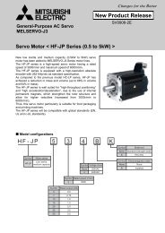
This users manual describes the specifications, handling and programming method for the AJ65BT-<br />
D75P2-S3 positioning module (hereinafter referred to as the D75P2), which can be used as an<br />
intelligent device station for the CC-Link system.<br />
An overview of the D75P2’s positioning control is shown in Figure 1.1.<br />
Master module<br />
Communication<br />
D75P2<br />
Set data<br />
Forward<br />
pulse<br />
Error value<br />
Drive module<br />
D/A<br />
Speed<br />
command<br />
Servo<br />
Servo motor<br />
M<br />
Reverse<br />
pulse<br />
Counter<br />
Converter<br />
Amplifier<br />
Interface<br />
PG<br />
Feedback pulse<br />
· A7PHP<br />
· A7HGP<br />
· PC9800<br />
series<br />
· DOS/V<br />
personal<br />
computer<br />
· AD75TU<br />
Speed (V)<br />
Pulse standing amount<br />
Pulse distribution<br />
Servo motor speed<br />
Time (t)<br />
Fig. 1.1 Overview of positioning control<br />
1-1
1. Overview MELSEC-A<br />
1.1 Features<br />
The features of the D75P2 are listed below.<br />
(1) Compatible with distributed systems<br />
The D75P2 can be placed near a distributedly allocated servo amplifier or stepping motor.<br />
(2) Easily adaptable to an absolute-position detection system<br />
(a) By connecting a servo system that supports absolute positions, the D75P2 can be used with<br />
an absolute-position detection system.<br />
(b) Once the location of the home position has been determined, the D75P2 can return to the<br />
address prior to power-up using the absolute-position restoration function.<br />
(c) With the absolute-position detection system, the location of the home position can be<br />
determined by means of the data-set-type home position return.<br />
Therefore, wiring to items such as a near-point dog is required.<br />
(3) Control via mechanical system input is possible<br />
With external inputs such as external start, stop and speed/position switch, the positioning control<br />
can be performed without using a sequence program.<br />
(4) Various positioning control functions are available<br />
(a) Various functions required of a positioning system are included, such as positioning control<br />
to any position, fixed-dimension feed control and uniform speed control.<br />
An overview of positioning control functions is provided in Section 1.4.<br />
• A maximum of 600 data items per axis can be set for positioning data, including the<br />
positioning address, control method, operation pattern, etc..<br />
• Linear control (two-axis simultaneous execution is allowed) can be performed for the<br />
positioning of each axis: independent positioning using one positioning data item, or<br />
continuous positioning via the continuous execution of multiple data items.<br />
• Linear interpolation control with two axes, as well as circular interpolation control, can be<br />
done for the positioning of multiple axes: independent positioning using one positioning<br />
data item, or continuous positioning via the continuous execution of multiple data items.<br />
(b) The control methods specified by positioning data include the position control, speed control<br />
and speed/position switch control.<br />
(c) Depending upon the operation pattern set by the user using positioning data, continuous<br />
positioning can be performed for multiple axes or each axis using multiple positioning data<br />
items.<br />
Continuous positioning can also be performed for multiple blocks, each of which consisting<br />
of multiple positioning data items.<br />
(d) The home position return control has been extended.<br />
• Seven types of home position return methods are available: the near-point dog method<br />
(one type), stopper stop method (three types), count method (two types) and data-set<br />
method (one type).<br />
(However, the data-set method is available only when using an absolute-position<br />
system.)<br />
• The home position return retry function is now available in order to realize positioning<br />
control from any position relative to the home position of a machine.<br />
(e) Two acceleration/deceleration methods are available: the automatic trapezoid<br />
acceleration/deceleration and S-curve acceleration/deceleration. The user can select from<br />
the automatic trapezoid acceleration/deceleration or S-curve acceleration/deceleration.<br />
1-2
1. Overview MELSEC-A<br />
(5) Faster pulse output and longer distance to the drive module<br />
(a) The D75P2 is equipped with pulse-output interfaces for a differential driver and an open<br />
collector.<br />
(b) By connecting to the differential driver, higher speed and longer distance can be achieved.<br />
• When connecting to a differential driver<br />
• When connecting to an open collector<br />
: 400 kpps, 10 m (32.8 ft.) maximum.<br />
: 200 kpps, 2 m (6.6 ft.) maximum.<br />
(6) Easy maintenance<br />
The D75P2 has achieved improved maintainability, as in the following:<br />
(a) Various data such as positioning data and parameters are stored internally in the flash<br />
memory of the D75P2.<br />
Therefore, data can be retained without a battery.<br />
(b) Error display and the status of mechanical system input and zero input can be checked on<br />
the 17-segment monitor.<br />
(c)<br />
Errors are subdivided in order to improve first-time diagnostics.<br />
(d) Confirmation of the contents of errors and warnings is done easier than the way it has been<br />
conventionally done, since 16 items each of history data, such as errors and warnings, can<br />
be retained.<br />
1-3
1. Overview MELSEC-A<br />
1.2 Purpose of Positioning<br />
The positioning refers to moving a movable object (processed materials, tools, etc.) at a fixed speed<br />
and stopping it accurately at the intended position.<br />
Typical usage examples are shown below.<br />
(1) Fixed-dimension feed<br />
Feed a sheet for a fixed dimension<br />
and cut it.<br />
Cut<br />
M<br />
Feed motor<br />
Fig. 1.2 Fixed-dimension feed<br />
(2) Tapping<br />
To perform thread chasing to a<br />
fixed depth for processed material,<br />
repeat the following steps:<br />
1) Fast forward<br />
2) Process feed (thread chasing)<br />
3) Fast rewind<br />
Thread chasing motor<br />
M<br />
Fast forward<br />
Work<br />
Process feed<br />
Fast rewind<br />
Fig. 1.3 Tapping<br />
(3) Steel-plate drilling (X-Y table movement)<br />
Drill a hole at the fixed position<br />
using two motors (one motor each<br />
for vertical and horizontal).<br />
Y2<br />
Y3<br />
Y4<br />
No.1<br />
No.2<br />
No.3<br />
No.4<br />
Vertical feed motor<br />
Y1<br />
X1 X2 X3 X4<br />
Zero<br />
Horizontal feed motor<br />
Fig. 1.4 Steel plate drilling<br />
1-4
1. Overview MELSEC-A<br />
1.3 Types of Positioning<br />
Each of the two axes can be used independently for positioning, or the two axes can be used for the<br />
positioning of orthogonal axes.<br />
The following methods as shown in the figures are available when positioning from address number 1<br />
to number 2.<br />
(1) Individual operation<br />
This is a method by which each of the vertical and horizontal directions is positioned individually.<br />
First, positioning is performed in the horizontal direction X, then in the vertical direction Y.<br />
No.2<br />
Y<br />
No.1<br />
X<br />
(2) Simultaneous operation<br />
This is a method that designates one of the two motors to perform positioning in the X direction<br />
and the other in the Y direction, driving them simultaneously to reach the intended position.<br />
Since each of the acceleration/deceleration time, speed and travel distances for the two motors is<br />
independent, this operation moves along a curve.<br />
No.2<br />
Y<br />
No.1<br />
X<br />
(3) Linear interpolation operation<br />
This is a method that operates two motors simultaneously to move along a straight diagonal line.<br />
To move along a straight line, calculation is performed via the positioning module equipped with<br />
an interpolation function, and the resultant pulse is distributed to the two motors for control,<br />
because the acceleration/deceleration times and speeds of the two motors generally vary.<br />
No.2<br />
Y<br />
No.1<br />
X<br />
1-5
1. Overview MELSEC-A<br />
(4) Circular interpolation operation<br />
This is a method that operates two motors simultaneously to execute the interpolation operation<br />
for the circular locus.<br />
To move along a circular line, calculation is performed for the positioning module equipped with a<br />
circular interpolation function that controls the acceleration/deceleration times and speeds of the<br />
two motors, and the resultant pulse is distributed to the two motors for control.<br />
Auxiliary<br />
point<br />
No.2<br />
Y<br />
No.1<br />
Y<br />
No.1<br />
Center point<br />
No.2<br />
Circular interpolation by specifying<br />
an auxiliary point<br />
X<br />
X<br />
Circular interpolation by specifying<br />
the center point<br />
1-6
1. Overview MELSEC-A<br />
1.4 Overview of Positioning Control<br />
This section describes the data that needs to be set for positioning, along with the types of positioning<br />
controls and operation patterns available.<br />
1.4.1 Data setting required for positioning control<br />
In order to perform positioning using the D75P2, several data items listed below must be set.<br />
Data for which setting is required<br />
Parameters for positioning Basic parameter 1<br />
Basic parameter 2<br />
Extended parameter 1<br />
Extended parameter 2<br />
These are set according to the system configuration and<br />
mechanical equipment.<br />
Parameters for<br />
home position return<br />
Basic parameter<br />
Extended parameter<br />
Data for positioning<br />
Positioning data<br />
This sets how to control and operate a machine.<br />
Positioning start<br />
information<br />
This is set when a special start such as block start,<br />
simultaneous start, repeated start or start by condition<br />
testing is performed.<br />
Positioning start data<br />
This sets which positioning data to start with,<br />
and whether to end or continue positioning<br />
for the next block.<br />
Special start data<br />
This sets the start type.<br />
Condition data<br />
This sets the conditions for special positioning.<br />
1-7
1. Overview MELSEC-A<br />
1.4.2 Positioning control methods<br />
The following positioning functions are available for the D75P2, and they are controlled by control<br />
methods *1 of 1) through 8). Use positioning data to set the control method.<br />
* 1) to 6): Control of “positioning” locus and operation<br />
7) to 8): Control of “positioning” data<br />
Linear positioning function<br />
1) Linear control of single-axis<br />
This performs positioning along a straight locus from<br />
2) Linear interpolation control .................. the current stop position toward the specified position.<br />
of dual-axes<br />
Fixed-dimension feed-positioning function<br />
3) Fixed-dimension feed control .................. This performs positioning for the specified travel along<br />
a straight locus from the current stop position.<br />
Circular positioning function<br />
4) Circular interpolation control .................... This performs positioning along a circular locus from<br />
the current stop position towards the specified position.<br />
Speed-control positioning function<br />
5) Speed control .......................................... This moves at the specified speed from the current stop<br />
position toward the specified position.<br />
(The operation continues until a stop command is<br />
input.)<br />
Speed/position switch positioning function<br />
6) Speed/position switch control .................. This moves at the specified speed from the current stop<br />
position toward the specified position, and performs<br />
positioning for the specified travel from the moment a<br />
speed/position switch signal is input.<br />
Present-value change function<br />
7) Present value change .............................. This changes the present feed value to the specified<br />
value.<br />
JUMP function<br />
8) JUMP instruction ...................................... This jumps the control point to the specified positioning<br />
data number while in the continuous locus control<br />
(operation pattern: 02). (Specification of unconditional<br />
or execution condition is made.)<br />
*1: See Section 6.1 for details on control methods.<br />
1-8
1. Overview MELSEC-A<br />
1.4.3 Specification of positioning address<br />
For positioning control, there are two methods used to designate a position.<br />
(1) Absolute method<br />
This method performs positioning by specifying the position relative to home position (absolute<br />
address). This address is used as the positioning address (the starting point can be positioned at<br />
any location).<br />
Address<br />
Address<br />
100<br />
100 Address<br />
150 Address<br />
300<br />
Address 150<br />
Address 100<br />
Address 150<br />
• Starting point<br />
Endpoint<br />
Home position<br />
(reference point)<br />
100<br />
Point A<br />
150<br />
Point B<br />
300<br />
Point C<br />
Within the stroke limit range<br />
Fig. 1.5 Positioning by absolute method<br />
(2) Increment method<br />
This method performs positioning by specifying the direction and increment of travel using the<br />
currently stopped position as the starting point.<br />
Travel increment<br />
+100<br />
Travel increment +100<br />
Travel increment<br />
+100<br />
Travel increment<br />
-100<br />
Travel increment -150<br />
Travel increment -100 Travel increment +50<br />
• Starting point<br />
Endpoint<br />
Home position<br />
(reference point)<br />
100<br />
Point A<br />
150<br />
Point B<br />
300<br />
Point C<br />
Within the stroke limit range<br />
Fig. 1.6 Positioning by increment method<br />
1-9
1. Overview MELSEC-A<br />
1.4.4 Operation pattern<br />
The following types of operation patterns are available.<br />
• Individual positioning Individual positioning control (operation pattern: 00)<br />
(ends positioning)<br />
• Continuous positioning Continuous positioning control (operation pattern: 01)<br />
(continues positioning)<br />
Continuous locus control (operation pattern: 11)<br />
(1) Individual positioning control (operation pattern = 00: ends positioning)<br />
The operation is completed with positioning for the specified positioning data alone. The<br />
positioning completion of this operation pattern is also used as the operation pattern for the last<br />
positioning data of continuous positioning and continuous-locus positioning.<br />
(2) Continuous positioning control (operation pattern = 01: continues positioning)<br />
The operation stops temporarily upon the completion of positioning for the specified positioning<br />
data, then continues with the next positioning data number.<br />
This is specified when performing positioning in which the direction changes because of multiple<br />
positioning data items having consecutive positioning data numbers.<br />
(3) Continuous locus control (operation pattern = 11: continues positioning)<br />
After executing positioning using the specified positioning data, the operation changes its speed<br />
to that of the next positioning data number and continues positioning.<br />
This is specified when continuously executing multiple positioning data items having consecutive<br />
positioning data numbers at a specified speed.<br />
1-10
1. Overview MELSEC-A<br />
1.4.5 Block positioning control<br />
Block positioning is a control that continuously executes the positioning of specified blocks. One block<br />
is equivalent to a series of positioning data up to the completion of positioning (operation pattern = 00)<br />
by individual or continuous positioning control.<br />
A maximum of 50 blocks per axis can be specified.<br />
Using a one-time start command from the PC CPU or external, complex positioning control can be<br />
performed.<br />
The block positioning control can be performed by specifying the positioning start number and<br />
positioning start information in the buffer memory.<br />
Speed<br />
Positioning continued (01)<br />
Dwell time<br />
Positioning completed (00)<br />
Positioning<br />
Address (+) direction<br />
completed (00)<br />
Positioning completed (00)<br />
Time<br />
Positioning continued (11)<br />
Address (-) direction<br />
Positioning continued (11)<br />
Speed<br />
One block<br />
One block<br />
One block<br />
ON<br />
OFF<br />
Positioning start<br />
ON<br />
OFF<br />
Start completed<br />
ON<br />
OFF<br />
BUSY<br />
Positioning completed OFF ON<br />
1-11
1. Overview MELSEC-A<br />
1.4.6 Overview of acceleration/deceleration processing<br />
Acceleration/deceleration processing for the positioning operation, manual pulse-generator operation,<br />
home position return operation and JOG operation is performed using the user-specified method,<br />
acceleration time and deceleration time.<br />
(1) Acceleration/deceleration method<br />
There are two types of acceleration and deceleration processing: the automatic trapezoid<br />
acceleration/deceleration method and the S-curve acceleration/deceleration method. An<br />
extended parameter is used to set which method is used.<br />
The specified acceleration/deceleration method is applied to all accelerations and decelerations<br />
when starting and completing the positioning operation, home position return operation and JOG<br />
operation, as well as when changing the speed.<br />
1) Automatic trapezoid acceleration/deceleration method<br />
This method accelerates and decelerates in a linear fashion based on the speed limit value<br />
and user-specified acceleration time/deceleration time.<br />
Speed<br />
Distance<br />
2) S-curve acceleration/deceleration method<br />
This method reduces the load on the motor when starting and stopping.<br />
This method gradually accelerates or decelerates based on the user-specified acceleration<br />
time and deceleration time, S-curve ratio (1 % to 100 %) and speed limit value.<br />
Speed<br />
Distance<br />
(2) Acceleration time, deceleration time, rapid-stop deceleration time<br />
(a) Four types each of the acceleration time and deceleration time for positioning control can be<br />
set using basic parameter 2 and extended parameter 2.<br />
Also, the acceleration time and deceleration time can be selected from 1 to 65535 ms or 1 to<br />
8388608 ms using the acceleration/deceleration time setting size selection in extended<br />
parameter 1.<br />
• Acceleration time ..... The time elapses before the speed of 0 reaches the limit value.<br />
• Deceleration time ..... The time elapses before the speed at the limit value reaches 0.<br />
(b) The rapid-stop deceleration time (1 to 65535 ms or 1 to 8388608 ms) is set using the<br />
acceleration/deceleration time setting size selection of extended parameter 1.<br />
Remark<br />
The selection of 1 to 65535 ms or 1 to 8388608 ms for the acceleration time, deceleration time and<br />
rapid-stop deceleration time is set for each axis.<br />
1-12
1. Overview MELSEC-A<br />
1.4.7 Overview of start<br />
With the positioning control, operation is started in the following flow after the necessary parameters<br />
and data have been set.<br />
Setting the start number<br />
• Set a start number.<br />
A start number can be set within the range of 1 to 600, 7000 to 7010, 9001 to 9003, 9900 and 9901.<br />
The start contents at the time the start signal is turned on are determined by the set number.<br />
Start<br />
For single-axis: RY(n+1)0 is turned on.<br />
For dual-axis: RY(n+1)1 is turned on.<br />
Start number: 9900<br />
Absolute position restoration<br />
Start number: 9901<br />
Present value change<br />
Start number: 9901<br />
Mechanical home position return start<br />
Start number: 9902<br />
High-speed home position return start<br />
Start number: 9903<br />
High-speed mechanical home position return<br />
Start number: 7000 to 7010<br />
Block positioning<br />
Start number: 1 to 600<br />
Positioning numbers 1 to 600<br />
1-13
1. Overview MELSEC-A<br />
1.4.8 Overview of restart<br />
If the operation stops due to the generation of a stop factor during the positioning operation, the<br />
positioning of stopped positioning data can be performed to the endpoint using the restart command.<br />
(1) When the remote I/O generates a restart command<br />
1) If the axis operation is in the stop state, positioning from the stopped position to the end of<br />
the stopped positioning data is performed regardless of the absolute method or increment<br />
method used.<br />
2) If the axis operation is in other than the stop state, a restart disabled warning (warning code<br />
104) occurs and the restart command is ignored.<br />
[For the increment method]<br />
When the travel increment along axis 1 is 600 and that along axis 2 is 300<br />
Axis 2<br />
Axis 2<br />
400<br />
200<br />
100<br />
Stop position by a stop factor<br />
Starting<br />
point address<br />
100 300 700<br />
Specified position<br />
Restart<br />
Axis 1<br />
400<br />
200<br />
Stop position by a stop factor<br />
300 700<br />
Stop position<br />
after restart<br />
Operation upon<br />
restart<br />
Axis 1<br />
(2) When the positioning start signal or external start signal is turned on<br />
If the axis operation is in standby or the stop state, positioning is performed from the head of the<br />
positioning start data regardless of the absolute method or increment method used (as with<br />
normal positioning).<br />
[For the increment method]<br />
When the travel increment along axis 1 is 600 and that along axis 2 is 300<br />
400<br />
200<br />
100<br />
Axis 2<br />
Stop position by a stop factor 500<br />
Starting<br />
point address<br />
100 300 700<br />
Specified position<br />
Positioning start<br />
Axis 1<br />
200<br />
Axis 2<br />
Stop position by a stop factor<br />
Starting point address<br />
300 900<br />
Stop position<br />
after start<br />
Operation<br />
when starting<br />
positioning<br />
Axis 1<br />
1-14
1. Overview MELSEC-A<br />
1.4.9 Overview of home position return<br />
The home position return is to confirm mechanical home position at power-on or other times.<br />
The following seven types of home position returns are available.<br />
(1) Near-point dog type (one type)<br />
This type stops by a zero signal after the near-point dog switches from on to off.<br />
(2) Stopper type (three types)<br />
(a) Stopper (1) (due to the elapse of the dwell timer)<br />
The home position return of this type completes when the dwell time has elapsed after being<br />
decelerated by the near-point dog switching on and stopped by a stopper.<br />
(b) Stopper (2) (due to a zero signal when coming in contact with a stopper)<br />
The home position return of this type is completed by a zero signal after decelerated by<br />
near-point dog on and stopped by a stopper.<br />
(c) Stopper (3) (no near-point dog method)<br />
The home position return of this type is completed by a zero signal after it has moved at the<br />
creep speed and stopped by a stopper.<br />
(3) Count type (two types)<br />
(a) Count type (1) (using the zero signal)<br />
The home position return of this type is stopped by the zero signal once after moving for the<br />
specified travel increment once the near-point dog has been turned on.<br />
(b) Count type (2) (without using the zero signal)<br />
The home position return of this type is stopped by moving for the specified increment of<br />
travel after the near-point dog has been turned on.<br />
[Near-point dog type]<br />
Speed<br />
Current position<br />
[Stopper type (1)]<br />
Speed<br />
Time<br />
Stopper<br />
[Count type (1)]<br />
Speed<br />
Travel increment<br />
Time<br />
Time<br />
Home position return<br />
start signal<br />
Near-point dog signal<br />
Zero signal<br />
1-15
1. Overview MELSEC-A<br />
(4) Data-set type (one type)<br />
The home position return of this type sets the home position address to the present value during<br />
the home position return execution.<br />
This can be used for the absolute-position system.<br />
Remark<br />
1) Home position return can also be performed via the home position return retry function using the<br />
high and low limit switches.<br />
2) After the home position has been determined by the home position return operation, the<br />
positioning operation can be used until the machine’s feed value reaches the home position<br />
address, without using the home position detection signal.<br />
(This equates to positioning to the home position position.)<br />
1-16
1. Overview MELSEC-A<br />
1.5 Overview of Communication<br />
Communication between the D75P2 and a master module uses two types of transmission formats:<br />
cyclic transmission and transient transmission.<br />
An overview of communication using the D75P2 is shown in Figure 1.7.<br />
D75P2<br />
PC CPU<br />
TO instruction (write)<br />
Master station<br />
Cyclic transmission<br />
Remote I/O<br />
Remote register<br />
FROM instruction (read)<br />
Transient transmission<br />
Buffer memory<br />
Fig. 1.7 Overview of communication<br />
1-17
1. Overview MELSEC-A<br />
1.5.1 Cyclic transmission<br />
The following explains the cyclic transmission between the D75P2 and master module.<br />
PC CPU Master station D75P2<br />
Buffer memory<br />
FROM<br />
2)<br />
Remote input<br />
(RX)<br />
1)<br />
Link scan<br />
Remote input<br />
(RX)<br />
TO<br />
3)<br />
Remote output<br />
4)<br />
(RY)<br />
Link scan<br />
Remote output<br />
(RY)<br />
TO<br />
5)<br />
Remote register<br />
6)<br />
(RWw)<br />
Link scan<br />
Remote<br />
register<br />
(RWw)<br />
FROM<br />
8)<br />
Remote register<br />
7)<br />
(RWr)<br />
Link scan<br />
Remote<br />
register<br />
(RWr)<br />
Fig. 1.8 Cyclic transmission<br />
(1) Remote input (RX)<br />
1) The information in the remote input (RX) of the D75P2 is stored in the buffer memory of the<br />
master station during each link scan.<br />
2) The input information stored in the master module is captured by the PC CPU using a FROM<br />
instruction.<br />
(2) Remote output (RY)<br />
3) The information in the remote output (RY) of the D75P2 is written to the buffer memory of<br />
the master station by a TO instruction.<br />
4) The output information stored in the master module is transmitted to the D75P2 during each<br />
link scan.<br />
(3) Remote register (RWw)<br />
5) The information in the remote register (RWw) of the D75P2 is written to the buffer memory of<br />
the master station by a TO instruction.<br />
6) The transmission data information stored in the master module is transmitted to the D75P2<br />
during each link scan.<br />
(4) Remote register (RWr)<br />
7) The information in the remote register (RWr) of the D75P2 is stored in the buffer memory of<br />
the master station during each link scan.<br />
8) The reception data information stored in the master module is captured by the PC CPU<br />
using a FROM instruction during each link scan.<br />
1-18
1. Overview MELSEC-A<br />
1.5.2 Transient transmission<br />
The following explains the transient transmission between the D75P2 and master module.<br />
PC CPU Master station D75P2<br />
Buffer memory<br />
Read/write<br />
1)<br />
2)<br />
Transient<br />
transmission area<br />
3)<br />
Transient transmission<br />
Buffer memory<br />
5) 4)<br />
Transient transmission<br />
Fig. 1.9 Transient transmission<br />
1) Sets data in the send buffer on the master module.<br />
2) Sets an intelligent device station access request signal.<br />
3) The transient data is transmitted from the master module to the D75P2.<br />
4) A response is returned from the D75P2 to the master module.<br />
5) The intelligent device station access complete signal is turned on.<br />
1-19
1. Overview MELSEC-A<br />
1.6 General Procedure before Operation<br />
The following shows the general flowchart for positioning using the D75P2.<br />
Start<br />
Determine the operation plan<br />
Install the AD75P onto a peripheral device<br />
Set parameters and data<br />
Install a module<br />
Connect the module to external devices<br />
Connect the peripheral devices and module<br />
Write the setting data to the D75P2 using the peripheral device<br />
Run a system test<br />
Create a sequence program for positioning<br />
Run an operation test<br />
Make adjustments<br />
Start<br />
operation<br />
· · · Covered in this manual<br />
· · · See the AD75P operating manual<br />
1-20
1. Overview MELSEC-A<br />
1.7 Abbreviations, General Names and Terms Used in this Manual<br />
Abbreviations, general<br />
names, terms<br />
D75P2<br />
CC-Link<br />
Master station<br />
Remote I/O station<br />
Local station<br />
Intelligent device station<br />
Master module<br />
Cyclic transmission<br />
Transient transmission<br />
Peripheral device<br />
Drive module<br />
(Servo amplifier)<br />
Manual pulse generator<br />
Data link system<br />
Network system<br />
AD75P<br />
H/W<br />
I/F<br />
Peripheral device for GPP<br />
S/W<br />
17-segment LED<br />
RX<br />
RY<br />
RWw<br />
RWr<br />
Description<br />
An abbreviation for the AJ65BT-D75P2-S3 positioning module.<br />
An abbreviation for the Control & Communication Link system<br />
The station that controls remote stations, local stations and intelligent device stations<br />
on the CC-Link system.<br />
The remote station that handles bit data only.<br />
(AJ65BTB!-!!, AJ65BTC!-!!)<br />
A station having a CPU and the ability to communicate with the master and other local<br />
stations.<br />
A slave station on the CC-Link system that can perform transient transmission, such<br />
as the D75P2.<br />
The general name for AJ61QBT11, A1SJ61QBT, AJ61BT11 and A1SJ61BT11 when<br />
they are used as master stations.<br />
A transmission method that periodically updates the remote I/O and contents of remote<br />
registers.<br />
A function that updates data with respect to the specified station when an access is<br />
requested from a PC CPU.<br />
The general name for the A7PHP, A7HGP, PC9801 and DOS/V personal computers<br />
that can execute the AD75P given below.<br />
(This is listed separately from the peripheral devices for GPP, as listed below.)<br />
An abbreviation for the pulse-input-compatible drive module (servo amplifier).<br />
An abbreviation for the manual pulse generator (supplied by the user).<br />
An abbreviation for the MELSECNET (II) or MELSECNET/B data link system.<br />
An abbreviation for the MELSECNET/10 network system.<br />
The general name for the software packages SW!RX-AD75P, SW!NX-AD75P and<br />
SW!IVD-AD75P.<br />
(! indicates a numeral greater than 1, which corresponds to the software package<br />
function.)<br />
An abbreviation for hardware.<br />
An abbreviation for interface.<br />
The general name for the A7PHP, A6GPP, PC9801 and DOS/V personal computers<br />
and others to which the software package for the GPP function for creating sequence<br />
programs, etc., is installed.<br />
An abbreviation for software package.<br />
The 17-segment indicator mounted in the upper area of the D75P2.<br />
Remote input<br />
Remote output<br />
Remote register (read area)<br />
Remote register (write area)<br />
1-21
1. Overview MELSEC-A<br />
1.8 Parts Supplied with the Module<br />
When unpacking, check that all of the parts listed below are included. Also, check whether there is<br />
any damage to the parts after unpacking.<br />
Description<br />
Main module (AJ65BT-D75P2) 1<br />
External wiring connector (10136-3000VE) 2<br />
Connector cover (10336-52F0-008) 2<br />
Quantity<br />
1-22
2. System Configuration MELSEC-A<br />
2. System Configuration<br />
This chapter describes the system configuration using the D75P2.<br />
2.1 System Configuration when Using the D75P2<br />
The Figure below shows the system configuration when using the D75P2.<br />
A maximum of 16 D75P2 modules can be connected to a single master station.<br />
CC-Link<br />
Master station<br />
AJ65BT-D75P2-S3<br />
AJ65BT-D75P2-S3<br />
SW IVD-AD75P<br />
A1SD75C01HA<br />
AC30R4<br />
RS-422/RS-232<br />
conversion cable<br />
* See Important (1).<br />
AD75TU<br />
Manual pulse generator<br />
Manual pulse<br />
generator<br />
* See Important (2).<br />
Switch<br />
Switch<br />
Motor<br />
Motor<br />
Servo amplifier<br />
Servo amplifier<br />
Fig. 2.1 System configuration when using the D75P2<br />
Important<br />
(1) The software packages listed below are required in order to use the D75P2.<br />
• For DOS/V personal computer: SW1IVD-AD75P or later<br />
(2) Use software version D or later for the DA75TU.<br />
2-1
2. System Configuration MELSEC-A<br />
2.2 Applicable System<br />
This section describes the CC-Link system master module that can be used with the D75P2 and PC<br />
CPUs that can be used with CC-Link dedicated instructions.<br />
(1) Master modules that can be used with the D75P2<br />
To use the D75P2, use a module with the following symbol (“9707B” and later) inscribed in the<br />
date column of the rated plate.<br />
PROGRAMMABLE CONTROLLER<br />
DATE 9707 B<br />
MITSUBISHI ELECTRIC CORPORATION JAPAN<br />
BD992D013H01<br />
MITSUBISHI<br />
CPU UNIT<br />
MODEL A2USHCPU-S1<br />
MAX 30kSTEP<br />
DATE 9707 B<br />
MITSUBISHI ELECTRIC<br />
BD992D008H38<br />
Manufactured date<br />
Function version<br />
Manufactured date<br />
Function version<br />
(2) PC CPUs that can be used with CC-Link dedicated instructions<br />
The PC CPU models listed below can be used with the CC-Link dedicated instructions:<br />
• A1SHCPU<br />
• A1SJHCPU<br />
• A2SHCPU<br />
• Q2ACPU (function version B or later)<br />
• Q2ACPU-S1 (function version B or later)<br />
• Q3ACPU (function version B or later)<br />
• Q4ACPU (function version B or later)<br />
• Q2ASCPU (function version B or later)<br />
• Q2ASCPU-S1 (function version B or later)<br />
• Q2ASHCPU (function version B or later)<br />
• Q2ASHCPU-S1 (function version B or later)<br />
2-2
2. System Configuration MELSEC-A<br />
2.3 List of Equipment<br />
Table 2.1 lists the products that can be used for a positioning system using the D75P2.<br />
Table 2.1 List of equipment<br />
Product name Model name Contents<br />
Positioning module<br />
AJ65BT-D75P2-S3<br />
Software package for AD75 SW1IVD-AD75P or later Software package for DOS/V personal computer<br />
Plasma handy graphic<br />
A7PHP-SET<br />
• A7PHP main module<br />
programmer<br />
• SW RX-DOS : Basic software package<br />
• SW SRXV-GPPA : GPP function boot floppy disk for A<br />
series<br />
• SW0S-USER : User floppy disk (2HD)<br />
• AC30R4 :<br />
RS-422 cable, 3 m (9.8 ft.) in length<br />
Handy graphic programmer A7HGP-SET • A7PHP main module<br />
• SW HX-DOS : Basic software package<br />
• SW HX-GPPA : GPP function boot floppy disk for A<br />
series<br />
• SW0S-USER : User floppy disk (2HD)<br />
• AC30R4 : RS-422 cable, 3 m (9.8 ft.) in length<br />
• Shoulder strap<br />
Peripheral device for AD75P<br />
PC9800 series<br />
DOS/V personal<br />
computer<br />
(Supplied by the user)<br />
Refer to the AD75P operating manual for details.<br />
Teaching module AD75TU Ver. D or later This sets parameters and positioning data, monitors and<br />
conducts tests for AD75P2.<br />
RS-422 cable AC30R4 Length: 3 m (9.8 ft.) The cable for connecting the<br />
AC100R4 Length: 10 m (32.8 ft.) D75P2 and A7PHP or A7HGP.<br />
AC300R4<br />
Length: 30 m (98.4 ft.)<br />
Conversion cable A1SD75-CO1H Length: 10 cm (3.94 in.) The cable for connecting the<br />
A1SD75-CO1HA AC R4 cable and D75P.<br />
Connection cable (converter) –––––– The RS-232C cable that connects the AD75 and the<br />
PC9801 or DOS/V personal computer, and the<br />
RS232C/RS422 converter (supplied by the user).<br />
Refer to the appendix for details.<br />
Drive module –––––– (Supplied by the user)<br />
Manual pulse generator –––––– (Supplied by the user)<br />
Recommended : MR-HDP01 (manufactured by Mitsubishi<br />
Electric)<br />
Connection<br />
cable *<br />
Absolute-position<br />
detection<br />
function<br />
compatible<br />
Absolute-position<br />
detection<br />
function<br />
noncompatible<br />
AD75C20SH<br />
AD75C20SJ2<br />
AD75C20SJ<br />
AD75C20SC<br />
The cable for the connection between the D75P2 and<br />
servo amplifier (MR-H-A)<br />
The cable for the connection between the D75P2 and<br />
servo amplifier (MR-J2-A)<br />
The cable for the connection between the D75P2 and<br />
servo amplifier (MR-J-A)<br />
The cable for the connection between the D75P2 and<br />
servo amplifier (MR-C-A)<br />
Connection cable –––––– The cable for connecting the D75P2 to the mechanical<br />
system input signal or manual pulse generator (supplied by<br />
the user).<br />
Refer to the manual for details on the connection device.<br />
Remark<br />
* : For the connector cover on the D75P2 side, use the one supplied with the product.<br />
2-3
2. System Configuration MELSEC-A<br />
2.4 Precautions when Using a Stepping Motor<br />
This section describes the precautions when using a stepping motor.<br />
(1) When setting the stepping motor mode<br />
(a) When using a stepping motor with the D75P2, it is necessary to set the stepping motor<br />
mode.<br />
If the stepping motor mode is not set, the stepping motor cannot be controlled normally.<br />
(b) When the stepping motor mode is set, certain restrictions apply to items such as the control<br />
method and positioning address.<br />
Use the module after verifying the restrictions that apply to the stepping motor mode in<br />
Section 7.15.<br />
(2) Use of bias speed at start<br />
While the stepping motor is used, the motor rotation can be started smoothly by selecting the<br />
stepping motor mode and setting the bias speed at start.<br />
(3) The use of S-curve acceleration/deceleration is not allowed<br />
While the stepping motor is used, S-curve acceleration/deceleration cannot be performed.<br />
(4) Circular interpolation control is not allowed<br />
While the stepping motor is used, circular interpolation control cannot be performed.<br />
2-4
3. Specification MELSEC-A<br />
3. Specification<br />
This chapter explains the general specifications, performance specifications and I/O interface with<br />
external devices for the D75P2.<br />
3.1 General Specifications<br />
General specifications for the D75P2 are shown in the table below:<br />
Item<br />
Ambient operating<br />
temperature<br />
0 to 55 °C<br />
Ambient storage temperature –20 to 75 °C<br />
Ambient operating humidity<br />
Ambient storage humidity<br />
10 to 90 %RH, Non-condensing<br />
10 to 90 %RH, Non-condensing<br />
Table 3.1 General specification<br />
Specifications<br />
Vibration resistance Conforming to Frequency Acceleration Amplitude No. of sweeps<br />
JIS B 3501,<br />
IEC 1131-2<br />
Under intermittent<br />
vibration<br />
Under continuous<br />
vibration<br />
10 to 57 Hz<br />
—<br />
0.075 mm<br />
(0.003 in.)<br />
10 times each in<br />
X, Y, Z<br />
57 to 150 Hz 9.8 m/s 2 {1G} — directions<br />
10 to 57 Hz<br />
Shock resistance Conforming to JIS B3501, IEC 1131-2<br />
(147 m/s 2 {15G}, 3 times in each of 3 directions X Y Z)<br />
Operating ambience<br />
No corrosive gases<br />
Operating elevation<br />
2000 m (6562 ft.) max.<br />
Installation location<br />
Control panel<br />
Over voltage category *1 II max.<br />
Pollution level *2<br />
2 max.<br />
—<br />
0.035 mm<br />
(0.001 in.)<br />
57 to 150 Hz 4.9 m/s 2 {0.5G} —<br />
(for 80 min.)<br />
*1: This indicates the section of the power supply to which the equipment is assumed to be<br />
connected between the public electrical power distribution network and the machinery within the<br />
premises. Category II applies to equipment for which electrical power is supplied from fixed<br />
facilities. The surge voltage withstand level for up to the rated voltage of 300 V is 2500 V.<br />
*2: This index indicates the degree to which conductive material is generated in terms of the<br />
environment in which the equipment is used. Pollution level 2 is when only non-conductive<br />
pollution occurs. A temporary conductivity caused by condensation must be expected<br />
occasionally.<br />
3-1
3. Specification MELSEC-A<br />
3.2 Performance Specifications<br />
Performance specifications for the D75P2 are shown in the table below:<br />
3.2.1 Performance specifications<br />
Table 3.2 Performance specifications (1)<br />
Item<br />
Specification<br />
Number of control axes<br />
2 axes<br />
Interpolation function Dual-axis linear interpolation, dual-axis circular interpolation (*1)<br />
Control method<br />
PTP (Point to Point) control, locus control (linear and circular settings possible), speed control,<br />
speed/position switch control<br />
Control unit<br />
mm, inch, degree, pulse<br />
Positioning data<br />
600 data (positioning-data number: 1 to 600)/axis setting possible<br />
Peripheral devices/software DOS/V personal computer/SW1IVD-AD75P or later (*2)<br />
packages<br />
Teaching module<br />
AD75TU (software version D or later)<br />
Backup<br />
Parameters and positioning data are stored in the flash memory (no battery)<br />
Positioning Positioning method PTP control : Increment system/absolute system<br />
Speed/position switch control : Increment system<br />
Locus control<br />
: Increment system/absolute system<br />
Positioning range (*3) Absolute system<br />
• –214748364.8 to 214748364.7 (µm)/–13421772.8 to 13421772.7 (µm)<br />
• –21474.83648 to 21474.83647 (inches)/–1342.17728 to 1342.17727 (inches)<br />
• 0 to 359.99999 (degrees)/0 to 359.99999 (degrees)<br />
• –2147483648 to 2147483647 (pulses)/–134217728 to 134217727 (pulses)<br />
Increment system<br />
• –214748364.8 to 214748364.7 (µm)/–13421772.8 to 13421772.7 (µm)<br />
• –21474.83648 to 21474.83647 (inches)/–1342.17728 to 1342.17727 (inches)<br />
• –21474.83648 to 21474.83647 (degrees)/–1342.17728 to 1342.17727 (degrees)<br />
• –2147483648 to 2147483647 (pulses)/–134217728 to 134217727 (pulses)<br />
Speed/position switch control<br />
• 0 to 214748364.7 (µm)/0 to 13421772.7 (µm)<br />
• 0 to 21474.83647 (inches)/0 to 1342.17727 (inches)<br />
• 0 to 21474.83647 (degrees)/0 to 1342.17727 (degrees)<br />
• 0 to 2147483647 (pulses)/0 to 134217727 (pulses)<br />
Speed command (*3) • 0.01 to 6000000.00 (mm/min.)/0.01 to 375000.00 (mm/min.)<br />
• 0.001 to 600000.000 (inches/min.)/0.001 to 37500.000 (inches/min.)<br />
• 0.001 to 600000.000 (degrees/min.)/0.001 to 37500.000 (degrees/min.)<br />
• 1 to 1000000 (pulse/sec.)/1 to 62500 (pulse/sec.)<br />
Acceleration/deceleration<br />
Automatic trapezoid acceleration/deceleration, automatic S-curve acceleration/deceleration (*4)<br />
processing<br />
Acceleration/deceleration<br />
time<br />
Rapid-stop<br />
deceleration time<br />
Start time<br />
Compensation<br />
Switching between 1 to 65535 (ms) and 1 to 8388608 (ms) is possible<br />
4 patterns of acceleration and deceleration time setting are possible<br />
Switching between 1 to 65535 (ms) and 1 to 8388608 (ms) is possible<br />
(same range as acceleration/deceleration time)<br />
20 ms or less (except link scan time)<br />
Electronic gear or backlash compensation available<br />
Home position return method Near-point dog type (1 type), count types (2 types), stopper types (3 types), data-set type (1 type) (*5)<br />
Absolute-position detection function Compatible with absolute-position detection systems using MR-H and MR-J2<br />
JOG operation function<br />
Available<br />
Manual pulse-generator operation Available<br />
function<br />
M-code output function<br />
Available (either WITH mode or AFTER mode can be selected)<br />
Error display<br />
17-segment display<br />
I/O display<br />
17-segment display and LED display<br />
*1 Circular interpolation cannot be used while the stepping motor is used.<br />
*2 DOS/V is a registered trademark of IBM Japan.<br />
*3 Indicates the setting ranges of the “standard mode/stepping motor mode.”<br />
*4 While the stepping motor is in use, automatic S-curve acceleration/deceleration cannot be used.<br />
*5 Valid only with an absolute-position detection system.<br />
3-2
3. Specification MELSEC-A<br />
Item<br />
Table 3.2 Performance specifications (2)<br />
Specification<br />
CC-Link station type<br />
Intelligent device station<br />
Number of occupied stations 4 stations (128 points each for RX/RY, 16 points each for RWr/RWw)<br />
External power supply (V)<br />
24 DC (20.4 to 26.4 DC)<br />
Applicable conductor size (mm 2 ) 0.75 to 2.00<br />
Module installation screws (mm) M4 × 0.7 × 16 or above<br />
Installation with DIN rail is also possible<br />
Applicable DIN rails<br />
TH35-7.5Fe, TH35-7.5AI, TH35-15Fe (complies with JIS-C2B12)<br />
Applicable solderless terminal RAV1.25 to 3.5, RAV2 to 3.5<br />
24 V DC internal current<br />
0.30<br />
consumption (A)<br />
Noise resistance Noise voltage 500 Vp-p, noise width 1 µs<br />
(based on a noise simulator with noise frequency of 25 to 60 Hz)<br />
Dielectric withstand voltage Power supply/communication system batch - external I/O batch, 500 V AC for 1 minute<br />
Insulation resistance<br />
Power supply/communication system batch - external I/O batch, 10 MΩ or more based on a 500 V DC<br />
insulation resistance tester<br />
External dimensions (mm [in.]) 63.5 (2.5) (H) × 170 (6.7) (W) × 80 (3.1) (D)<br />
Weight (kg [lb.]) 0.50 (1.1)<br />
3-3
3. Specification MELSEC-A<br />
3.2.2 Specifications for I/O interface with external devices<br />
This section explains the I/O interface of the D75P2 with respect to external devices.<br />
(1) Electrical specifications of the D75P2<br />
The table below shows the electrical specifications for D75P2 I/O signals with respect to external<br />
devices:<br />
(a) Input specifications<br />
Signal name<br />
Drive module ready (READY)<br />
In-position signal<br />
Rated input<br />
voltage/current<br />
Range of<br />
voltage used<br />
ON voltage/<br />
current<br />
24 V DC/5 mA 19.2 to 26.4 V DC 17.5 V DC or<br />
more/3.5 mA or<br />
more<br />
Zero signal (PG0) 5 V DC/5 mA 4.5 to 6.1 V DC 2.5 V DC or more/<br />
2 mA or more<br />
24 V DC/7 mA 12 to 26.4 V DC 10 V DC or more/<br />
3 mA or more<br />
OFF voltage/<br />
current<br />
7 V DC or less/<br />
1.7 mA or less<br />
0.5 V DC or less/<br />
0.5 mA or less<br />
3 V DC or less/<br />
0.2 mA or less<br />
Input<br />
resistance<br />
Approx.<br />
4.7 kΩ<br />
Approx.<br />
0.5 kΩ<br />
Approx.<br />
3.5 kΩ<br />
Response<br />
time<br />
4 ms or<br />
less<br />
0.8 ms or<br />
less<br />
0.8 ms or<br />
less<br />
3 µs or less<br />
1 ms or more<br />
3 µs or less<br />
Manual pulse generator phase A<br />
(PULSER A)<br />
5 V DC/5 mA 4.5 to 6.1 V DC 2.5 V DC or more/<br />
3.5 mA or more<br />
1 V DC or less/<br />
1 mA or less<br />
Approx.<br />
1.5 kΩ<br />
1 ms or<br />
less<br />
Manual pulse generator phase B<br />
(PULSER B)<br />
1) Pulse width<br />
2 ms or more<br />
1 ms or<br />
more<br />
1 ms or<br />
more<br />
(Duty ratio 50 %)<br />
2) Phase difference<br />
Phase A<br />
When phase A is ahead of phase B, the<br />
positioning address (present value) increases.<br />
Phase B<br />
0.5 ms or more<br />
Near-point signal (DOG)<br />
Stop signal (STOP)<br />
High limit (FLS)<br />
Low limit (RLS)<br />
External start (STRT)<br />
Speed/position switch signal<br />
(CHG)<br />
24 V DC/5 mA 19.2 to 26.4 V DC 17.5 V DC or<br />
more/3.5 mA or<br />
more<br />
7 V DC or less/<br />
1.7 mA or less<br />
Approx.<br />
4.7 kΩ<br />
4 ms or<br />
less<br />
ABS transmission data ready<br />
complete<br />
ABS data bit 0<br />
ABS data bit 1<br />
24 V DC/5 mA 19.2 to 26.4 V DC 17.5 V DC or<br />
more/3.5 mA or<br />
more<br />
7 V DC or<br />
more/1.7 mA or<br />
more<br />
Approx.<br />
4.7 kΩ<br />
4 ms or<br />
less<br />
3-4
3. Specification MELSEC-A<br />
(b) Output specifications<br />
Signal name<br />
Pulse output<br />
(CW/PULSE/phase A)<br />
Rated load<br />
voltage<br />
Range of load<br />
voltage used<br />
Maximum load<br />
current/<br />
rush current<br />
Maximum<br />
voltage drop<br />
during on<br />
Leak<br />
current<br />
during off<br />
Response<br />
time<br />
• Am26LS31-equivalent differential driver/open collector<br />
• CW/CCW type, PULSE/SIGN type and phase A/B type are selected using the D75P2 and drive module<br />
parameters.<br />
• The relationships between the pulse output mode set by the parameter and the pulse output based on<br />
“positive logic/negative logic selection” are shown below:<br />
Pulse sign Mode Positive logic Negative logic<br />
(CCW/SIGN/phase B) selection Forward rotation Reverse rotation Forward rotation Reverse rotation<br />
CW<br />
CCW<br />
PULSE<br />
SIGN<br />
A φ<br />
B φ<br />
High Low Low High<br />
* In the case of open collector, the rise/fall time and duty ratio are as shown by the figure below.<br />
ON<br />
OFF<br />
tr<br />
tf<br />
5 to 24 V DC 4.75 to 30 V DC 50 mA/one point/<br />
200 mA 10 ms or<br />
less<br />
Error counter clear (CLEAR) 5 to 24 V DC 4.25 to 30 V DC 0.1 A/one point/<br />
0.4 A 10 ms or<br />
less<br />
Servo on<br />
ABS data transmission mode<br />
ABS data request<br />
5 to 24 V DC 4.75 to 30 V DC 0.1 A/one point/<br />
0.4 A 10 ms or<br />
less<br />
0.5 V DC (TYP) 0.1 mA or<br />
less<br />
1 V DC (TYP)<br />
2.5 V DC (MAX)<br />
1 V DC (TYP)<br />
2.5 V DC (MAX)<br />
0.1 mA or<br />
less<br />
0.1 m A or<br />
less<br />
——<br />
2 ms or<br />
less<br />
(resistive<br />
load)<br />
2 ms or<br />
less<br />
(resistive<br />
load)<br />
Pulse rise/fall time (unit tr, tf: µs; duty: %) in the D75P2 ............ when the ambient temperature is normal temperature<br />
Load voltage (V) 26.4 4.75<br />
Cable length (m [ft.]) 1 (3.3) 3 (9.8) 1 (3.3) 3 (9.8)<br />
Load<br />
current<br />
(mA)<br />
Pulse<br />
speed<br />
(kPPS)<br />
tr (rise) tf (fall) Duty tr (rise) tf (fall) Duty tr (rise) tf (fall) Duty tr (rise) tf (fall) Duty<br />
2 200 0.04 1.70 30 0.06 2.04 27 0.04 0.63 43 0.04 1.08 38<br />
100 0.08 3.00 33 0.07 3.49 29 0.06 0.64 47 0.04 1.28 42<br />
10 0.07 3.20 48 0.08 6.80 46 0.04 0.64 49 0.06 1.30 49<br />
5 200 0.06 1.10 39 0.07 1.83 33 0.04 0.26 48 0.04 0.92 46<br />
100 0.07 1.24 43 0.08 2.50 36 0.05 0.26 48 0.06 0.44 47<br />
10 0.07 1.20 49 0.08 2.70 49 0.05 0.30 50 0.06 0.44 50<br />
20 200 0.07 0.42 46 0.08 0.72 43 0.06 0.22 47 0.06 0.22 49<br />
100 0.07 0.40 48 0.11 0.74 47 0.08 0.24 50 0.06 0.24 50<br />
10 0.07 0.40 50 0.08 0.79 50 0.06 0.24 50 0.06 0.24 50<br />
50 200 0.08 0.28 48 0.09 0.37 47 0.08 0.20 47 0.10 0.18 50<br />
100 0.08 0.27 48 0.13 0.37 48 0.08 0.22 49 0.12 0.20 51<br />
10 0.09 0.27 50 0.09 0.37 50 0.08 0.22 50 0.12 0.20 50<br />
3-5
3. Specification MELSEC-A<br />
(2) Specifications for I/O interface with external devices<br />
Specifications for I/O interface of the D75P2 with respect to external devices are shown in the<br />
table below:<br />
(a) Layout of connector signals<br />
The signal layout of the connector for connecting external devices to the D75P2 (for one<br />
axis) is shown below:<br />
(Axis 1 and 2 use the same signal layout for connecting external devices.)<br />
Pin layout<br />
Pin<br />
No.<br />
Signal name *<br />
Signal direction<br />
AD75 - external<br />
Connection destination<br />
36<br />
19<br />
18<br />
1<br />
36<br />
35<br />
34<br />
33<br />
32<br />
31<br />
30<br />
29<br />
28<br />
27<br />
26<br />
25<br />
24<br />
23<br />
22<br />
21<br />
20<br />
19<br />
18<br />
17<br />
16<br />
15<br />
14<br />
13<br />
12<br />
11<br />
10<br />
9<br />
8<br />
7<br />
6<br />
5<br />
4<br />
3<br />
2<br />
1<br />
Common<br />
1)<br />
Common<br />
ABS transmission data ready complete 18)<br />
Common (ABS IN) 19)<br />
Common (ABS OUT) 20)<br />
ABS request 21)<br />
ABS transfer mode 22)<br />
Servo on 23)<br />
Manual pulse generator<br />
2)<br />
Manual pulse generator<br />
Common 3)<br />
Zero signal common 5)<br />
Zero signal (+5 V) 6)<br />
Error counter clear common 4)<br />
Pulse sign (differential –)<br />
7)<br />
Pulse output (differential –)<br />
Pulse sign common<br />
(Open collector)<br />
8)<br />
Pulse output common<br />
(Open collector)<br />
ABS data bit 1<br />
24)<br />
ABS data bit 0<br />
External start 9)<br />
Speed/position switch signal 10)<br />
Stop signal 11)<br />
Low limit 12)<br />
High limit 13)<br />
Near-point signal 14)<br />
Manual pulse generator<br />
2)<br />
Manual pulse generator<br />
In-position 15)<br />
Drive module ready 16)<br />
Zero signal (+24 V) 6)<br />
Error counter clear 17)<br />
Pulse sign (differential +)<br />
7)<br />
Pulse output (differential +)<br />
Pulse sign (open collector)<br />
8)<br />
Pulse output (open collector)<br />
COM<br />
COM<br />
TLC<br />
COM<br />
COM<br />
ABSR<br />
ABSM<br />
SON<br />
PULSER B–<br />
PULSER A–<br />
COM<br />
PG0 COM<br />
PG0 (5 V)<br />
CLEAR COM<br />
PULSE R–<br />
PULSE F–<br />
PULSE COM<br />
PULSE COM<br />
ZSP<br />
D01<br />
STRT<br />
CHG<br />
STOP<br />
RLS<br />
FLS<br />
DOG<br />
PULSE B+<br />
PULSE A+<br />
INPS<br />
READY<br />
PG0 (24 V)<br />
CLEAR<br />
pulse R+<br />
pulse F+<br />
PULSE R<br />
PULSE F<br />
↔<br />
↔<br />
←<br />
—<br />
—<br />
←<br />
←<br />
→<br />
←<br />
←<br />
↔<br />
←<br />
←<br />
↔<br />
→<br />
→<br />
↔<br />
↔<br />
→<br />
→<br />
←<br />
←<br />
←<br />
←<br />
←<br />
←<br />
←<br />
←<br />
←<br />
←<br />
←<br />
→<br />
→<br />
→<br />
→<br />
→<br />
(External device)<br />
(External device)<br />
Drive module<br />
Drive module<br />
Drive module<br />
Drive module<br />
Drive module<br />
Drive module<br />
Manual pulse generator<br />
Manual pulse generator<br />
Drive module<br />
Drive module<br />
Drive module<br />
Drive module<br />
Drive module<br />
Drive module<br />
Drive module<br />
Drive module<br />
Drive module<br />
Drive module<br />
(External device)<br />
(External device)<br />
(External device)<br />
Limit switch<br />
Limit switch<br />
Near-point dog<br />
Manual pulse generator<br />
Manual pulse generator<br />
Drive module<br />
Drive module<br />
Drive module<br />
Drive module<br />
Drive module<br />
Drive module<br />
Drive module<br />
Drive module<br />
* 1) to 24) beside signal names are numbers corresponding to the explanations in “(b) Description of<br />
connector signals.”<br />
3-6
3. Specification MELSEC-A<br />
(b) Description of connector signals<br />
The description of each signal for the connector for connecting external devices to the<br />
D75P2 (for one axis) is explained below:<br />
1) Common --- (Pin numbers 36, 35)<br />
• A common for the near-point signal, high/low limit, stop signal, control switch signal,<br />
and external start.<br />
2) Manual pulse generator (phase B –), manual pulse generator (phase A –)<br />
--- (Pin numbers 28, 27)<br />
Manual pulse generator (phase B +), manual pulse generator (phase A +)<br />
--- (Pin numbers 10, 9)<br />
• Inputs the phase A/B pulse signal of the manual pulse generator and rotary<br />
encoder.<br />
• When phase A is ahead of phase B, the positioning address increases.<br />
• When phase B is ahead of phase A, the positioning address decreases.<br />
[when increasing]<br />
[when decreasing]<br />
Phase A<br />
Phase A<br />
Phase B<br />
Phase B<br />
Positioning<br />
Positioning<br />
address +1 +2<br />
..........<br />
address –1 –2<br />
..........<br />
3) Common --- (Pin number 26)<br />
• A common for the drive module ready and in-position.<br />
4) Error counter clear common --- (Pin number 23)<br />
• A common for the error counter clear.<br />
5) Zero signal common --- (Pin number 25)<br />
• A common for the zero signal (+5 V) and zero signal (+24 V).<br />
6) Zero signal (+5 V), zero signal (+24 V) --- (Pin numbers 24, 6)<br />
• Inputs the home position signal at the time of home position return.<br />
Generally, the home position grid signal of a pulse encoder is used.<br />
• This signal is also used when the home position return method is “stopper stop” and<br />
the home position return complete is input externally.<br />
• The zero point is detected at fall.<br />
7) Pulse sign, pulse output (differential –) --- (Pin numbers 22, 21)<br />
Pulse sign, pulse output (differential +) --- (Pin numbers 4, 3)<br />
• The pulse and pulse sign for positioning are output to the drive module that<br />
corresponds to the differential driver.<br />
8) Pulse sign common, pulse output common (open collector) --- (Pin numbers 20, 19)<br />
Pulse sign, pulse output (open collector) --- (Pin numbers 2, 1)<br />
• The pulse and pulse sign for positioning are output to the drive module that<br />
corresponds to the open collector.<br />
9) External start --- (Pin number 16)<br />
• Used as an input signal for external positioning start, speed change request or skip<br />
request.<br />
• The selection of external start function in extended parameter 2 determines in which<br />
function the external start is used.<br />
3-7
3. Specification MELSEC-A<br />
10) Speed/position switch signal --- (Pin number 15)<br />
• Input control switch signals during speed/position switch control.<br />
11) Stop signal --- (Pin number 14)<br />
• Input when positioning is stopped.<br />
• When this signal turns on, the D75P2 stops the positioning currently executed and<br />
turns off the start signal.<br />
After that, the D75P2 will not start operating even if this signal is switched from on<br />
to off.<br />
12) Low limit --- (Pin number 13)<br />
• Input from the limit switch provided at the low limit of stroke.<br />
• When this signal turns off, positioning stops.<br />
• Become the low limit of search for the near-point signal when automatic home<br />
position return is enabled.<br />
13) High limit --- (Pin number 12)<br />
• Input from the limit switch provided at the high limit of stroke.<br />
• When this signal turns off, positioning stops.<br />
• Become the high limit of search for the near-point signal when automatic home<br />
position return is enabled.<br />
14) Near-point signal --- (Pin number 11)<br />
• Used for near-point dog detection during home position return.<br />
• Detects the change in near-point dog from off → on at rise.<br />
• Detects the change in near-point dog from on → off at fall.<br />
15) In-position --- (Pin number 8)<br />
• The in-position signal from the drive module is input.<br />
16) Drive module ready --- (Pin number 7)<br />
• Turn on when the drive module is normal and is in a feed-pulse acknowledge<br />
enable state.<br />
• The D75P2 checks the drive module ready signal and outputs a home position<br />
return request if it is not in a ready status.<br />
• This signal is turned off when the drive module becomes malfunction, for example,<br />
when an error occurs in the control power supply of the drive module.<br />
• If this signal is turned off during positioning, positioning stops. Operation does not<br />
start even if the signal is turned on again.<br />
• When this signal turns off, the home position return complete signal also turns off.<br />
3-8
3. Specification MELSEC-A<br />
17) Error counter clear --- (Pin number 5)<br />
• Turns on after pulse output stops when home position return is performed using the<br />
stopper stop method 1) or 2).<br />
(Example) Home position return using the stopper stop method 2)<br />
Speed<br />
Home position return speed<br />
Stopper<br />
Creep speed<br />
Time<br />
Near-point dog<br />
Zero detection signal<br />
10 ms<br />
CLEAR<br />
After feed-pulse output stops<br />
• The error counter clear is output for approximately 10 ms.<br />
• As for the drive module, use one that can reset the standing pulse amount for the<br />
internal error counter when the D75P2 turns this signal on.<br />
18) ABS transmission data ready complete --- (Pin number 34)<br />
• This signal indicates that preparation of transmission data is complete during the<br />
ABS transfer mode.<br />
19) Common (ABS IN) --- (Pin number 33)<br />
• A common for the ABS data bit 0, ABS data bit 1 and ABS transmission data ready<br />
complete.<br />
20) Common (ABS OUT) --- (Pin number 32)<br />
• A common for the servo ON, ABS transfer mode and ABS request.<br />
21) ABS request --- (Pin number 31)<br />
• This is the signal for requesting ABS data in the ABS transfer mode.<br />
22) ABS transfer mode --- (Pin number 30)<br />
• Changes the mode to ABS transfer.<br />
• While this is on, the “ABS data bit 0 [D01],” “ABS data bit 1 [ZSP]” and “ABS<br />
transmission data ready complete [TLC]” signals become valid.<br />
23) Servo ON --- (Pin number 29)<br />
• This signal turns on power to the servo base circuit and changes the status to<br />
operation enable.<br />
24) ABS data bit 0, bit 1 --- (Pin numbers 17, 18)<br />
• ABS data transferred to the D75P2 from the servo during the ABS operation mode.<br />
bit 0 indicates the lower bit, while bit 1 indicates the upper bit.<br />
3-9
3. Specification MELSEC-A<br />
(c)<br />
Internal circuits<br />
The internal circuits of interface for connecting external devices to the D75P2 are shown by<br />
the schematic diagrams below:<br />
! : Wiring required, : Wire as necessary<br />
I/O<br />
classification<br />
External wiring Pin No. Internal circuit Signal name Description on/off status Wiring<br />
Input 11 Near-point<br />
signal<br />
DOG<br />
• The signal for near-point detection<br />
during home position return.<br />
External<br />
wiring<br />
D75P2<br />
OFF<br />
required/<br />
not<br />
required<br />
When the high<br />
limit switch<br />
is not used<br />
When the low<br />
limit switch<br />
is not used<br />
12 High limit LS FLS • The signal for the limit switch<br />
provided at the high limit of stroke.<br />
• Also used in the home position<br />
return retry function.<br />
13 Low limit LS RLS • The signal for the limit switch<br />
provided at the low limit of stroke.<br />
• Also used in the home position<br />
return retry function.<br />
14 Stop signal STOP • The signal to stop positioning<br />
externally.<br />
• When stopping positioning, turn<br />
this signal on for 4 ms or longer.<br />
• Once this signal is turned on,<br />
switching it back to off does not<br />
resume operation.<br />
ON<br />
ON !<br />
OFF<br />
(stop)<br />
ON !<br />
OFF<br />
(stop)<br />
ON<br />
OFF<br />
(stop)<br />
15 Speed/ CHG • The signal that switches speed<br />
OFF<br />
position<br />
control to position control during<br />
speed/position switch control.<br />
switch signal<br />
ON<br />
5-12 V<br />
A<br />
B<br />
0 V<br />
Manual pulse<br />
generator<br />
(MR-HDP01)<br />
For MR-J2-"A<br />
RD<br />
INP<br />
VDD<br />
COM<br />
LZ<br />
LZR<br />
16 External start STRT • The signal that executes external<br />
positioning start, speed change<br />
and SKIP request.<br />
• To make external start valid, turn<br />
this signal on for 4 ms or longer.<br />
• Set which function to use via an<br />
extended parameter.<br />
35 Common COM • Input voltage 24 V DC. —— !<br />
36<br />
(+)<br />
9<br />
(–)<br />
27<br />
(+)<br />
10<br />
Manual<br />
pulse<br />
generator<br />
phase A<br />
Manual<br />
pulse<br />
generator<br />
PULSER A+<br />
PULSER A–<br />
PULSER B+<br />
(–) phase B PULSER B–<br />
7 Drive module<br />
ready<br />
8 In-position<br />
signal<br />
READY<br />
INPS<br />
• The terminal for connecting the<br />
manual pulse generator.<br />
• Reference product: MR-HDP01<br />
(Mitsubishi Electric)<br />
The signal for identifying whether the<br />
drive module is normal or in error.<br />
ON : The drive module is normal.<br />
Positioning control is possible.<br />
OFF : The drive module is in error.<br />
Positioning control is not<br />
possible.<br />
• Inputs the in-position signal from<br />
the drive module.<br />
• The on/off status can be monitored<br />
using the buffer memory.<br />
26 Common COM • I/O voltage 24 V DC. —— !<br />
6 Zero signal PG0 • The home position signal at the<br />
time of home position return.<br />
24 • The zero-grid signal of an encoder<br />
is generally used.<br />
25 Common PG0 COM • Input voltage 24/15/5 V DC<br />
Pin numbers 6-25: 24/15 V DC<br />
Pin numbers 24-25: 5 V DC<br />
——<br />
——<br />
——<br />
OFF<br />
ON<br />
OFF<br />
ON<br />
OFF<br />
ON<br />
3-10
3. Specification MELSEC-A<br />
I/O<br />
classification<br />
! : Wiring required, : Wire as necessary<br />
External wiring Pin No. Internal circuit Signal name Description Wiring<br />
required/<br />
not<br />
required<br />
Output 5 Error counter CLEAR<br />
For MR-J2-"A<br />
clear<br />
CR<br />
COM<br />
SG<br />
23 Common LEAR COM • Load voltage 5 to 24 V DC<br />
1 CW<br />
Phase A<br />
19 PULSE PULSE COM<br />
• The signal that resets the standing pulse for the error<br />
counter on the drive module side.<br />
• Output by the OS of the D75P2 upon completion of home<br />
position return.<br />
(Output by the user is not allowed)<br />
PULSE F Open collector output (5/24 V DC) !*<br />
!<br />
2 CCW<br />
Phase B<br />
PULSE R<br />
20 SIGN PULSE COM<br />
PP<br />
PG<br />
NP<br />
NG<br />
3 (+) CW<br />
Phase A<br />
21 (–) PULSE PULSE F–<br />
4 (+) CCW<br />
Phase B<br />
PULSE F+ Differential output (Am26ls31-equivalent differential driver) !*<br />
PULSE R+<br />
22 (–) SIGN PULSE R–<br />
* Select and use the open collector output or differential output according to the drive module to be used.<br />
* Do the wiring as shown below when building an absolute-position detection system:<br />
I/O External wiring Pin No. Internal circuit Signal name (abbreviation) Description (when ABS transfer mode is on)<br />
classification<br />
When ABS transfer<br />
mode is on *1<br />
18 ABS data bit1<br />
[ZSP]<br />
34 ABS transmission<br />
data ready [TLC]<br />
When ABS transfer<br />
mode is off *2<br />
Upper row: MR-H<br />
Lower row: MF-J2<br />
Input For MF-J2-"A 17 ABS data bit0 Positioning • The signal that indicates the lower bit of the ABS data 2<br />
D01<br />
ZSP<br />
[D01]<br />
complete [PF]<br />
Positioning<br />
complete [D01]<br />
bit transmitted to the D75P2 from the servo in the ABS<br />
transfer mode.<br />
TLC<br />
VCC<br />
COM<br />
Zero speed [ZSP] • The signal that indicates the upper bit of the ABS data 2<br />
bit transmitted to the D75P2 from the servo in the ABS<br />
transfer mode.<br />
During torque<br />
control [TLC]<br />
• The signal that indicates completion of transmission data<br />
preparation in the ABS transfer mode.<br />
33 Common [COM] Common [COM] • I/O voltage 24 V DC. (+24 V side)<br />
Output 29 Servo on [SON] Servo on [SON] • The signal for turning on power to the servo base circuit<br />
SON<br />
and changing the status to operation enable.<br />
PC<br />
TL<br />
SG<br />
30 ABS transfer<br />
mode [ABSM]<br />
31 ABS request<br />
[ABSR]<br />
—<br />
[D13]<br />
Proportional<br />
control [PC]<br />
—<br />
[D14]<br />
During torque<br />
limitation [TL]<br />
• Changes the mode to ABS transfer.<br />
• While on, the “ABS data bit 0 [D01],” “ABS data<br />
bit 1 [ZSP]” and “ABS transmission data ready [TLC]”<br />
signals become valid.<br />
• The signal to request ABS data in the ABS transfer mode.<br />
32 Common [COM] Common [COM] • I/O voltage 24 V DC (24 G side)<br />
*1 Indicates signals in the ABS transfer mode.<br />
*2 Indicates signals in a normal state (not in the ABS transfer mode).<br />
See the specification and instruction manual for each servo amplifier for details.<br />
3-11
3. Specification MELSEC-A<br />
3.3 I/O Signals for the Master Module<br />
This section explains the assignment and respective functions of the I/O signals.<br />
3.3.1 List of I/O signals<br />
The D75P2 uses 128 input points and 128 output points for data communication with the master<br />
module.<br />
Table 3.3 shows the assignment and name of each I/O signal.<br />
Device RX indicates input signals from the D75P2 to the master module, while device RY indicates<br />
output signals from the master module to the D75P2.<br />
Table 3.3 List of I/O signals (1)<br />
Signal direction: D75P2 → master module<br />
Signal direction: master module → D75P2<br />
Device No. Signal name Device No. Signal name<br />
RXn0 D75P2 ready complete RYn0 Use prohibited<br />
RXn1 Single-axis start complete<br />
RXn2 Dual-axes start complete<br />
RXn3 Use prohibited<br />
RXn4 Single-axis BUSY<br />
RXn5 Dual-axis BUSY<br />
RXn6 Use prohibited<br />
RXn7 Single-axis positioning complete to<br />
RXn8 Dual-axis positioning complete<br />
RXn9 Use prohibited<br />
RXnA Single-axis error detection<br />
RXnB Dual-axis error detection<br />
RXnC Use prohibited<br />
RXnD Single-axis M-code ON<br />
RXnE Dual-axis M-code ON<br />
RXnF Use prohibited RYnF<br />
RX(n+1)0 Single-axis speed limit in-operation flag RY(n+1)0 Single-axis positioning start<br />
RX(n+1)1 Single-axis speed change processing flag RY(n+1)1 Dual-axis positioning start<br />
RX(n+1)2 Single-axis drive module ready RY(n+1)2 Use prohibited<br />
RX(n+1)3 Single-axis zero signal RY(n+1)3 Single-axis stop<br />
RX(n+1)4 Single-axis in-position signal RY(n+1)4 Dual-axis stop<br />
RX(n+1)5 Single-axis near-point signal RY(n+1)5 Use prohibited<br />
RX(n+1)6 Single-axis stop signal RY(n+1)6 Single-axis forward JOG start<br />
RX(n+1)7 Single-axis high limit RY(n+1)7 Single-axis reverse JOG start<br />
RX(n+1)8 Single-axis low limit RY(n+1)8 Dual-axis forward JOG start<br />
RX(n+1)9 Single-axis external start signal RY(n+1)9 Dual-axis reverse JOG start<br />
RX(n+1)A Single-axis speed/position switch signal RY(n+1)A Use prohibited<br />
RX(n+1)B Single-axis error counter clear status<br />
RX(n+1)C Single-axis speed control in-operation flag to<br />
RX(n+1)D Single-axis speed/position switch latch flag<br />
RX(n+1)E Single-axis command in-position signal<br />
RX(n+1)F Single-axis home position return request flag RY(n+1)F<br />
n: The address assigned to the master module via station number setting.<br />
3-12
3. Specification MELSEC-A<br />
Signal direction: D75P2 → master module<br />
Table 3.3 List of I/O signals (2)<br />
Signal direction: master module → D75P2<br />
Device No. Signal name Device No. Signal name<br />
RX(n+2)0 Single-axis home position return complete flag RY(n+2)0 Single-axis servo ON<br />
RX(n+2)1 Single-axis warning detection RY(n+2)1 Single-axis ABS transfer mode<br />
RX(n+2)2 Single-axis speed change 0 flag RY(n+2)2 Single-axis ABS request flag<br />
RX(n+2)3<br />
RX(n+2)4<br />
Single-axis location of the absolute home position<br />
overflow flag<br />
Single-axis location of the absolute home position<br />
underflow flag<br />
RY(n+2)3<br />
RY(n+2)4<br />
Single-axis error counter clear<br />
Single-axis error reset<br />
RX(n+2)5 Single-axis ABS data bit 0 RY(n+2)5 Single-axis restart command<br />
RX(n+2)6 Single-axis ABS data bit 1 RY(n+2)6 Single-axis M-code OFF request<br />
RX(n+2)7 Single-axis transmission data ready complete flag RY(n+2)7 Single-axis speed change request<br />
RX(n+2)8 Single-axis restart acknowledge complete flag RY(n+2)8 Single-axis speed/position switch enable flag<br />
RX(n+2)9 Use prohibited RY(n+2)9 Single-axis manual pulse generator enable flag<br />
RY(n+2)A<br />
RY(n+2)B<br />
RY(n+2)C<br />
Single-axis home position return request OFF<br />
request<br />
Single-axis external start valid<br />
Use prohibited<br />
to<br />
to<br />
RX(n+3)F<br />
RY(n+3)F<br />
n: The address assigned to the master module via station number setting.<br />
3-13
3. Specification MELSEC-A<br />
Signal direction: D75P2 → master module<br />
Table 3.3 List of I/O signals (3)<br />
Signal direction: master module → D75P2<br />
Device No. Signal name Device No. Signal name<br />
RX(n+4)0 Dual-axis speed limit in-operation flag RY(n+4)0 Dual-axis servo ON<br />
RX(n+4)1 Dual-axis speed change processing flag RY(n+4)1 Dual-axis ABS transfer mode<br />
RX(n+4)2 Dual-axis drive module ready RY(n+4)2 Dual-axis ABS request flag<br />
RX(n+4)3 Dual-axis zero signal RY(n+4)3 Dual-axis error counter clear<br />
RX(n+4)4 Dual-axis in-position signal RY(n+4)4 Dual-axis error reset<br />
RX(n+4)5 Dual-axis near-point signal RY(n+4)5 Dual-axis restart command<br />
RX(n+4)6 Dual-axis stop signal RY(n+4)6 Dual-axis M-code OFF request<br />
RX(n+4)7 Dual-axis high limit RY(n+4)7 Dual-axis speed change request<br />
RX(n+4)8 Dual-axis low limit RY(n+4)8 Dual-axis speed/position switch enable flag<br />
RX(n+4)9 Dual-axis external start signal RY(n+4)9 Dual-axis manual pulse generator enable flag<br />
RX(n+4)A Dual-axis speed/position switch signal RY(n+4)A Dual-axis home position return request OFF request<br />
RX(n+4)B Dual-axis error counter clear status RY(n+4)B Dual-axis external start valid<br />
RX(n+4)C Dual-axis speed control in-operation flag RY(n+4)C Use prohibited<br />
RX(n+4)D<br />
RX(n+4)E<br />
RX(n+4)F<br />
RX(n+5)0<br />
RX(n+5)1<br />
RX(n+5)2<br />
RX(n+5)3<br />
RX(n+5)4<br />
Dual-axis speed/position switch latch flag<br />
Dual-axis command in-position signal<br />
Dual-axis home position return request flag<br />
Dual-axis home position return complete flag<br />
Dual-axis warning detection<br />
Dual-axis speed change 0 flag<br />
Dual-axis location of the absolute home position<br />
overflow flag<br />
Dual-axis location of the absolute home position<br />
underflow flag<br />
RX(n+5)5 Dual-axis ABS data bit 0<br />
RX(n+5)6 Dual-axis ABS data bit 1<br />
RX(n+5)7<br />
RX(n+5)8<br />
RX(n+5)9<br />
Dual-axis transmission data ready complete flag<br />
Dual-axis restart acknowledge complete flag<br />
Use prohibited<br />
to<br />
to<br />
RX(n+5)F<br />
RY(n+5)F<br />
n: The address assigned to the master module via station number setting.<br />
3-14
3. Specification MELSEC-A<br />
Table 3.3 List of I/O signals (4)<br />
Signal direction: D75P2 → master module<br />
Signal direction: master module → D75P2<br />
Device No. Signal name Device No. Signal name<br />
RX(n+6)0 Use prohibited RY(n+6)0 Use prohibited<br />
to<br />
to<br />
RX(n+7)7<br />
RY(n+7)7<br />
RX(n+7)8 Initial data processing request RY(n+7)8 Initial data processing complete<br />
RX(n+7)9 Initial data setting complete RY(n+7)9 Initial data setting request<br />
RX(n+7)A Use prohibited RY(n+7)A Use prohibited<br />
RX(n+7)B Remote station ready RY(n+7)B Use prohibited<br />
RX(n+7)C Use prohibited RY(n+7)C<br />
RX(n+7)D<br />
RY(n+7)D<br />
RX(n+7)E Intelligent device station access complete RY(n+7)E Intelligent device station access request<br />
RX(n+7)F Use prohibited RY(n+7)F Use prohibited<br />
n: The address assigned to the master module via station number setting.<br />
Point<br />
Do not output (turn on) signals whose use is prohibited among the output signals transmitted<br />
from the master module to the D75P2.<br />
If signals whose use is prohibited are output, the PC system may malfunction.<br />
3-15
3. Specification MELSEC-A<br />
3.3.2 Functions of I/O signals<br />
Table 3.4 shows details of each I/O signal for the D75P2.<br />
Table 3.4 Details of I/O signals (1)<br />
Device No. Signal name Description<br />
RXn0 D75P2 ready complete OFF : Ready complete<br />
ON : Ready incomplete<br />
• When the remote station ready (RX(n+7)B) switches from off → on,<br />
the parameter setting range is checked, and if there are no errors the<br />
D75P2 ready complete turns off.<br />
When the remote station ready turns off, the D75P2 ready complete<br />
turns on.<br />
• Used in the interlock for the sequence program.<br />
RXn1<br />
RXn2<br />
Single-axis start complete<br />
Dual-axis start complete<br />
OFF : Start incomplete<br />
ON : Start complete<br />
• When the D75P2 starts positioning processing after the positioning<br />
start (RY(n+1)0, RY(n+1)1) turns on, the start complete turns on. (The<br />
start complete also turns on at the time of home position return<br />
operation.)<br />
• When the positioning start turns off, the start complete also turns off.<br />
Positioning start (RY(n+1)0)<br />
(RY(n+1)1)<br />
Start complete RXn1<br />
RXn2<br />
OFF<br />
OFF<br />
ON<br />
ON<br />
RXn4<br />
RXn5<br />
RXn7<br />
RXn8<br />
RXnA<br />
RXnB<br />
Single-axis BUSY<br />
Dual-axis BUSY<br />
Single-axis positioning<br />
complete<br />
Dual-axis positioning complete<br />
Single-axis error detection<br />
Dual-axis error detection<br />
OFF : Not BUSY<br />
ON : BUSY<br />
• Turns on at the time of positioning start, home position return start, or<br />
JOG start and turns off when the dwell time has elapsed after<br />
positioning was stopped. (Remains on while positioning is continued.)<br />
• Turns off during stop by step execution.<br />
• In the case of manual pulse-generator operation, this signal turns on<br />
while the manual pulse generator enable flag (RY(n+2)9, RY(n+4)9) is<br />
on.<br />
• Turns off by error termination and stop.<br />
OFF : Positioning incomplete<br />
ON : Positioning complete<br />
• Turns on for the period of time set by the parameter for positioning<br />
complete output time, starting from the point when positioning for each<br />
positioning-data number is completed. (When the parameter for<br />
positioning complete output time is set to 0, the signal does not turn<br />
on).<br />
• When the positioning operation (including home position return), JOG<br />
operation or manual pulse-generator operation is started while this<br />
signal is on, the psignal turns off.<br />
• If speed control or positioning is stopped in the middle, the signal does<br />
not turn on.<br />
OFF : Error has not occurred<br />
ON : Error has occurred<br />
• Turns on when an error occurs, and turns off upon error reset.<br />
n: The address assigned to the master module via station number setting.<br />
3-16
3. Specification MELSEC-A<br />
Table 3.4 Details of I/O signals (2)<br />
Device No. Signal name Description<br />
RXnD<br />
RXnE<br />
RX(n+1)0<br />
RX(n+4)0<br />
RX(n+1)1<br />
RX(n+4)1<br />
RX(n+1)2<br />
RX(n+4)2<br />
RX(n+1)3<br />
RX(n+4)3<br />
RX(n+1)4<br />
RX(n+4)4<br />
RX(n+1)5<br />
RX(n+4)5<br />
RX(n+1)6<br />
RX(n+4)6<br />
RX(n+1)7<br />
RX(n+4)7<br />
RX(n+1)8<br />
RX(n+4)8<br />
RX(n+1)9<br />
RX(n+4)9<br />
RX(n+1)A<br />
RX(n+4)A<br />
Single-axis M-code ON<br />
Dual-axis M-code ON<br />
Single-axis speed limit inoperation<br />
flag<br />
Dual-axis speed limit inoperation<br />
flag<br />
Single-axis speed change<br />
processing flag<br />
Dual-axis speed change<br />
processing flag<br />
Single-axis drive module ready<br />
Dual-axis drive module ready<br />
Single-axis zero signal<br />
Dual-axis zero signal<br />
Single-axis in-position signal<br />
Dual-axis in-position signal<br />
Single-axis near-point signal<br />
Dual-axis near-point signal<br />
Single-axis stop signal<br />
Dual-axis stop signal<br />
Single-axis high limit<br />
Dual-axis high limit<br />
Single-axis low limit<br />
Dual-axis low limit<br />
Single-axis external start<br />
signal<br />
Dual-axis external start signal<br />
Single-axis speed/position<br />
switch signal<br />
Dual-axis speed/position<br />
switch signal<br />
*1 Updated every 56.8 ms.<br />
OFF : M code set<br />
ON : M code not set<br />
• In the WITH mode the signal turns on when positioning starts, while in<br />
the AFTER mode it turns on when positioning is completed.<br />
• Turns off when the M-code OFF request (RY(n+2)6, RY (n+4)6) rises.<br />
• The signal remains off when there is no M code specification (M code<br />
= 0). During operation by continuous locus control, even if the M-code<br />
ON signal does not turn off, the M code is set and positioning<br />
continues. However, a warning occurs. When the remote station<br />
ready signal (RX(n+7)B) turns on, the M-code ON signal turns off.<br />
• Starting with the M code ON causes an error.<br />
OFF : Speed not limited<br />
ON : Speed limited<br />
• The signal turns on during operation at the speed limit value after the<br />
speed has exceeded the speed limit value due to speed change or<br />
positioning operation override.<br />
• The signal turns off when the speed becomes within the speed limit<br />
value or when the movement along the axis stops. (*1)<br />
OFF : Speed change processing complete<br />
ON : Speed change processing<br />
• The signal turns on during speed change processing. The signal turns<br />
off when deceleration starts due to a stop signal during speed change<br />
processing or when speed change processing is completed. (*1)<br />
OFF : Drive module ready signal OFF<br />
ON : Drive module ready signal ON<br />
• The signal turns on when the drive module is normal and is in a feedpulse<br />
acknowledge enable state. (*1)<br />
OFF : Zero signal OFF<br />
ON : Zero signal ON<br />
• Indicates the home position signal at the time of home position return.<br />
Generally, the zero-grid signal from a pulse encoder is used. (*1)<br />
OFF : In-position signal OFF<br />
ON : In-position signal ON<br />
• Indicates whether the in-position signal from the drive module is on or<br />
off. (*1)<br />
OFF : Near-point dog signal OFF<br />
ON : Near-point dog signal ON<br />
• Indicates whether the near-point dog signal is on or off at the time of<br />
home position return. (*1)<br />
OFF : Stop signal OFF<br />
ON : Stop signal ON<br />
• Indicates whether the stop signal is on or off. (*1)<br />
OFF : High limit signal OFF<br />
ON : High limit signal ON<br />
• Indicates whether the high limit signal is on or off. (*1)<br />
OFF : Low limit signal OFF<br />
ON : Low limit signal ON<br />
• Indicates whether the low limit signal is on or off. (*1)<br />
OFF : External start signal OFF<br />
ON : External start signal ON<br />
• Indicates whether the external start signal is on or off. (*1)<br />
OFF : Speed/position switch signal OFF<br />
ON : Speed/position switch signal ON<br />
• Indicates whether the speed/position switch signal is on or off. (*1)<br />
n: The address assigned to the master module via station number setting.<br />
3-17
3. Specification MELSEC-A<br />
Table 3.4 Details of I/O signals (3)<br />
Device No. Signal name Description<br />
RX(n+1)B<br />
RX(n+4)B<br />
RX(n+1)C<br />
RX(n+4)C<br />
RX(n+1)D<br />
RX(n+4)D<br />
RX(n+1)E<br />
RX(n+4)E<br />
RX(n+1)F<br />
RX(n+4)F<br />
RX(n+2)0<br />
RX(n+5)0<br />
RX(n+2)1<br />
RX(n+5)1<br />
RX(n+2)2<br />
RX(n+5)2<br />
Single-axis error counter clear<br />
status<br />
Dual-axis error counter clear<br />
status<br />
Single-axis speed control inoperation<br />
flag<br />
Dual-axis speed control inoperation<br />
flag<br />
Single-axis speed/position<br />
switch latch flag<br />
Dual-axis speed/position<br />
switch latch flag<br />
Single-axis command inposition<br />
signal<br />
Dual-axis command in-position<br />
signal<br />
Single-axis home position<br />
return request flag<br />
Dual-axis home position return<br />
request flag<br />
Single-axis home position<br />
return complete flag<br />
Dual-axis home position return<br />
complete flag<br />
Single-axis warning detection<br />
Dual-axis warning detection<br />
Single-axis speed change 0<br />
flag<br />
Dual-axis speed change 0 flag<br />
*1 Updated every 56.8 ms.<br />
OFF : Error counter clear signal OFF<br />
ON : Error counter clear signal ON<br />
• Indicates whether the error counter clear signal is on or off. (*1)<br />
OFF : Position control in operation<br />
ON : Speed control in operation<br />
• This flag turns on during speed control and is used to indicate whether<br />
speed control or position control is in operation. During speed/position<br />
switch control, the flag remains on until speed control is switched to<br />
position control by an external speed/position switch signal.<br />
• Turns off at power-on or during position control, JOG operation and<br />
manual pulse-generator operation. (*1)<br />
OFF : Speed/position switch not executed<br />
ON : Speed/position switch executed<br />
• This flag turns on when speed control is switched to position control<br />
during speed/position switch control and is used for the travelincrement<br />
change enable interlock during position control.<br />
• Turns off upon execution of the next positioning data or during JOG<br />
operation and manual pulse-generator operation. (*1)<br />
OFF : Out of in-position range<br />
ON : Within in-position range<br />
• The signal turns on when the remaining distance falls below the<br />
“command in-position range” set by the parameter.<br />
• Turns off when the axis moves during each operation.<br />
• The command in-position check is performed every 56.8 ms during<br />
position control. The command in-position check is not performed<br />
during speed control, or during speed control of speed/position switch<br />
control. (*1)<br />
OFF : Home position return complete<br />
ON : Home position return being requested<br />
• Turns on when any of the following conditions occurs, and turns off<br />
when home position return is completed. (*1)<br />
(a) The D75P2’s power is turned on.<br />
(b) When the drive module ready signal turns off.<br />
(c) When the remote station ready signal turns on.<br />
(d) At the time of home position return start.<br />
OFF : Before home position return complete<br />
ON : After home position return complete<br />
• Turns on after home position return is completed normally.<br />
• Turns off at home position return start, positioning operation start, JOG<br />
operation start or manual pulse-generator operation start or when the<br />
drive module ready turns off. (*1)<br />
OFF : No axis warning<br />
ON : Axis warning exists<br />
• Turns on when an axis warning has occurred.<br />
• Turns off upon axis-error reset. (*1)<br />
OFF : When the new speed value is other than 0<br />
ON : When the new speed value is 0<br />
• Turns on when the new speed value is 0 and the speed change<br />
request (RY(n+2)7, RY(n+4)7) is turned on.<br />
• Turns off when the new speed value is other than 0 and the speed<br />
change request is turned on. (*1)<br />
n: The address assigned to the master module via station number setting.<br />
3-18
3. Specification MELSEC-A<br />
Table 3.4 Details of I/O signals (4)<br />
Device No. Signal name Description<br />
RX(n+2)3<br />
RX(n+5)3<br />
RX(n+2)4<br />
RX(n+5)4<br />
RX(n+2)5<br />
RX(n+5)5<br />
RX(n+2)6<br />
RX(n+5)6<br />
RX(n+2)7<br />
RX(n+5)7<br />
RX(n+2)8<br />
RX(n+5)8<br />
Single-axis absolute home<br />
position position overflow flag<br />
Dual-axis absolute home<br />
position position overflow flag<br />
Single-axis absolute home<br />
position position underflow flag<br />
Dual-axis absolute home<br />
position position underflow flag<br />
Single-axis ABS data bit 0<br />
Dual-axis ABS data bit 0<br />
Single-axis ABS data bit 1<br />
Dual-axis ABS data bit 1<br />
Single-axis transmission data<br />
ready complete flag<br />
Dual-axis transmission data<br />
ready complete flag<br />
Single-axis restart<br />
acknowledge complete flag<br />
Dual-axis restart acknowledge<br />
complete flag<br />
OFF : Overflow not occurred<br />
ON : Overflow occurred<br />
• Turns on when the location of the absolute home position (*2) has<br />
overflowed due to a change in the present value. (*1)<br />
OFF : Underflow not occurred<br />
ON : Underflow occurred<br />
• Turns on when the location of the absolute home position has<br />
underflowed due to a change in the present value. (*1)<br />
OFF : Bit OFF<br />
ON : Bit ON<br />
• Indicates the lower bit of ABS data. (*3)<br />
OFF : Bit OFF<br />
ON : Bit ON<br />
• Indicates the upper bit of ABS data. (*3)<br />
OFF : Transmission data in ready<br />
ON : Transmission data ready complete<br />
• In the ABS transfer mode, this signal indicates the status of<br />
transmission data preparation. (*3)<br />
OFF : No restart acknowledged<br />
ON : Restart acknowledged<br />
• Indicates the restart acknowledgment status.<br />
RX(n+7)8 Initial data processing request OFF : Initial data processing not requested<br />
ON : Initial data processing being requested<br />
• After power-on or hardware reset, the DS75P2 turns on the initial data<br />
request in order to request initial data setting. Further, this request<br />
turns off when the initial data processing complete (RY(n+7)8) is<br />
turned on.<br />
RX(n+7)9 Initial data setting complete OFF : Initial data setting incomplete<br />
ON : Initial data setting complete<br />
• When the initial data setting request (RY(n+7)9) is turned on, this<br />
signal turns on when initial data setting is completed. Further, when<br />
the initial data request (RX(n+7)8) is turned off upon completion of<br />
initial data setting, the initial data setting complete also turns off.<br />
n: The address assigned to the master module via station number setting.<br />
*1 Updated every 56.8 ms.<br />
*2 See Section 8.6.2 for the location of the absolute home position.<br />
*3 Used for maintenance of an absolute-position detection system. Cannot be used during normal operation.<br />
3-19
3. Specification MELSEC-A<br />
Table 3.4 Details of I/O signals (5)<br />
Device No. Signal name Description<br />
RX(n+7)B Remote station ready OFF : Positioning operation disable<br />
ON : Positioning operation enable<br />
(a) This signal indicates whether or not the D75P2 is able to perform<br />
positioning operation.<br />
• Turns on depending on whether the initial data processing<br />
complete (RY(n+7)8) and initial data setting request (RY(n+7)9)<br />
are on or off.<br />
• Turns on when positioning operation, home position return, JOG<br />
operation or manual pulse-generator operation is performed in the<br />
peripheral device test mode.<br />
(b) When changing the positioning parameters, it may be necessary to<br />
turn this signal off depending on the item to be changed.<br />
(c) When the remote station ready switches from off to on, the following<br />
processing is executed:<br />
• Checking of parameter ranges.<br />
• The D75P2 ready complete signal (RXn0) is turned off.<br />
(d) When the remote station ready switches from on to off, the following<br />
processing is executed:<br />
• The D75P2 ready complete signal (RXn0) is turned on.<br />
• The axis currently in operation is stopped.<br />
• The M-code ON signal for each axis is turned off, and the M-code<br />
storage area is cleared.<br />
RY(n+1)0<br />
RY(n+1)1<br />
RY(n+1)3<br />
RY(n+1)4<br />
RY(n+1)6<br />
RY(n+1)8<br />
RY(n+1)7<br />
RY(n+1)9<br />
RY(n+2)0<br />
RY(n+4)0<br />
RY(n+2)1<br />
RY(n+4)1<br />
RY(n+2)2<br />
RY(n+4)2<br />
Single-axis positioning start<br />
Dual-axis positioning start<br />
Single-axis stop<br />
Dual-axis stop<br />
Single-axis forward JOG start<br />
Dual-axis forward JOG start<br />
Single-axis reverse JOG start<br />
Dual-axis reverse JOG start<br />
Single-axis servo ON<br />
Dual-axis servo ON<br />
Single-axis ABS transfer mode<br />
Dual-axis ABS transfer mode<br />
Single-axis ABS request flag<br />
Dual-axis ABS request flag<br />
OFF : No positioning start request<br />
ON : Positioning start requested<br />
• Starts positioning operation.<br />
• The positioning start signal becomes valid at rise.<br />
• A “start during operation” warning occurs when the positioning start<br />
signal is turned on during BUSY.<br />
OFF : No axis stop request<br />
ON : Axis stop requested<br />
• When the axis stop signal is turned on, home position return operation,<br />
positioning operation, JOG operation or manual pulse-generator<br />
operation stops.<br />
• When the axis stop signal is turned on, the M-code ON signal turns off.<br />
• Whether the axis undergoes deceleration stop or rapid stop when the<br />
axis stop signal turns on can be selected using the parameter for stop<br />
signal rapid-stop selection setting.<br />
• When using interpolation control during positioning operation, if the<br />
axis stop signal for either axis turns on, both axes decelerate and stop.<br />
OFF : JOG not started<br />
ON : JOG started<br />
• While the forward JOG start signal is on, forward JOG operation is<br />
performed at the JOG speed; and when the forward JOG start signal<br />
turns off, the axis decelerates and stops.<br />
OFF : JOG not started<br />
ON : JOG started<br />
• While the reverse JOG start signal is on, reverse JOG operation is<br />
performed at the JOG speed; and when the reverse JOG start signal<br />
turns off, the axis decelerates and stops.<br />
OFF : Servo off<br />
ON : Servo on<br />
• Turns on when the servo is turned on. (*4)<br />
OFF : Non-ABS transfer mode<br />
ON : ABS transfer mode<br />
• Turns on when the mode is changed to ABS transfer. (*3)<br />
OFF : ABS data request acknowledge complete<br />
ON : ABS data being requested<br />
• In the ABS transfer mode, this signal turns on when ABS data is<br />
requested. (*3)<br />
n: The address assigned to the master module via station number setting.<br />
*3 Used for maintenance of an absolute-position detection system. Cannot be used during normal operation.<br />
*4 Used when running an absolute-position detection system.<br />
3-20
3. Specification MELSEC-A<br />
Table 3.4 Details of I/O signals (6)<br />
Device No. Signal name Description<br />
RY(n+2)3<br />
RY(n+4)3<br />
RY(n+2)4<br />
RY(n+4)4<br />
RY(n+2)5<br />
RY(n+4)5<br />
RY(n+2)6<br />
RY(n+4)6<br />
RY(n+2)7<br />
RY(n+4)7<br />
RY(n+2)8<br />
RY(n+4)8<br />
RY(n+2)9<br />
RY(n+4)9<br />
RY(n+2)A<br />
RY(n+4)A<br />
RY(n+2)B<br />
RY(n+4)B<br />
Single-axis error counter clear<br />
Dual-axis error counter clear<br />
Single-axis error reset<br />
Dual-axis error reset<br />
Single-axis restart command<br />
Dual-axis restart command<br />
Single-axis M-code OFF<br />
request<br />
Dual-axis M-code OFF request<br />
Single-axis speed change<br />
request<br />
Dual-axis speed change<br />
request<br />
Single-axis speed/position<br />
switch enable flag<br />
Dual-axis speed/position<br />
switch enable flag<br />
Single-axis manual pulse<br />
generator enable flag<br />
Dual-axis manual pulse<br />
generator enable flag<br />
Single-axis home position<br />
return request OFF request<br />
Dual-axis home position return<br />
request OFF request<br />
Single-axis external start valid<br />
Dual-axis external start valid<br />
OFF : Error counter clear request acknowledge complete<br />
ON : Error counter clear being requested<br />
• Turns on when the error counter for the servo amplifier is cleared.(*3)<br />
OFF : No error reset request<br />
ON : Error reset requested<br />
• Clears the axis error detection, axis error number, axis warning<br />
detection and axis warning number. Turns on in the ABS transfer<br />
mode when ABS data is requested.<br />
• Changes the axis operation status from error to standby.<br />
(Nothing happens during starting.)<br />
• Error reset is executed at rise. (*5)<br />
OFF : No restart command<br />
ON : Restart command issued<br />
• If this signal turns on while axis operation is stopped, positioning is<br />
performed from the stop position to the endpoint of the stopped<br />
positioning data.<br />
• Restart is executed at rise. (*5)<br />
OFF : No M-code OFF request<br />
ON : M-code OFF requested<br />
• The M-code OFF request turns off the M-code ON signal (RXnD,<br />
RXnE).<br />
• M-code OFF is executed at rise. (*5)<br />
OFF : No speed change request<br />
ON : Speed change requested<br />
• When changing the speed during positioning operation, this signal<br />
turns on after the new speed value is set.<br />
• Speed change is executed at rise.<br />
OFF : Speed/position switching disable<br />
ON : Speed/position switching enable<br />
• When the speed/position switch enable flag turns on, the<br />
speed/position switch signals (RX(n+1)A, RX(n+4)A) become valid.<br />
OFF : Manual pulse-generator operation disable<br />
ON : Manual pulse-generator operation enable<br />
• Sets whether manual pulse-generator operation is enable or disable.<br />
OFF : No home position return request OFF request<br />
ON : Home position return request OFF requested<br />
• Turns off the home position return request flags (RX(n+1)F,<br />
RX(n+4)F).<br />
• The home position return request flag turns off at rise.<br />
OFF : External start invalid<br />
ON : External start valid<br />
• When the signal is turned on, external start becomes valid.<br />
RY(n+7)8 Initial data processing<br />
complete<br />
OFF : Initial data processing incomplete<br />
ON : Initial data processing complete<br />
• When initial data setting is performed after power-on or when the initial<br />
data setting request (RY(n+7)9) is turned on after hardware reset, this<br />
signal turns on after the setting is completed.<br />
RY(n+7)9 Initial data setting request flag OFF : No initial data setting request<br />
ON : Initial data setting requested<br />
• Turns on when setting or changing initial data.<br />
*5 Checked by the OS every 56.8 ms.<br />
n: The address assigned to the master module via station number setting.<br />
3-21
3. Specification MELSEC-A<br />
Figure 3.1 shows the timing of the initial data processing request, initial data processing complete and<br />
other I/O signals for the D75P2.<br />
(1) When setting initial data<br />
Executed by the D75P2<br />
Executed by the sequence program<br />
RX(n+7)8<br />
Initial data processing request<br />
RY(n+7)8<br />
Initial data processing complete<br />
RX(n+7)9<br />
Initial data setting complete<br />
RY(n+7)9<br />
Initial data setting request<br />
RX(n+7)B<br />
Remote station ready<br />
(2) When changing parameters<br />
Executed by the D75P2<br />
Executed by the sequence program<br />
RX(n+7)9<br />
Initial data setting complete<br />
RY(n+7)9<br />
Initial data setting request<br />
RX(n+7)B<br />
Remote station ready<br />
Parameter setting is performed<br />
Fig. 3.1 Timing of I/O signals<br />
3-22
3. Specification MELSEC-A<br />
3.4 Remote Register<br />
The D75P2 has a remote register used for data communication with the master module. This section<br />
explains the assignment and data configuration for the remote register.<br />
3.4.1 Remote register assignment<br />
Table 3.5 shows the assignment for the remote register.<br />
Table 3.5 Remote register assignment<br />
Communication direction Address Description Default value Reference section<br />
Master → remote RWwm Single-axis positioning start number 0 Section 3.4.2<br />
RWwm+1 Single-axis override 100 Section 3.4.3<br />
RWwm+2 Single-axis new present value 0 Section 3.4.4<br />
RWwm+3<br />
RWwm+4 Single-axis new speed value 0 Section 3.4.5<br />
RWwm+5<br />
RWwm+6 Single-axis JOG speed 0 Section 3.4.6<br />
RWwm+7<br />
RWwm+8 Dual-axis positioning start number 0 Section 3.4.2<br />
RWwm+9 Dual-axis override 100 Section 3.4.3<br />
RWwm+10 Dual-axis new present value 0 Section 3.4.4<br />
RWwm+11<br />
RWwm+12 Dual-axis new speed value 0 Section 3.4.5<br />
RWwm+13<br />
RWwm+14 Dual-axis JOG speed 0 Section 3.4.6<br />
RWwm+15<br />
Remote → master RWrn Single-axis present feed value 0 Section 3.4.7<br />
RWrn+1<br />
RWrn+2 Single-axis feed speed 0 Section 3.4.8<br />
RWrn+3<br />
RWrn+4 Single-axis valid M code 0 Section 3.4.9<br />
RWrn+5 Single-axis error number 0 Section 3.4.10<br />
RWrn+6 Single-axis warning number 0 Section 3.4.11<br />
RWrn+7 Single-axis operation status 0 Section 3.4.12<br />
RWrn+8 Dual-axis present feed value 0 Section 3.4.7<br />
RWrn+9<br />
RWrn+10 Dual-axis feed speed 0 Section 3.4.8<br />
RWrn+11<br />
RWrn+12 Dual-axis valid M code 0 Section 3.4.9<br />
RWrn+13 Dual-axis error number 0 Section 3.4.10<br />
RWrn+14 Dual-axis warning number 0 Section 3.4.11<br />
RWrn+15 Dual-axis operation status 0 Section 3.4.12<br />
m, n: The address assigned to the master module via station number setting.<br />
3-23
3. Specification MELSEC-A<br />
3.4.2 Positioning start number<br />
Set the start number used to execute positioning.<br />
• Positioning-data number specification : 1 to 600<br />
• Block start specification : 7000 to 7010<br />
• Indirect specification : 8000 to 8049<br />
• Mechanical home position return specification : 9001<br />
• High-speed home position return specification : 9002<br />
• Present value change : 9003<br />
• Absolute-position restoration : 9900<br />
• Data-set type home position return : 9901<br />
3.4.3 Override<br />
Used when executing override in the speed range of 1 to 300 % (unit: 1 %) relative to the speed of<br />
positioning operation (current speed).<br />
When the override value is 100 %, the speed of positioning operation does not change.<br />
3.4.4 New present value<br />
When changing the present feed value using positioning-data number 9003, set the present feed<br />
value after change.<br />
No error occurs even if the set value is outside the software stroke limit range.<br />
The setting ranges are shown below:<br />
(1) In the standard mode<br />
–2147483648 to 2147483647 × 10 –1 µm<br />
–2147483648 to 2147483647 × 10 –5 inches<br />
0 to 35999999 × 10 –5 degrees<br />
–2147483648 to 2147483648 pulses<br />
(2) In the stepping motor mode<br />
–134217728 to 134217727 × 10 –1 µm<br />
–134217728 to 134217727 × 10 –5 inches<br />
0 to 35999999 × 10 –5 degrees<br />
–134217728 to 134217727 pulses<br />
3-24
3. Specification MELSEC-A<br />
3.4.5 New speed value<br />
When changing the speed during positioning operation or JOG operation, set the speed after change.<br />
When 0 is set, the operation stops.<br />
The setting ranges are shown below:<br />
(1) In the standard mode<br />
0 to 600000000 × 10 –2 mm/min.<br />
0 to 600000000 × 10 –3 inches/min.<br />
0 to 600000000 × 10 –3 degrees/min.<br />
0 to 100000000 pulses/sec.<br />
(2) In the stepping motor mode<br />
0 to 37500000 × 10 –2 mm/min.<br />
0 to 37500000 × 10 –3 inches/min.<br />
0 to 37500000 × 10 –3 degrees/min.<br />
0 to 62500 pulses/sec.<br />
3.4.6 JOG speed<br />
Set the speed for JOG operation.<br />
The setting ranges are shown below:<br />
(1) In the standard mode<br />
0 to 600000000 × 10 –2 mm/min.<br />
0 to 600000000 × 10 –3 inches/min.<br />
0 to 600000000 × 10 –3 degrees/min.<br />
0 to 100000000 pulses/sec.<br />
(2) In the stepping motor mode<br />
0 to 37500000 × 10 –2 mm/min.<br />
0 to 37500000 × 10 –3 inches/min.<br />
0 to 37500000 × 10 –3 degrees/min.<br />
0 to 62500 pulses/sec.<br />
3.4.7 Present feed value<br />
The position of positioning currently being executed is stored. (Update timing: 56.8 ms cycle)<br />
The present feed value becomes the coordinate value in the case of absolute positioning.<br />
The home position return address is set when home position return is completed.<br />
The present feed value is changed via the present-value change function.<br />
It is possible to apply software stroke limit using the present feed value via parameter setting.<br />
3-25
3. Specification MELSEC-A<br />
3.4.8 Feed speed<br />
In all operations, the actual speed at the time of operation is stored.<br />
During interpolation operation, the synthesized speed at the time of operation or reference-axis speed<br />
is stored in axis 1 and 0 is stored in axis 2.<br />
If the axis stops, 0 is stored.<br />
3.4.9 Valid M code<br />
An M-code is stored.<br />
0 is stored when the remote station ready signal turns off.<br />
3.4.10 Axis error number<br />
When an axis error occurs, the corresponding error code is stored. If another axis error occurs after<br />
an error code has been stored, the old code is overwritten and the new error code is stored.<br />
The axis error number is cleared when the axis error reset is turned on.<br />
3.4.11 Axis warning number<br />
When an axis warning occurs, the corresponding warning code is stored. If another axis warning<br />
occurs after a warning code has been stored, the old code is overwritten and the new warning code is<br />
stored.<br />
The axis warning number is cleared when the axis error reset is turned on.<br />
3.4.12 Axis operation status<br />
The axis operation statuses shown below are stored:<br />
• 0 : Standby<br />
• 1 : During stop<br />
• 2 : During interpolation<br />
• 3 : During JOG operation<br />
• 4 : During manual pulse-generator operation<br />
• 5 : During analysis<br />
• 6 : Waiting for special start<br />
• 7 : During home position return<br />
• 8 : Position control in operation<br />
• 9 : Speed control in operation<br />
• 10 : Speed control of speed/position switch control in operation<br />
• 11 : Position control of speed/position switch control in operation<br />
• 12 : During absolute-position restoration<br />
• 13 : During data-set type home position return<br />
• –1 : Error<br />
• –2 : Step standby<br />
• –3 : Step stopped<br />
• –4 : Step error has occurred<br />
3-26
3. Specification MELSEC-A<br />
3.5 Transmission Delay Time<br />
The transmission delay time (time until the data is transmitted) is described below:<br />
(1) Master station (RX/RWr) ← D75P2 (RX/RWr)<br />
[Expression]<br />
SM + LS × 3 + RS [ms]<br />
SM : Scan time of the master station sequence program<br />
LS : Link scan time (See Section 5.2 of the Master Module User’s Manual.)<br />
RS : 1.6 [ms]<br />
[Data Flow]<br />
FROM<br />
FROM<br />
PC CPU (SM)<br />
Master station buffer memory<br />
(remote input RX,<br />
remote register RWr)<br />
Link scan (LS)<br />
D75P2<br />
RXn (input signal)<br />
RWr (remote register)<br />
3-27
3. Specification MELSEC-A<br />
(2) Master station (RY/RWw) → (D75P2 (RY/RWw)<br />
[Expression]<br />
SM + LS × 3 + RS [ms]<br />
SM : Scan time of the master station sequence program<br />
LS : Link scan time (See Section 5.2 of the Master Module User’s Manual.)<br />
RS : D75P2 internal processing time (See Section 3.5 (1).)<br />
[Data Flow]<br />
TO<br />
TO<br />
PC CPU (SM)<br />
Master station buffer memory<br />
(remote input RY,<br />
remote register RWw)<br />
Link scan (LS)<br />
D75P2<br />
RYn (input signal)<br />
RWw (remote register)<br />
3-28
4. Function List MELSEC-A<br />
4. Function List<br />
4.1 Function List<br />
Table 4.1 shows the functions of the A1SD75P1-S3/P2-S3/P3-S3 and AD75P1-S3/P2-S3/P3-S3.<br />
Table 4.1 Function list<br />
Function<br />
Description<br />
Positioning<br />
functions<br />
Position control<br />
mode<br />
Independent<br />
positioning<br />
Continuous<br />
positioning<br />
Continuous<br />
locus<br />
positioning<br />
Interpolation positioning<br />
Block positioning<br />
Speed control<br />
Speed/position switch control<br />
Manual pulse-generator operation function<br />
A single, specified positioning is executed → completed, then operation stops.<br />
A single, specified positioning is executed → completed, then operation pauses, after which<br />
positioning for the next number is executed continuously. This action is repeated until a positioning<br />
with the [positioning complete] operation pattern is executed.<br />
A single, specified positioning is executed → completed, and without pausing positioning for the<br />
next number is executed continuously. This action is repeated until a positioning with the<br />
[positioning complete] operation pattern is executed.<br />
Two axes are controlled simultaneously, and positioning toward the specified address is executed<br />
along a linear or circular locus.<br />
The next positioning is executed by treating as one block all positioning data up to the one with the<br />
[positioning complete] operation pattern.<br />
• Positioning for specified multiple blocks is executed continuously.<br />
• Positioning for a desired block is repeated until the condition specified by the user is satisfied.<br />
• Positioning for a desired block is repeated for the number of times specified by the user.<br />
After acceleration to the specified speed, operation is performed at the same speed until a stop<br />
command is input. (Travel increment and address are not specified.)<br />
Initially, operation is performed at the same specified speed (same status as during speed control),<br />
and with input of a speed/position switch stop signal, positioning for the specified travel increment is<br />
executed → completed and operation stops.<br />
Pulses are input from the manual pulse generator, and positioning is executed manually.<br />
JOG operation function<br />
A JOG operation command is input from the PC or peripheral device, and while the command<br />
remains on, speed control is executed in the specified direction at the specified speed.<br />
Home position return function<br />
With a home position return command from the PC or peripheral device, positioning to the<br />
mechanical home position is performed, and when positioning is complete the present address<br />
(present feed value, machine feed value) is corrected to the home position address.<br />
(There is a home position return retry function.)<br />
Compensation Electronic gear Adjusts the travel increment per pulse according to the mechanical system.<br />
functions Backlash compensation During positioning operation, JOG operation, manual pulse-generator operation or home position<br />
return operation, extra feed pulses are output for the set backlash compensation amount to adjust<br />
the travel increment for the mechanical system.<br />
Error compensation<br />
When an error (mechanical system error) between the specified travel increment and actual travel<br />
increment occurs, the pulse output for the error portion is corrected by adjusting the electronic gear<br />
setting.<br />
M-code output function<br />
Calls the number referred to as M-code which is set for each positioning data; confirms the<br />
positioning data currently executed; and commands auxiliary operations (clamp, drill rotation, tool<br />
replacement, etc.).<br />
Acceleration/deceleration control function<br />
Acceleration/deceleration during positioning (also at the time of speed change during positioning)<br />
and JOG operation or at home position return start and finish, is executed as the specified<br />
trapezoidal acceleration/deceleration or S-curve acceleration/deceleration.<br />
Software limit function<br />
Any positioning command exceeding the high or low limit of the specified machine movement range<br />
is not executed.<br />
Torque control function<br />
The torque generated by the servo motor is limited so that is does not exceed the specified torque<br />
control value. The torque is controlled with the changed limit value when the torque control value is<br />
changed during positioing.<br />
Present-value change function<br />
The present feed value is changed to the specified value.<br />
• Present feed value ....... address that can be changed via present value change.<br />
• Machine feed value ...... address from the mechanical home position based on the home<br />
position address.<br />
Override function The current speed of positioning is changed within a range of 1 to 300 %.<br />
Near path function<br />
When the unit is in degree, positioning is performed in the direction closer to the specified address.<br />
Absolute-position detection function * 1<br />
Receives information of the absolute position from the servo amplifier, and changes the present value.<br />
Teaching function<br />
This is a manual operation via JOG operation and manual pulse-generator operation, by which the<br />
aligned positioning address is set again as the positioning data for the specified number.<br />
Step function<br />
Stops operation after every positioning action in order to confirm the positioning action.<br />
Skip function<br />
Stops the positioning currently executed and executes the next positioning.<br />
*1: Valid only when MR-H or MR-J2 is used for the servo amplifier.<br />
4-1
5. Home Position Return Function MELSEC-A<br />
5. Home Position Return Function<br />
5.1 What is the Home Position Return Function<br />
The home position return function refers to the following two types of functions:<br />
(1) Establishing the mechanical home position at the time power is turned on<br />
This is an operation to set a home position in the coordinates in which the machine operates.<br />
(2) Returning to the home position that has been set<br />
This is an operation to return to the home position set in (1) from the position to which the<br />
machine has moved (for example, the stop position after positioning) from the home position.<br />
The following functions are also available in addition to the home position return function<br />
described above:<br />
Home position return .....................<br />
retry function<br />
Depending on the present value, there are occasions when<br />
home position return is not performed correctly.<br />
In such a case, this function will automatically perform home<br />
position return again.<br />
* See Section 5.6.<br />
Home position shift function .......... This function is used to perform minor adjustments to the<br />
location of the home position, by compensating the stop<br />
position given by the home position return function.<br />
* See Section 5.7.<br />
5.2 Types of Home Position Return<br />
The following types of home position return are available:<br />
(1) Establishing the mechanical home position at the time power is turned on<br />
→ Mechanical home position return start (See Section 5.4.2 for details)<br />
There are seven types of methods to perform mechanical home position return start as<br />
shown below:<br />
[Home position return method] (See Section 5.5 for details)<br />
• Near-point dog type<br />
• Count type 1)<br />
• Count type 2)<br />
• Stopper stop type 1)<br />
• Stopper stop type 2)<br />
• Stopper stop type 3)<br />
• Data-set type<br />
* The home position return method is set using the home position return parameter *.<br />
(2) Returning to the home position that has been set<br />
→ High-speed home position return start (See Section 5.4.3 for details)<br />
A home position return is made by calculating the travel increment to the home position<br />
from the travel increment stored in the D75P2.<br />
→ High-speed mechanical home position return start (See Section 5.4.4 for details)<br />
Positioning is performed to “the location of the absolute home position” address, which is<br />
monitored constantly.<br />
Remark<br />
*: The home position return parameters include “home position return basic parameters” and<br />
“home position return extended parameters.”<br />
• Home position return basic parameters : See Section 10.3<br />
• Home position return extended parameters : See Section 10.4<br />
5-1
5. Home Position Return Function MELSEC-A<br />
5.3 Precautions when Performing Home Position Return<br />
The following explains points to be noted when performing home position return with the D75P2:<br />
(1) When performing home position return, it is necessary to set home position return parameters for<br />
each axis.<br />
See Sections 10.3 and 10.4 for home position return parameters.<br />
(2) Home position return cannot be used when the operation pattern is continuous locus control or<br />
continuous positioning control.<br />
(3) For home position return, set the acceleration time and deceleration time for the mechanical<br />
home position return of positioning-data number 9001 and the high-speed home position return of<br />
positioning-data number 9002.<br />
(4) When the location of the home position is not set at the high limit or low limit position of the<br />
machine, use the home position return retry function.<br />
When the home position return retry function is used, the point moves in the reverse direction<br />
when the high or low limit switch wired to the D75P2 turns off, and home position return is<br />
performed once again. (See Section 5.6 for the home position return retry function.)<br />
(5) When using the home position return retry function, an on/off signal from the limit switch in the<br />
home position return direction is required.<br />
Provide an external limit switch and wire it to the high/low limit switch of the D75P2.<br />
(6) In a system that does not perform home position return, control can be performed even without<br />
turning off the home position return request.<br />
However, the home position return parameters for each axis must be set to the default value or a<br />
value that will not cause an error.<br />
When any home position return parameter is in error, the ready complete flag will not turn off<br />
even when the remote station ready signal is turned on.<br />
5-2
5. Home Position Return Function MELSEC-A<br />
5.4 Home Position Return Start Method<br />
There are three types of home position return start methods, as shown below:<br />
• Mechanical home position return start<br />
• High-speed home position return start<br />
• High-speed mechanical home position return start<br />
• Data-set type home position return (only when an absolute-position system is used)<br />
5.4.1 Start flow<br />
! Preparation<br />
Parameter setting<br />
Start number setting<br />
Data setting<br />
" Home position return parameters<br />
" Start number<br />
"<br />
None<br />
! Start<br />
Start<br />
# For single axis: turn on RY (n+1) 0<br />
# For dual axis: turn on RY (n+1) 1<br />
# Start number: 9001<br />
Mechanical home position return start<br />
# Start number: 9002<br />
High-speed home position return start<br />
# Start number: 9003<br />
High-speed mechanical home position return<br />
# Start number: 9901<br />
Data-set type home position return<br />
5-3
5. Home Position Return Function MELSEC-A<br />
5.4.2 Mechanical home position return start<br />
(1) What is the mechanical home position return<br />
1) The mechanical home position return establishes the mechanical home position using the<br />
home position return method described in Section 5.5.<br />
2) The mechanical home position return start specifies 9001 in the buffer memory for storing<br />
the positioning start number and turns the positioning start signal on.<br />
Point<br />
(1) At the time of mechanical home position return start, the “home position return request flag”<br />
turns on *.<br />
When the mechanical home position return completes normally, the “home position return<br />
request flag” turns off and the “home position return complete flag” turns on.<br />
Also, depending on the home position return method, a value is stored in the “travel<br />
increment after near-point dog ON.”<br />
(2) When the mechanical home position return is completed normally, the home position<br />
address set by the home position return basic parameter is stored in the present feed<br />
value/machine feed value.<br />
(3) During the mechanical home position return, the “axis operation status” of the axis monitor<br />
changes to “during home position return.”<br />
*: The home position return request flag also turns on in the following cases:<br />
• When power for the D75P2 module is turned on.<br />
• When the drive module ready flag turns off.<br />
• When the remote station ready signal turns on.<br />
5.4.3 High-speed home position return start<br />
(1) What is the high-speed home position return start<br />
1) This is a function to perform high-speed return to the location of the home position without<br />
using a home position detection signal at positioning start, after the location of the home<br />
position has been established via mechanical home position return.<br />
Movement to the home position is performed by calculating the amount of travel using the<br />
home position return address, which is stored in the D75P2 upon completion of mechanical<br />
home position return, and the machine feed value at the time of high-speed home position<br />
return start.<br />
2) The high-speed home position return start specifies 9002 in the buffer memory for storing<br />
the positioning start number and turns the positioning start signal on.<br />
Remark<br />
The addresses of the buffer memory for data relating to home position return are as follows:<br />
Item<br />
Buffer memory address<br />
Axis 1 Axis 2<br />
Home position return request flag 817 bit 3 (b3) 917 bit 3 (b3)<br />
Home position return complete flag 817 bit 4 (b4) 917 bit 4 (b4)<br />
Travel after near-point dog ON 824, 825 924, 925<br />
Present feed value 800, 801 900, 901<br />
Machine feed value 802, 803 902, 903<br />
For storing positioning start number 1150 1200<br />
5-4
5. Home Position Return Function MELSEC-A<br />
(2) Action at the time of high-speed home position return<br />
The following actions occur when the high-speed home position return is started:<br />
1) The movement occurs in the direction of mechanical home position at the specified home<br />
position return speed.<br />
(The direction of travel varies depending on the machine value used to execute the highspeed<br />
home position return start.)<br />
2) The movement decelerates and stops at the position of mechanical home position.<br />
Home position return speed<br />
Mechanical home position<br />
(the location of the home position )<br />
High-speed home position<br />
return start<br />
Axis operation status<br />
Standby Position control in operation Standby<br />
(3) Restrictions<br />
1) If the mechanical home position is not established via mechanical home position return, the<br />
high-speed home position return cannot be performed.<br />
Thus, the high-speed home position return cannot be performed while the “home position<br />
return request flag” is on.<br />
Perform the high-speed home position return start after confirming that the home position<br />
return request flag is off.<br />
2) During the high-speed home position return, the speed set by the parameter becomes the<br />
home position return speed.<br />
3) The home position address set value is not stored in the present feed value/machine feed<br />
value at the time high-speed return is completed.<br />
4) During home position return, the axis operation status of the axis monitor changes to<br />
“position control in operation.”<br />
5) In the high-speed home position return, the following data values do not change:<br />
• Home position return request flag<br />
• Home position return complete flag<br />
• Travel increment after near-point dog ON<br />
6) If the machine feed value has overflowed or underflowed even once as a result of infinitelength<br />
positioning performed during speed control, an error will occur when the high-speed<br />
home position return is executed.<br />
The high-speed home position return cannot be performed unless mechanical home position<br />
return is executed and the home position is established.<br />
Remark<br />
The present machine feed value will always be updated whenever there is movement, regardless<br />
of the type of operation.<br />
Also, even if the present value is changed, the machine feed value will not change.<br />
5-5
5. Home Position Return Function MELSEC-A<br />
5.4.4 High-speed mechanical home position return<br />
(1) Positioning to “the location of the absolute home position” can be performed by executing a<br />
positioning program to the location of the absolute home position using “the location of the<br />
absolute home position” value of the buffer memory axis monitor.<br />
(2) When home position return is complete, “the location of the absolute home position” becomes the<br />
home position address value of the parameter.<br />
(3) When the present value is changed, the value of “the location of the absolute home position” is<br />
also changed.<br />
1) When home position return is completed, home position address 300<br />
is stored in “the location of the absolute home position.”<br />
Home position return<br />
Home position<br />
0 300.<br />
2) Positioning to the position of address 100 is performed.<br />
Positioning<br />
Home position<br />
0 100. 300.<br />
3) If the present value is changed to –100 at this position, “the location<br />
of the absolute home position” becomes 100.<br />
Present value change<br />
Home position<br />
–100. 0<br />
100.<br />
4) From this position, positioning to the location of the home position is<br />
performed by using “the location of the absolute home position” value<br />
and executing a positioning program to the location of the absolute<br />
home position (ABS linear 1).<br />
High-speed mechanical home position return<br />
Home position<br />
–100. 0<br />
100.<br />
5) The present value is changed to the home position address if<br />
necessary.<br />
6) The home position return request flag OFF request is turned on if<br />
necessary.<br />
Fig. 5.1 Positioning to home position and the location of the absolute home position value<br />
Point<br />
When the following control is performed, the value of the location of the absolute home position<br />
does not change:<br />
• 0 clear of the present feed value at start of fixed-dimension feed<br />
• Turning off of the present feed value communication request instruction during speed control<br />
Thus, after the above operations are performed, positioning to the home position cannot be<br />
performed via the absolute-positioning that uses the location of the absolute home position.<br />
5-6
5. Home Position Return Function MELSEC-A<br />
5.4.5 Data-set type home position return<br />
(1) What is the data-set type home position return<br />
The data-set type is a home position return method that does not use near-point dog. It can be<br />
performed when an absolute-position detection system is used.<br />
The present value when home position return is executed becomes the home position address.<br />
The address when home position<br />
return is executed is registered as<br />
the home position address<br />
t<br />
Home position return start<br />
(2) Precautions<br />
Items that should be noted when performing the data-set type home position return are given<br />
below:<br />
1) If the system is not an absolute-position detection system, when the data-set type home<br />
position return is started, the same function as when the present value is changed is<br />
obtained.<br />
2) The only home position return data used in the data-set type is the home position address.<br />
For home position return data other than the home position address, set desired values<br />
within the setting range.<br />
5-7
5. Home Position Return Function MELSEC-A<br />
5.5 Home Position Return Method<br />
5.5.1 Near-point dog type home position return<br />
(1) What is the near-point dog type home position return<br />
The near-point dog type home position return stops using the zero signal after the near-point dog<br />
changes from on to off.<br />
The pulse generator (PG) must be of type with the zero signal function.<br />
(2) Actions during the near-point dog type home position return<br />
When the near-point dog type home position return is started, the following actions are performed:<br />
1) The movement occurs in the specified home position return direction at the specified home<br />
position return speed.<br />
2) When the near-point dog is turned on, the movement decelerates to the creep speed.<br />
3) The movement stops by the zero signal after the near-point dog changes from on to off.<br />
At this time, an “error counter clear output” is output to the drive module.<br />
V<br />
Home position<br />
return speed<br />
Deceleration upon near-point dog ON<br />
Creep speed<br />
t<br />
Travel increment after near-point dog ON<br />
* 1<br />
Near-point dog OFF<br />
ON<br />
Zero signal<br />
1 rotation of the servo motor (1 PG rotation)<br />
ON<br />
Home position return start<br />
OFF<br />
ON(1)<br />
Home position return request flag<br />
Buffer memory: bit 3<br />
(b3) of 817/917<br />
OFF(0)<br />
ON(1)<br />
Home position return complete flag<br />
Buffer memory: bit 4<br />
(b4) of 817/917<br />
OFF(0)<br />
Error counter clear output<br />
Operation status<br />
Standby During home position return Standby<br />
Travel increment after near-point<br />
dog ON<br />
Inconsistent<br />
0<br />
*1 value<br />
Present feed value, machine<br />
feed value<br />
Inconsistent<br />
The value of travel is stored<br />
Home position return address<br />
Fig. 5.2 Home position return of near-point dog type<br />
5-8
5. Home Position Return Function MELSEC-A<br />
(3) Restrictions<br />
1) Leave the near-point dog on until the speed decelerates to the creep speed from the home<br />
position return speed.<br />
If the near-point dog is turned off during deceleration from the home position return speed,<br />
deceleration stop occurs.<br />
V<br />
Home position return speed<br />
Creep speed<br />
t<br />
Near-point dog OFF<br />
ON<br />
Home position return start<br />
OFF<br />
ON<br />
Home position return request flag<br />
OFF<br />
ON<br />
Home position return complete flag<br />
OFF<br />
Operation status<br />
Standby During home position return Error<br />
Travel increment after near-point dog ON<br />
Inconsistent<br />
0<br />
Present feed value, machine feed value<br />
Inconsistent<br />
The value of travel is stored<br />
Address during stop<br />
Fig. 5.3 Near-point dog turned off during deceleration from home position return speed<br />
2) When the home position return retry function is disabled and home position return is<br />
executed again after a home position return is completed, an error occurs and home position<br />
return will not be performed.<br />
In JOG operation, perform home position return after first returning to the position prior to<br />
near-point dog ON.<br />
3) Home position return during near-point dog ON starts at the creep speed.<br />
Remark<br />
The zero signal from PG is a signal that generates one pulse per one rotation.<br />
1 PG rotation<br />
PG zero signal<br />
PG generated pulse<br />
5-9
5. Home Position Return Function MELSEC-A<br />
5.5.2 Count-type 1) home position return (using the zero signal)<br />
(1) What is the count-type 1) home position return<br />
• The count-type 1) home position return is a method that performs stop via the zero signal<br />
which is received after the specified distance from near-point dog ON (travel increment after<br />
near-point dog).<br />
• The travel increment after near-point dog is set by the home position return parameter.<br />
• The pulse generator (PG) must be of type with the zero signal function.<br />
(2) Actions during the count-type 1) home position return<br />
When the count-type 1) home position return is started, the following actions are performed:<br />
• The movement occurs in the specified home position return direction at the specified home<br />
position return speed.<br />
• When the near-point dog is turned on, the movement decelerates to the creep speed.<br />
• The movement stops by the zero signal received after having moved for the specified travel<br />
increment from near-point dog ON.<br />
At this time, an “error counter clear output” is output to the drive module.<br />
V<br />
Home position<br />
return speed<br />
Travel increment after near-point<br />
dog ON<br />
Creep speed<br />
t<br />
Travel increment after near-point<br />
dog ON* 1<br />
Near-point dog OFF<br />
Zero signal<br />
ON<br />
Allow an ample distance<br />
from the location of the<br />
home position for<br />
near-point dog OFF<br />
The first zero point after<br />
movement by the travel<br />
increment after near-point<br />
dog ON<br />
Home position return start<br />
OFF<br />
ON<br />
Home position return request flag<br />
Buffer memory: bit 3<br />
(b3) of 817/917<br />
Home position return complete flag<br />
Buffer memory: bit 4<br />
(b4) of 817/917<br />
OFF(0)<br />
OFF(0)<br />
ON(1)<br />
ON(1)<br />
Error counter clear output<br />
Operation status<br />
Standby During home position return Standby<br />
Travel increment after near-point<br />
dog ON<br />
Inconsistent<br />
0<br />
*1 value<br />
Present feed value, machine<br />
feed value<br />
Inconsistent<br />
The value of travel is stored<br />
Home position return address<br />
Fig. 5.4 Home position return of count type 1)<br />
5-10
5. Home Position Return Function MELSEC-A<br />
(3) Actions at home position return and continuous home position return start along nearpoint<br />
dog ON<br />
With the count-type 1) home position return, home position return during near-point dog ON and<br />
continuous home position return start can be performed.<br />
When home position return during near-point dog ON and continuous home position return start<br />
are executed, home position return is performed after the axis returns to the position of near-point<br />
dog OFF.<br />
4)<br />
3)<br />
ON<br />
2)<br />
1) 5)<br />
[Actions at home position return start along<br />
near-point dog ON]<br />
1) Home position return start is executed.<br />
2) The movement occurs at the home position<br />
return speed in the direction opposite to the<br />
home position return direction.<br />
3) When near-point dog OFF is detected,<br />
deceleration processing is executed.<br />
4) After stopping, home position return in the<br />
direction of home position return is executed.<br />
5) When the first zero point after movement by<br />
the travel increment after near-point dog ON is<br />
detected, home position return is complete.<br />
Near-point dog<br />
OFF<br />
Zero signal<br />
Fig. 5.5 Count-type 1) home position return along the near-point dog<br />
(4) Restrictions<br />
If the travel increment setting after near-point dog is less than the distance of deceleration from<br />
the home position return speed, an error occurs and home position return is not performed.<br />
See the example of travel increment setting after near-point dog in the home position return<br />
parameters and set a value equal to or greater than the distance of deceleration from the home<br />
position return speed.<br />
5-11
5. Home Position Return Function MELSEC-A<br />
5.5.3 Count-type 2) home position return (not using the zero signal)<br />
(1) What is the count-type 2) home position return<br />
• The count-type 2) home position return is a method that uses the point of specified distance<br />
after near-point dog ON (travel increment after near-point dog) as the home position.<br />
• The travel increment after near-point dog is set by the home position return parameter.<br />
The pulse generator (PG) must be of type with the zero signal function.<br />
Unlike other home position return methods, in this method an error of about 1ms, which<br />
generates upon near-point dog ON, occurs as a distance error at the home position.<br />
(2) Actions during the count-type 2) home position return<br />
When the count-type 2) home position return is started, the following actions are performed:<br />
• The movement occurs in the specified home position return direction at the specified home<br />
position return speed.<br />
• When the near-point dog is turned on, the movement decelerates to the creep speed.<br />
• The movement stops after having moved for the specified travel increment from near-point<br />
dog ON.<br />
V<br />
Home position<br />
return speed<br />
Travel increment after near-point<br />
dog ON<br />
Creep speed<br />
Near-point dog OFF<br />
ON<br />
t<br />
Travel increment after near-point<br />
dog ON* 1 Allow an ample distance<br />
from the location of the<br />
home position for<br />
near-point dog OFF<br />
Home position return start<br />
OFF<br />
ON<br />
Home position return request flag<br />
Buffer memory: bit 3<br />
(b3) of 817/917<br />
Home position return complete flag<br />
Buffer memory: bit 4<br />
(b4) of 817/917<br />
Operation status<br />
ON(1)<br />
OFF(0)<br />
ON(1)<br />
OFF(0)<br />
Standby During home position return Standby<br />
Travel increment after near-point<br />
dog ON<br />
Inconsistent<br />
0<br />
*1 value<br />
Present feed value, machine<br />
feed value<br />
Inconsistent<br />
The value of travel is stored<br />
Home position return address<br />
Fig. 5.6 Home position return of count type 2)<br />
5-12
5. Home Position Return Function MELSEC-A<br />
(3) Actions at home position return and continuous home position return start along nearpoint<br />
dog ON<br />
With the count-type 2) home position return, home position return during near-point dog ON and<br />
continuous home position return start can be performed.<br />
When home position return during near-point dog ON and continuous home position return start<br />
are executed, home position return is performed after the axis returns to the position of near-point<br />
dog OFF.<br />
4)<br />
3)<br />
ON<br />
2)<br />
1) 5)<br />
[Actions at home position return start along<br />
near-point dog ON]<br />
1) Home position return start is executed.<br />
2) The movement occurs at the home position<br />
return speed in the direction opposite to the<br />
home position return direction.<br />
3) When near-point dog OFF is detected,<br />
deceleration processing is executed.<br />
4) After stopping, home position return in the<br />
direction of home position return is executed.<br />
5) When the travel increment after near-point<br />
dog ON has been moved, home position<br />
return is complete.<br />
Near-point dog<br />
OFF<br />
Fig. 5.7 Count-type 2) home position return along the near-point dog ON<br />
(4) Restrictions<br />
If the travel increment setting after near-point dog ON is less than the distance of deceleration<br />
from the home position return speed, an error occurs and home position return is not performed.<br />
See the example of travel increment setting after near-point dog ON in the home position return<br />
parameters and set a value equal to or greater than the distance of deceleration from the home<br />
position return speed.<br />
Point<br />
Compared to the count-type 1) home position return, the count-type 2) home position return is<br />
subject to variations in the stop position at home position return, but it is an effective method in<br />
cases where a zero point signal cannot be received by the D75P2.<br />
5-13
5. Home Position Return Function MELSEC-A<br />
5.5.4 Stopper stop-type 1) home position return (using time out of dwell<br />
time)<br />
(1) What is the stopper stop-type 1) home position return<br />
After the near-point dog turns ON and the dwell time has elapsed, home position return is<br />
complete.<br />
In the stopper stop-type 1), home position return is not completed until the dwell time has elapsed<br />
even if the near-point dog turns off in the middle.<br />
(2) Actions during the stopper stop-type 1) home position return<br />
When the stopper stop-type 1) home position return is started, the following actions are<br />
performed:<br />
• The movement occurs in the specified home position return direction at the specified home<br />
position return speed.<br />
• When the near-point dog is turned on, the movement decelerates to the creep speed.<br />
• The moving point hits the stopper at the creep speed and stops.<br />
• Home position return is completed upon time out of dwell time measured from near-point dog<br />
ON.<br />
Important<br />
After the creep speed is reached, it is necessary to perform torque limit to the servo motor.<br />
If torque limit is not performed to the servo motor, there is a risk of damage to the servo motor<br />
upon hitting the stopper.<br />
5-14
5. Home Position Return Function MELSEC-A<br />
V<br />
Home position<br />
return speed<br />
Travel increment after near-point dog ON<br />
Creep speed<br />
Effective range of torque limit<br />
t<br />
The range during which rotation<br />
of the servo motor is forcibly<br />
stopped using the stopper<br />
Torque limit<br />
Near-point dog OFF<br />
ON<br />
Dwell time<br />
measurement<br />
Time out of dwell time<br />
ON<br />
Home position return start<br />
OFF<br />
ON<br />
Home position return request flag<br />
OFF<br />
ON<br />
Home position return complete flag<br />
OFF<br />
Error counter clear output<br />
Operation status<br />
Standby<br />
During home position return<br />
Standby<br />
Travel increment after near-point<br />
dog ON<br />
Inconsistent<br />
0<br />
Present feed value, machine feed value<br />
Inconsistent<br />
The value of travel is stored<br />
Home position return address<br />
Fig. 5.8 Home position return of stopper stop type 1)<br />
5-15
5. Home Position Return Function MELSEC-A<br />
(3) Restrictions<br />
• Set the dwell time equal to or greater than the travel time to the stopper after near-point dog<br />
ON. When the dwell time elapses (time out) during decelerating from the home position<br />
return speed, deceleration stop occurs.<br />
V<br />
Home position return speed<br />
Creep speed<br />
Dwell time setting<br />
t<br />
ON<br />
Home position return start<br />
OFF<br />
ON<br />
Home position return request flag<br />
OFF<br />
Home position return complete flag<br />
OFF<br />
Operation status<br />
Standby<br />
During home position return<br />
Error<br />
Travel increment after near-point dog ON<br />
Inconsistent<br />
0<br />
Present feed value, machine feed value<br />
Inconsistent<br />
The value of travel is stored<br />
Address during stop<br />
Fig. 5.9 When dwell time elapses during decelerating from home position return speed<br />
5-16
5. Home Position Return Function MELSEC-A<br />
• When the dwell time elapses before stopper stop, the movement stops at that moment and<br />
the position becomes the home position. Home position return starts at the creep speed<br />
during near-point dog ON.<br />
V<br />
Home position<br />
return speed<br />
Travel increment after near-point dog ON<br />
Creep speed<br />
Effective range of torque limit<br />
t<br />
Torque limit<br />
Near-point dog OFF<br />
ON<br />
Dwell time<br />
measurement<br />
Time out of dwell time<br />
Home position return start<br />
OFF<br />
ON<br />
Home position return request flag<br />
OFF<br />
ON<br />
ON<br />
Home position return complete flag<br />
OFF<br />
Error counter clear output<br />
Operation status<br />
Standby<br />
During home position return<br />
Standby<br />
Travel increment after near-point dog ON<br />
Inconsistent<br />
0<br />
Present feed value, machine feed value<br />
Inconsistent<br />
The value of travel is stored<br />
Home position return address<br />
Fig. 5.10 When dwell time elapses before stopper stop<br />
5-17
5. Home Position Return Function MELSEC-A<br />
5.5.5 Stopper stop-type 2) home position return (using the zero signal upon<br />
hitting the stopper)<br />
(1) What is the stopper stop-type 2) home position return<br />
In this method, home position return is completed when the zero signal is input to the zero signal<br />
terminal using an external switch when the stopper is hit.<br />
When the zero signal is input, it does not matter whether the near-point dog is on or off.<br />
(2) Actions during the stopper stop-type 2) home position return<br />
When the stopper stop-type 2) home position return is started, the following actions are<br />
performed:<br />
• The movement occurs in the specified home position return direction at the specified home<br />
position return speed.<br />
• When the near-point dog is turned on, the movement decelerates to the creep speed.<br />
• The moving point hits the stopper at the creep speed and stops.<br />
• Home position return is completed when the zero signal is input.<br />
V<br />
Home position<br />
return speed<br />
Creep speed<br />
Stopped by stopper<br />
t<br />
Zero signal<br />
Effective range of torque limit<br />
Torque limit<br />
Near-point dog OFF<br />
ON<br />
ON<br />
Home position return start<br />
OFF<br />
ON(1)<br />
Home position return request flag<br />
OFF(0)<br />
Buffer memory: bit 3<br />
(b3) of 817/917<br />
ON(1)<br />
Home position return complete flag<br />
OFF(0)<br />
Buffer memory: bit 4<br />
(b4) of 817/917<br />
Error counter clear output<br />
Operation status<br />
Standby During home position return Standby<br />
Travel increment after near-point dog ON<br />
Inconsistent<br />
0<br />
Present feed value, machine feed value<br />
Inconsistent<br />
The value of travel is stored<br />
Home position return address<br />
Fig. 5.11 Home position return of stopper stop type 2)<br />
5-18
5. Home Position Return Function MELSEC-A<br />
Important<br />
After the creep speed is reached, it is necessary to perform torque limit to the servo motor.<br />
If torque limit is not performed to the servo motor, there is a risk of damage to the servo motor<br />
upon hitting the stopper.<br />
(3) Restrictions<br />
• Input the external zero signal after the stopper is hit.<br />
When the zero signal is input before deceleration to the creep speed is completed,<br />
deceleration stop occurs.<br />
V<br />
Home position return speed<br />
Creep speed<br />
t<br />
Zero signal<br />
Near-point dog OFF<br />
ON<br />
ON<br />
Home position return start<br />
OFF<br />
ON<br />
Home position return request flag<br />
OFF<br />
Home position return complete flag<br />
OFF<br />
Operation status<br />
Standby<br />
During home position return<br />
Error<br />
Travel increment after near-point dog ON<br />
Inconsistent<br />
0<br />
Present feed value, machine feed value<br />
Inconsistent<br />
The value of travel is stored<br />
Address during stop<br />
Fig. 5.12 When zero signal is input before creep speed is reached<br />
5-19
5. Home Position Return Function MELSEC-A<br />
• When the zero signal is input before stopper stop, the movement stops at that moment and<br />
the position becomes the home position. Home position return during near-point dog ON<br />
starts at the creep speed.<br />
V<br />
Home position return speed<br />
Creep speed<br />
t<br />
Zero signal<br />
Effective range of torque limit<br />
Torque limit<br />
Near-point dog OFF<br />
ON<br />
ON<br />
Home position return start<br />
OFF<br />
ON(1)<br />
Home position return request flag<br />
Buffer memory: bit 3<br />
(b3) of 817/917<br />
Home position return complete flag<br />
Buffer memory: bit 4<br />
(b4) of 817/917<br />
OFF(0)<br />
OFF(0)<br />
ON(1)<br />
Error counter clear output<br />
Operation status<br />
Standby During home position return Standby<br />
Travel increment after near-point dog ON<br />
Inconsistent<br />
0<br />
Present feed value, machine feed value<br />
Inconsistent<br />
The value of travel is stored<br />
Home position return address<br />
Fig. 5.13 When dwell time elapses before stopper stop<br />
5-20
5. Home Position Return Function MELSEC-A<br />
5.5.6 Stopper stop-type 3) home position return (no near-point dog method)<br />
(1) What is the stopper stop-type 3) home position return<br />
In this method, home position return starts at the creep speed and is completed when the zero<br />
signal is input to the zero signal terminal using an external switch when the stopper is hit.<br />
(2) Actions during the stopper stop-type 3) home position return<br />
When the stopper stop-type 3) home position return is started, the following actions are<br />
performed:<br />
• The movement occurs in the specified home position return direction at the specified creep<br />
speed.<br />
• The moving point hits the stopper at the creep speed and stops.<br />
• Home position return is completed when the zero signal is input.<br />
V<br />
Creep speed<br />
Stopped by stopper<br />
t<br />
Zero signal<br />
Effective range of torque limit<br />
Torque limit<br />
Home position return start<br />
OFF<br />
ON<br />
Home position return request flag<br />
OFF<br />
ON<br />
ON<br />
Home position return complete flag<br />
OFF<br />
Error counter clear output<br />
Operation status<br />
Standby<br />
During home position return<br />
Standby<br />
Travel increment after near-point dog ON<br />
Inconsistent<br />
0<br />
Present feed value, machine feed value<br />
Inconsistent<br />
The value of travel is stored<br />
Home position return address<br />
Fig. 5.14 Home position return of stopper stop type 3)<br />
Important<br />
It is necessary to perform torque limit to the servo motor.<br />
If torque limit is not performed to the servo motor, there is a risk of damage to the servo motor<br />
upon hitting the stopper.<br />
5-21
5. Home Position Return Function MELSEC-A<br />
(3) Restrictions<br />
• When the zero signal is input before stopper stop, the movement stops at that moment and<br />
the position becomes the home position.<br />
• With the stopper stop-type 3) home position return, the home position return retry function<br />
cannot be used.<br />
• When the limit switch is turned off, deceleration stop occurs.<br />
V<br />
Home position return speed<br />
Creep speed<br />
t<br />
Zero signal<br />
Effective range of torque limit<br />
Torque limit<br />
ON<br />
Home position return start<br />
OFF<br />
ON<br />
Home position return request flag<br />
OFF<br />
ON<br />
Home position return complete flag<br />
OFF<br />
Error counter clear output<br />
Operation status<br />
Standby<br />
During home position return<br />
Standby<br />
Travel increment after near-point dog ON<br />
Inconsistent<br />
0<br />
Present feed value, machine feed value<br />
Inconsistent<br />
The value of travel is stored<br />
Home position return address<br />
Fig. 5.15 When dwell time elapses before stopper stop<br />
Point<br />
In the stopper stop-type 3) home position return, it takes time to complete home position return<br />
because the creep speed is used from the start, but it is an effective method when the near-point<br />
dog cannot be used.<br />
5-22
5. Home Position Return Function MELSEC-A<br />
5.5.7 Data-set type home position return<br />
The data-set type home position return starts with start number “9901.” See Section 5.4.5 for details.<br />
5-23
5. Home Position Return Function MELSEC-A<br />
5.6 Home Position Return Retry Function<br />
5.6.1 What is the home position return retry function<br />
During home position return, this function retries home position return using the high/low limit switch<br />
connected to the D75P2.<br />
Home position return is possible during JOG operation, etc., without returning to the position before<br />
the near-point dog.<br />
5.6.2 Actions of the home position return retry function<br />
(1) When the home position return retry function is enabled and home position return start is<br />
executed, movement in the home position return direction occurs. If the high/low limit switch is<br />
turned off before the near-point dog is detected, the movement decelerates to a stop, then<br />
resumes in the direction opposite to the home position return direction.<br />
If the near-point dog OFF is detected during movement in the opposite direction, the movement<br />
decelerates to a stop and home position return is performed.<br />
2)<br />
5) 1)<br />
6)<br />
3)<br />
4)<br />
Near-point dog<br />
ON<br />
Limit switch OFF status<br />
Zero signal<br />
[Actions of the home position return retry function]<br />
1) Movement in the home position return direction is started upon home position return<br />
start.<br />
2) The movement decelerates upon detection of the limit switch.<br />
3) The movement stops upon limit switch detection, then moves in the direction opposite to<br />
the home position return direction at the home position return speed.<br />
4) The movement decelerates when the near-point dog turns off.<br />
5) The movement stops when the near-point dog turns off, and home position return is<br />
performed in the home position return direction.<br />
Fig. 5.16 Home position return retry using high/low limit switch<br />
Point<br />
Even if the home position return retry function is disabled, be sure to wire the high/low limit<br />
switch for the D75P2.<br />
If the high/low limit switch for the D75P2 is not wired, JOG operation, home position return and<br />
positioning control cannot be performed using the D75P2.<br />
5-24
5. Home Position Return Function MELSEC-A<br />
(2) Even if the high/low limit switch is in an off status, home position return can be performed as long<br />
as the home position return retry function is enabled.<br />
• When the direction into the travel range is same as the home position return direction, normal<br />
home position return is performed.<br />
• When the direction into the travel range differs from the home position return direction, home<br />
position return is performed in the home position return direction after deceleration stop upon<br />
near-point dog OFF.<br />
(1) Action when the direction into the travel range is same as the home position return<br />
direction<br />
Home position return start<br />
Home position return direction<br />
Low limit switch<br />
Near-point dog<br />
High limit switch<br />
Zero signal<br />
Travel range<br />
(2) Action when the direction into the travel range differs from the home position return<br />
direction<br />
Home position return start<br />
Home position return direction<br />
Low limit switch<br />
Near-point dog<br />
High limit switch<br />
Zero signal<br />
Travel range<br />
Fig. 5.17 Home position return retry function with high/low limit switch in off status<br />
5-25
5. Home Position Return Function MELSEC-A<br />
5.6.3 Home position return methods and execution of the home position<br />
return retry function<br />
Home position return method<br />
Execution of the home position return retry function<br />
Near-point dog type $<br />
Count type 1) $<br />
Count type 2) $<br />
Stopper stop 1) $*<br />
Stopper stop 2)<br />
Stopper stop 3) × $ : Executable<br />
Data-set type × × : Not executable<br />
* : Home position return retry may not be performed depending on the mechanical stopper.<br />
5.6.4 Conditions when executing the home position return retry function<br />
(1) Always install limit switches to be connected to the D75P2 at the high/low limit positions of the<br />
machine. When the home position return retry function is enabled and home position return start<br />
is executed, either home position return is completed or the motor keeps rotating until a limit<br />
switch connected to the D75P2 is detected.<br />
(2) Do not make it impossible to continue the operation by turning off the power for the drive module<br />
using the high/low limit switch connected to the D75P2, etc.<br />
5-26
5. Home Position Return Function MELSEC-A<br />
5.6.5 Dwell time setting at home position retry<br />
(1) At the time of home position return retry, dwell time can be set for reverse operation due to<br />
detection of high/low limit switches and for home position return execution after stop following<br />
near-point dog OFF.<br />
(2) The dwell time set at home position retry becomes valid when the movement stops at position “A”<br />
or “B” shown in the figure below. (The same value is used for dwell time at positions A and B.)<br />
Re-execution of<br />
home position return<br />
Home position return direction<br />
Stop due to limit<br />
switch detection<br />
B<br />
Home position<br />
A<br />
Home position return start<br />
Stop due to nearpoint<br />
dog OFF<br />
Near-point dog<br />
Reverse operation after<br />
limit switch detection<br />
Limit switch OFF<br />
Zero signal<br />
(3) The dwell time for home position return retry is set in the buffer memory shown below.<br />
(4) The dwell time written to the buffer memory below becomes valid when the remote station ready<br />
signal rises (off → on).<br />
Buffer memory Item Setting range Initial value<br />
Axis 1 Axis 2<br />
89 239 home position return retry<br />
dwell time<br />
0 to 65535 ms * 0<br />
Remark<br />
*: For a value of 32768 ms or greater, convert it to a hexadecimal value and set the converted<br />
value.<br />
Example) For 32768 and 65534, set the following data:<br />
• 32768: H8000<br />
• 65534: HFFFE<br />
5-27
5. Home Position Return Function MELSEC-A<br />
5.7 Home Position Shift Function<br />
5.7.1 What is the home position shift function<br />
(1) The home position shift function is used to adjust the location of the home position at which the<br />
mechanical home position return has been stopped.<br />
Using the home position shift function, the location of the home position can be shifted between a<br />
zero point and a zero point or to a position away from the detected zero point.<br />
• When the home position shift amount is<br />
positive :<br />
• When the home position shift amount is<br />
negative :<br />
Shift operation is executed in the address increase<br />
direction.<br />
Shift operation is executed in the address decrease<br />
direction.<br />
Home position return direction<br />
Home position<br />
return start<br />
Shift operation is performed after<br />
the error counter clear is cleared<br />
Near-point dog<br />
Zero signal<br />
(2) Set the home position shift amount within the range to the high/low limit switches from the<br />
detected zero signal.<br />
Setting range for a<br />
positive home position<br />
shift amount<br />
Setting range for a negative home position shift amount<br />
Low limit switch<br />
Address<br />
increase<br />
direction<br />
Address<br />
decrease<br />
direction<br />
Near-point dog<br />
High limit switch<br />
Zero signal<br />
Home position return direction<br />
5-28
5. Home Position Return Function MELSEC-A<br />
(3) The following data should be set after shift operation is executed using the home position shift<br />
function:<br />
• Home position return request flag<br />
• Home position return complete flag<br />
• Axis operation status<br />
• Travel increment after near-point dog ON<br />
• Present feed value<br />
• Machine feed value<br />
(4) The set home position shift amount is not added to the travel increment after near-point dog ON.<br />
(5) With the home position shift function, shift operation is performed at the home position return<br />
speed regardless of the home position return method used.<br />
(6) When the present feed value overflows or underflows, positioning to the home position will not be<br />
performed correctly even if the high-speed mechanical home position return is executed.<br />
(7) If the location of the absolute home position is in the status of overflow or underflow, positioning<br />
to the home position will not be performed correctly even if the high-speed home position return is<br />
executed.<br />
5-29
5. Home Position Return Function MELSEC-A<br />
5.7.2 Specifying speed during home position shift<br />
(1) With the D75P2, either “home position return speed” or “creep speed” can be selected as the<br />
operation speed during home position shift.<br />
Example<br />
The figure below shows the home position shift operation when the near-point dog<br />
type home position return is executed.<br />
[Home position shift operation at the home position return speed]<br />
V<br />
Home position<br />
return direction<br />
Home position<br />
return speed<br />
Hoem position<br />
t<br />
Home position return start<br />
Home position<br />
Near-point dog<br />
Zero signal<br />
[Home position shift operation at the creep speed]<br />
V<br />
Home position return direction<br />
Home position<br />
Home position<br />
return speed<br />
t<br />
Home position return start<br />
Home position<br />
Near-point dog<br />
Zero signal<br />
(2) The speed specification during home position shift is set in the buffer memory shown below.<br />
(3) When using the creep speed as the operation speed during home position shift, write “1: creep<br />
speed” in the buffer memory shown below.<br />
(4) The operation speed written to the buffer memory below becomes valid when the remote station<br />
ready signal rises (off → on).<br />
Buffer memory Item Setting range Initial value<br />
Axis 1 Axis 2<br />
88 238 Speed<br />
specification during<br />
Select the home position return speed or creep speed for the operation speed<br />
during home position shift.<br />
home position shift • 0: home position return speed<br />
• 1: creep speed<br />
0<br />
5-30
5. Home Position Return Function MELSEC-A<br />
5.8 Home Position Return Request Flag OFF Request<br />
The home position return request flag OFF request is a function that forcibly switches the status of<br />
home position return request flag on to off in a system that does not require home position return.<br />
5.9 Combining Home Position Return with Other Functions<br />
5.9.1 Home position return start after home position return operation stops<br />
Home position return starts again if a positioning start is input while the movement is stopped due to<br />
an external stop signal or axis stop during home position return.<br />
However, when the home position return retry function is not enabled, an error may occur depending<br />
on the stop position.<br />
When executing restart after a stop during home position return, execute positioning start after moving<br />
the point from the stopped position by enabling the home position return retry function or by using<br />
JOG operation or manual pulse-generator operation.<br />
5.9.2 Changing the speed during home position return<br />
The speed cannot be changed once the creep speed has been reached.<br />
5-31
6. Positioning Function MELSEC-A<br />
6. Positioning Function<br />
This chapter describes the following items in the positioning function, which is the primary function of<br />
the D75P2.<br />
Positioning control methods ........................ Describes methods of control, interpolation control, etc.<br />
Operation pattern of positioning control ...... Describes the operation pattern.<br />
Starting the positioning control .................... Describes start methods, special starts, etc.<br />
Stopping the positioning control .................. Describes the stop command, stop factors, etc.<br />
Restarting the positioning control ................ Describes the restarting.<br />
* When executing various functions described in this chapter, it may be necessary to write (via<br />
transient transmission) to the D75P2 buffer memory. See the master module manual and Section<br />
12.4 for details on the transient method.<br />
6.1 Positioning Control Methods<br />
In order to perform positioning control, data must be set on each axis at the positioning data address<br />
(600/axis). The setting items for positioning data include the ones listed below, and the setting is<br />
performed via the “edit positioning data” in the “edit mode” of a peripheral device. The “control<br />
method” is one of these setting items for positioning data, and specifies what kind of positioning<br />
control is executed (read Chapter 11 for the other setting items).<br />
Setting item<br />
Operation pattern<br />
Control method<br />
Acceleration time number<br />
Deceleration time number<br />
Positioning address/travel increment<br />
Circular address<br />
Command speed<br />
Dwell time<br />
M code<br />
(Setting item name on the peripheral device)<br />
Pattern<br />
Control method<br />
Acceleration<br />
Deceleration<br />
Address<br />
Circular address<br />
Command speed<br />
Dwell time<br />
M code<br />
6-1
6. Positioning Function MELSEC-A<br />
6.1.1 Control method<br />
There are following types of control methods.<br />
Positioning control<br />
name<br />
1) Single-axis linear<br />
control<br />
2) Dual-axis linear<br />
interpolation control<br />
* 2<br />
Control method Control overview Reference<br />
section<br />
Single-axis linear control (ABS) This performs positioning from the current stop [6.1.3]<br />
position (starting-point address) defined on the<br />
Single-axis linear control (INC)<br />
specified axis to the specified position (positioning<br />
address/travel increment) * 1 on the same axis.<br />
Dual-axis linear interpolation control (ABS) This performs interpolation control along linear locus [6.1.4]<br />
from the current stop position (starting-point<br />
Dual-axis linear interpolation control (INC)<br />
address) defined by two axes to the specified<br />
position (positioning address/travel increment) * 1 .<br />
3) Fixed-dimension<br />
feed control<br />
Single-axis fixed-dimension feed control<br />
(fixed-dimension feed 1)<br />
This performs positioning for the specified travel<br />
increment from the current stop position (startingpoint<br />
address) defined on the specified axis.<br />
[6.1.5]<br />
4) Circular interpolation<br />
control * 2<br />
Dual-axis fixed-dimension feed control<br />
(fixed-dimension feed 2)<br />
Circular interpolation control with a specified<br />
auxiliary point (ABS)<br />
Circular interpolation control with a specified<br />
auxiliary point (INC)<br />
This performs interpolation control along a linear<br />
locus for the specified travel increment from the<br />
current stop position (starting-point address) defined<br />
by two axes.<br />
This performs interpolation control from the current<br />
stop position (starting-point address) defined by two<br />
axes to the specified position (positioning<br />
address/travel increment) * 1 along a circular locus<br />
that passes through the specified point.<br />
[6.1.6]<br />
Circular interpolation control with the specified<br />
center point (ABS, clockwise)<br />
Circular interpolation control with the specified<br />
center point (ABS, counter-clockwise)<br />
Circular interpolation control with the specified<br />
center point (INC, clockwise)<br />
Circular interpolation control with the specified<br />
center point (INC, counter-clockwise)<br />
This performs interpolation control from the current<br />
stop position (starting-point address) defined by two<br />
axes to the specified position (positioning<br />
address/travel increment) * 1 along a circular locus<br />
whose center point is the specified point.<br />
5) Speed control Speed control (forward) This executes the acceleration set toward the [6.1.8]<br />
specified direction of an axis, and continues running<br />
Speed control (reverse)<br />
at the set speed until the stop command is input.<br />
[6.1.7]<br />
6) Speed/position<br />
switch control<br />
Speed/position switch control (forward) This performs speed control with respect to the [6.1.9]<br />
specified axis, and performs positioning for the<br />
Speed/position switch control (reverse)<br />
specified travel increment from the moment a<br />
speed/position switch signal is input.<br />
7) Present value<br />
change<br />
Present value change<br />
This changes the present feed value to the specified<br />
value.<br />
8) JUMP instruction JUMP instruction This executes a jump to the specified positioning<br />
data number during continuous locus control or<br />
continuous operation.<br />
[7.5.2]<br />
[6.1.10]<br />
ABS: Absolute system<br />
INC: Increment system<br />
Remark<br />
*1: For absolute system ......“Positioning address” is specified.<br />
For increment system ....“Travel increment” is specified.<br />
*2: Interpolation control .......This defines each of the two axes as the reference and interpolation<br />
axes, and performs positioning while controlling the interpolation axis along with the movement<br />
of the reference axis or the set value (see Section 6.1.2).<br />
6-2
6. Positioning Function MELSEC-A<br />
6.1.2 Interpolation control<br />
(1) Dual-axis are used for interpolation control.<br />
With the D75P2, the dual-axis performing interpolation are classified into the reference axis and<br />
the interpolation axis.<br />
Reference axis Axis 1<br />
Interpolation axis Axis 2<br />
(2) The control method for interpolation is set in the positioning data for the reference axis.<br />
The start of positioning is executed only on the reference axis side.<br />
(3) For data items such as positioning identifier for interpolation, M code, dwell time, command<br />
speed and parameters, the data set on the reference axis is used.<br />
For the positioning address and circular data, however, the data set for the same positioning-data<br />
number of each axis is used.<br />
(4) When performing interpolation under continuous positioning control or continuous locus control,<br />
interpolate all data starting with the first positioning data number since the beginning of<br />
interpolation, until the positioning data number for (operation pattern: 00).<br />
If the positioning data set via block start for each point of the positioning start data is specified as<br />
“interpolation,” set the points so that all of them are interpolated.<br />
If the above is not true, the D75P2 may malfunction.<br />
(5) There are two types of specification methods (interpolation modes) to specify the interpolation<br />
speed: the synthesized speed (default) and the reference-axis speed.<br />
These include ones that can be applicable only to linear interpolation control, or that cannot be<br />
specified if the unit groups of the axes are different.<br />
The axis operation status of the interpolation axis becomes “during interpolation” during the<br />
interpolation operation, and returns to “standby” when the interpolation operation is completed. If<br />
an error occurs during interpolation operation, both of the two axes decelerate and stop, then<br />
their statuses become “error.”<br />
(a) Unit groups of an axis are classified as follows:<br />
Unit group<br />
Group 1<br />
Group 2<br />
Group 3<br />
Unit<br />
mm, inch<br />
degree<br />
PULS(PLS)<br />
(b) Whether or not the interpolation operation is executable is as follows:<br />
Interpolation Speed specification Unit groups match Unit groups mismatch<br />
Linear interpolation Synthesized speed Executable Not executable<br />
Reference-axis speed Executable Executable<br />
Circular interpolation Synthesized speed Executable Not executable<br />
Reference-axis speed Not executable Not executable<br />
1) mm and inch can be mixed, and are considered the same group.<br />
2) Circular interpolation cannot be performed if the unit is degree.<br />
If the circular interpolation is set as the control method when the unit is degree, a<br />
“control method setting error (error code: 524)” is generated and positioning will not<br />
start.<br />
If this happens during positioning control, the operation stops immediately.<br />
6-3
6. Positioning Function MELSEC-A<br />
(c)<br />
Speed unit used when the units vary<br />
When performing the interpolation operation in a condition in which mm and inch are mixed,<br />
or when performing reference-axis-mode interpolation while the unit groups mismatch, the<br />
monitored speed will be as follows:<br />
Monitored speed Subject axis for display Speed unit<br />
Synthesized speed (linear interpolation, circular interpolation) Axis 1 Unit set for axis 1<br />
(mixture of mm and inch)<br />
Reference-axis speed (linear interpolation)<br />
(mixture of any units)<br />
Axis 1 Unit set for axis 1<br />
Remark<br />
See Section 10.2.9, for the synthesized speed and reference-axis speed.<br />
6-4
6. Positioning Function MELSEC-A<br />
6.1.3 Single-axis linear control<br />
This performs positioning from the current stop position (starting-point address) defined on the<br />
specified axis to another specified position (positioning address/travel increment) on the same axis.<br />
(1) Single-axis linear control (absolute system)<br />
(a) This performs positioning from the starting-point address (current stop position) to the<br />
endpoint address (positioning address).<br />
Positioning control is executed based on the address (home position address) specified by<br />
home position return.<br />
(b) The starting-point address (current stop position) and the endpoint address (positioning<br />
address) determine the direction of travel.<br />
• Starting-point address < endpoint address: positioning in the positive direction<br />
• Starting-point address > endpoint address: positioning in the negative direction<br />
Example<br />
If the starting-point address (current stop position) is 1000 and the endpoint address<br />
(positioning address) is 8000, positioning is performed with a travel increment of 7000<br />
(8000 - 1000) in the positive direction.<br />
Starting-point address<br />
(current stop position)<br />
Endpoint position<br />
(positioning address)<br />
0 1000 8000<br />
Positioning control (travel increment: 7000)<br />
(c) Setting example of positioning data * 1<br />
Positioning data is set for positioning data number 1 of axis 1 under the conditions shown<br />
below.<br />
Item Positioning control Peripheral device setting data<br />
Positioning Operation pattern End of positioning End<br />
identifier Control method ABS line 1 ABS line 1<br />
Acceleration time selection Acceleration time 1 1<br />
Deceleration time selection Deceleration time 0 0<br />
Positioning address/travel increment * 2 80000.0 µm 80000.0<br />
Circular address Setting not necessary —<br />
Command speed 6000.00 mm (236.2 in.)/min. 6000.00<br />
Dwell time 500 ms 500<br />
M code 10 10<br />
* “—”: No relationship with the control. The initial value or any other value can be used.<br />
Remark<br />
*1: See Section 11.2 for details on the positioning data.<br />
*2: With the absolute system, the positioning address is set.<br />
6-5
6. Positioning Function MELSEC-A<br />
(2) Single-axis linear control (increment system)<br />
(a) This performs positioning for the specified travel increment from the starting-point address<br />
(current stop position).<br />
(b) The sign of the travel increment determines the direction of travel.<br />
1) For positive travel increment .........Positioning in the positive direction<br />
(direction of address increase)<br />
2) For negative travel increment........Positioning in the negative direction<br />
(direction of address decrease)<br />
Starting-point address<br />
(current stop position)<br />
Negative direction<br />
Positive direction<br />
Direction of travel when<br />
travel increment is negative<br />
Direction of travel when<br />
travel increment is positive<br />
Example<br />
If the starting-point address is 5000 and travel increment is −7000, positioning is<br />
performed to the position of −2000.<br />
Address after the positioning control<br />
Starting-point address<br />
(current stop position)<br />
–3000 –2000 –1000 0 1000 2000 3000 4000 5000 6000<br />
Positioning control to the negative direction<br />
(travel increment: –7000)<br />
(c) Setting example of positioning data * 1<br />
Positioning data is set for positioning data number 1 of axis 1 under the conditions shown<br />
below.<br />
Item Positioning control Peripheral device setting data<br />
Positioning Operation pattern End of positioning End<br />
identifier Control method INC line 1 INC line 1<br />
Acceleration time selection Acceleration time 1 1<br />
Deceleration time selection Deceleration time 0 0<br />
Circular address Setting not necessary —<br />
Positioning address/travel increment * 2 –70000.0 µm –70000.0<br />
Command speed 6000.00 mm (236.2 in.) /min. 6000.00<br />
Dwell time 500 ms 500<br />
M code 10 10<br />
* “—”: No relationship with the control. The initial value or any other value can be used.<br />
Remark<br />
*1: See Section 11.2 for details on the positioning data.<br />
*2: With the increment system, the travel increment is set.<br />
6-6
6. Positioning Function MELSEC-A<br />
6.1.4 Dual-axis linear interpolation control<br />
This controls interpolation along a linear locus from the current stop position (starting-point address)<br />
defined by two axes, to the specified position (positioning address/travel increment).<br />
(1) Dual-axis linear interpolation control (absolute system)<br />
(a) This performs linear-interpolation positioning using two axis from the starting-point address<br />
(current stop position) to the endpoint address (positioning address).<br />
Positioning control is executed based on the address specified by home position return.<br />
(b) The starting-point address (current stop position) and the endpoint address (positioning<br />
address) determine the direction of travel.<br />
• Starting-point address < endpoint address: positioning in the positive direction<br />
• Starting-point address > endpoint address: positioning in the negative direction<br />
Positive direction (Y axis)<br />
Travel increment<br />
along the Y axis<br />
Y2<br />
Y1<br />
Starting-point address (X1, Y1)<br />
(current stop position)<br />
Endpoint address (X2, Y2)<br />
(positioning address)<br />
Movement of X and Y axes<br />
via linear interpolation<br />
Negative direction<br />
Positive direction (X axis)<br />
X1<br />
X2<br />
Travel increment<br />
along the X axis<br />
Negative direction<br />
Example<br />
The following shows when the starting-point address (current stop position) is (1000,<br />
4000) and endpoint address (positioning address) is (10000, 1000):<br />
Y axis<br />
Travel increment<br />
along the Y axis<br />
(1000 – 4000 = –3000)<br />
4000<br />
1000<br />
Starting-point address<br />
(current stop position)<br />
Endpoint address<br />
(positioning address)<br />
0<br />
5000 10000<br />
Travel increment along the X axis<br />
(10000 – 1000 = 9000)<br />
X-axis<br />
(c) The maximum travel increment allowed for linear interpolation control along each axis is 2 30 .<br />
If the calculated travel increment exceeds the above range, an “out of linear travel-increment<br />
range error (error code: 504)” is generated and positioning will not start.<br />
6-7
6. Positioning Function MELSEC-A<br />
(d) Setting example of positioning data * 1<br />
1) Positioning data is set for positioning data number 1 of axes 1 and 2 under the<br />
conditions listed below.<br />
For the interpolation between axes 1 and 2, axis 1 serves as the “reference axis” and<br />
axis 2 serves as the “interpolation axis.”<br />
Axis No. Item Positioning control Peripheral device setting data<br />
Axis 1 Positioning Operation pattern End of positioning End<br />
identifier Control method ABS line 2 ABS line 2<br />
Acceleration time selection Acceleration time 1 1<br />
Deceleration time selection Deceleration time 0 0<br />
Positioning address/travel increment * 2 80000.0 µm 80000.0<br />
Circular address Setting not necessary —<br />
Command speed 6000.00 mm (236.2 in.)/min. 6000.00<br />
Dwell time 500 ms 500<br />
M code 10 10<br />
Axis 2 Positioning Operation pattern Setting not necessary —<br />
identifier Control method Setting not necessary —<br />
Acceleration time selection Setting not necessary —<br />
Deceleration time selection Setting not necessary —<br />
Positioning address/travel increment * 2 60000.0 µm 60000.0<br />
Circular address Setting not necessary —<br />
Command speed Setting not necessary —<br />
Dwell time Setting not necessary —<br />
M code Setting not necessary —<br />
* “—”: No relationship with the control. The initial value or any other value can be used.<br />
Remark<br />
1) *1: See Section 11.2 for details on the positioning data.<br />
*2: With the absolute system, the positioning address is set.<br />
2) Start positioning on the reference axis only.<br />
When positioning of the reference axis is started, linear interpolation control is performed using<br />
the reference and interpolation axes.<br />
6-8
6. Positioning Function MELSEC-A<br />
(2) Dual-axis linear interpolation control (increment system)<br />
(a) This performs positioning from the starting-point address (current stop position) to the<br />
position determined by synthesizing the direction and increment of travel specified for each<br />
axis .<br />
(b) The sign of the travel increment determines the direction of travel.<br />
1) For positive travel increment .........Positioning in the positive direction<br />
(direction of address increase)<br />
2) For negative travel increment........Positioning in the negative direction<br />
(direction of address decrease)<br />
Positive direction (Y axis)<br />
Y2<br />
Starting-point address (X1, Y1)<br />
(current stop position)<br />
Travel increment<br />
along the Y axis<br />
Y1<br />
Movement due to linear<br />
interpolation positioning<br />
of X and Y axes<br />
Negative direction<br />
Positive direction (X axis)<br />
X1<br />
X2<br />
Travel increment<br />
along the X axis<br />
Negative direction<br />
Example<br />
The following shows the case in which the travel increment along the X axis is 9000<br />
and that along the Y axis is −3000.<br />
Y axis<br />
Travel increment<br />
along the Y axis<br />
(-3000)<br />
4000<br />
1000<br />
Starting-point address<br />
(current stop position)<br />
Stop address after<br />
positioning control<br />
0<br />
5000 10000<br />
Travel increment along the X axis<br />
(9000)<br />
X axis<br />
(c) The maximum travel increment allowed for linear-interpolation control along each axis is 2 30 .<br />
If the travel increment exceeds the above range, an “out of linear travel-increment range<br />
error (error code: 504)” is generated when the positioning starts and positioning will not start.<br />
6-9
6. Positioning Function MELSEC-A<br />
(d) Setting example of positioning data * 1<br />
Positioning data is set for positioning data number 1 of axes 1 and 2 under the conditions<br />
listed below.<br />
For the interpolation between axes 1 and 2, axis 1 serves as the “reference axis” and axis 2<br />
serves as the “interpolation axis.”<br />
Axis No. Item Positioning control Peripheral device setting data<br />
Axis 1 Positioning Operation pattern End of positioning End<br />
identifier Control method INC line 2 INC line 2<br />
Acceleration time selection Acceleration time 1 1<br />
Deceleration time selection Deceleration time 0 0<br />
Positioning address/travel increment * 2 80000.0 µm 80000.0<br />
Circular address Setting not necessary —<br />
Command speed 6000.00 mm (236.2 in.)/min. 6000.00<br />
Dwell time 500 ms 500<br />
M code 10 10<br />
Axis 2 Positioning Operation pattern Setting not necessary —<br />
identifier Control method Setting not necessary —<br />
Acceleration time selection Setting not necessary —<br />
Deceleration time selection Setting not necessary —<br />
Positioning address/travel increment * 2 60000.0 µm 60000.0<br />
Circular address Setting not necessary —<br />
Command speed Setting not necessary —<br />
Dwell time Setting not necessary —<br />
M code Setting not necessary —<br />
* “—”: No relationship with the control. The initial value or any other value can be used.<br />
Remark<br />
1) *1: See Section 11.2 for details on the positioning data.<br />
*2: With the increment system, the travel increment is set.<br />
2) Start positioning on the reference axis only.<br />
When positioning of the reference axis is started, interpolation control is performed using the<br />
reference and interpolation axes.<br />
6-10
6. Positioning Function MELSEC-A<br />
6.1.5 Fixed-dimension feed control<br />
The fixed-dimension feed control performs positioning for the specified increment of travel from the<br />
current stop position (starting-point address) defined by the specified axis.<br />
The fixed-dimension feed control includes single-axis fixed-dimension feed and dual-axis fixeddimension<br />
feed.<br />
Point<br />
• The fixed-dimension feed control truncates the remainder below the control precision in order<br />
to make the amount of pulse output consistent for the travel increment specified in the<br />
positioning data.<br />
(The remainder below the control precision has no effect on normal control.)<br />
• When the operation pattern of positioning data is the continuous locus control, the fixeddimension<br />
feed control cannot be specified.<br />
If the fixed-dimension feed control is specified for continuous locus control, an axis error is<br />
generated and control will not start.<br />
• Also, when the operation pattern of positioning data is the continuous locus control, the fixeddimension<br />
feed control cannot be specified for the next positioning data.<br />
If the positioning data immediately following the continuous locus control is the fixed-dimension<br />
feed control, an axis error is generated and the speed decelerates automatically.<br />
(1) Single-axis fixed-dimension feed control (fixed-dimension feed 1)<br />
(a) With single-axis fixed-dimension feed control, positioning is performed for the specified<br />
increment of travel toward the specified direction after setting the stop address of the axis<br />
specified at startup to 0.<br />
0 0 0 0 0<br />
Change the present value to 0<br />
upon startup of positioning.<br />
Positioning<br />
start<br />
Specified travel<br />
increment<br />
(b) The sign of the travel increment determines the direction of travel.<br />
1) For positive travel increment .........Positioning in the positive direction<br />
(direction of address increase)<br />
2) For negative travel increment........Positioning in the negative direction<br />
(direction of address decrease)<br />
Stop position<br />
Negative direction<br />
Positive direction<br />
Travel direction when travel<br />
increment is negative<br />
Travel direction when travel<br />
increment is positive<br />
6-11
6. Positioning Function MELSEC-A<br />
(c) Setting example of positioning data * 1<br />
Positioning data is set for positioning data number 1 of axis 1 under the conditions shown<br />
below.<br />
Item Positioning control Peripheral device setting data<br />
Positioning Operation pattern End of positioning End<br />
identifier Control method Single-axis fixed-dimension feed Fixed-dimension feed 1<br />
Acceleration time selection Acceleration time 1 1<br />
Deceleration time selection Deceleration time 0 0<br />
Positioning address/travel increment * 2 80000.0 µm 80000.0<br />
Circular address Setting not necessary —<br />
Command speed 6000.00 mm (236.2 in.)/min. 6000.00<br />
Dwell time 500 ms 500<br />
M code 10 10<br />
Remark<br />
*1: See Section 11.2 for details on the positioning data.<br />
*2: With fixed-dimension feed control, the travel increment is set.<br />
6-12
6. Positioning Function MELSEC-A<br />
(2) Dual-axis fixed-dimension feed control (fixed-dimension feed 2)<br />
(a) With dual-axis fixed-dimension feed control, the stop addresses of the two axes are set to 0<br />
first, then positioning is performed to the position obtained by synthesizing the travel<br />
increment and direction of travel specified for each axis.<br />
Y axis<br />
Set address of each axis to 0<br />
upon startup of positioning<br />
(0,0)<br />
Specified travel<br />
increment<br />
(0,0)<br />
(0,0)<br />
Specified travel<br />
increment<br />
X axis<br />
(b) The sign of the travel increment of each axis determines the direction of travel along each<br />
axis.<br />
1) For positive travel increment .........Positioning in the positive direction<br />
(direction of address increase)<br />
2) For negative travel increment........Positioning in the negative direction<br />
(direction of address decrease)<br />
Positive direction (Y axis)<br />
Y2<br />
Stop address (X1, Y1)<br />
Travel increment<br />
along the Y axis<br />
Y1<br />
Movement due to linear<br />
interpolation of X and Y axes<br />
Negative direction<br />
Positive direction (X axis)<br />
X1<br />
X2<br />
Travel increment<br />
along the X axis<br />
Negative direction<br />
(c) The maximum travel increment allowed for fixed-dimension feed along each axis is 2 30 .<br />
If the travel increment exceeds the above range, an “out of linear travel-increment range<br />
error (error code: 504)” is generated when the positioning starts and positioning will not start.<br />
6-13
6. Positioning Function MELSEC-A<br />
(d) Setting example of positioning data * 1<br />
Positioning data is set for positioning data number 1 of axes 1 and 2 under the conditions<br />
listed below.<br />
For the interpolation between axes 1 and 2, axis 1 serves as the “reference axis” and axis 2<br />
serves as the “interpolation axis.”<br />
Axis No. Item Positioning control Peripheral device setting data<br />
Axis 1 Positioning Operation pattern End of positioning End<br />
identifier Control method Dual-axis fixed-dimension feed Fixed-dimension feed 2<br />
Acceleration time selection Acceleration time 1 1<br />
Deceleration time selection Deceleration time 0 0<br />
Positioning address/travel increment * 2 80000.0 µm 80000.0<br />
Circular address Setting not necessary —<br />
Command speed 6000.00 mm (236.2 in.)/min. 6000.00<br />
Dwell time 500 ms 500<br />
M code 10 10<br />
Axis 2 Positioning Operation pattern Setting not necessary —<br />
identifier Control method Setting not necessary —<br />
Acceleration time selection Setting not necessary —<br />
Deceleration time selection Setting not necessary —<br />
Positioning address/travel increment * 2 60000.0 µm 60000.0<br />
Circular address Setting not necessary —<br />
Command speed Setting not necessary —<br />
Dwell time Setting not necessary —<br />
M code Setting not necessary —<br />
* “—”: No relationship with the control. The initial value or any other value can be used.<br />
Remark<br />
1) *1: See Section 11.2 for details on the positioning data.<br />
*2: With fixed-dimension feed control, the travel increment is set.<br />
2) Start positioning on the reference axis only.<br />
When positioning of the reference axis is started, dual-axis linear interpolation control is<br />
performed using the reference and interpolation axes.<br />
6-14
6. Positioning Function MELSEC-A<br />
6.1.6 Circular interpolation control with a specified auxiliary point *<br />
This performs interpolation control along a circular locus that passes through the specified auxiliary<br />
point, from the current stop position (starting-point address) defined by the two axes to the specified<br />
position (positioning address/travel increment).<br />
(1) Circular interpolation control with a specified auxiliary point (absolute system)<br />
(a) Circular interpolation is performed from the starting-point address (current stop position) to<br />
the endpoint address (positioning address), passing through the specified auxiliary-point<br />
address (circular address).<br />
(b) The center of the circular for the circular interpolation is the intersection of the perpendicular<br />
bisectors of the line segments that connect the starting-point address (current stop position)<br />
and the auxiliary-point address (circular address), and the auxiliary-point address (circular<br />
address) and the endpoint address (positioning address).<br />
Positive direction<br />
Auxiliary-point address<br />
(circular address)<br />
Movement of circular interpolation<br />
Endpoint address<br />
(positioning address)<br />
Negative direction<br />
Home position<br />
Starting-point address<br />
(current stop position)<br />
Center point of circular<br />
Positive direction<br />
Negative direction<br />
(c) The circular interpolation control with a specified auxiliary point can be used even when the<br />
operation pattern is the continuous locus control.<br />
(d) If the used unit is degree, circular interpolation control with a specified auxiliary point cannot<br />
be used.<br />
(e) The maximum radius allowed for circular interpolation control is 2 29 .<br />
If the calculated radius exceeds the above range, a “radius setting error (error code: 544)” is<br />
generated upon startup of positioning and positioning will not start.<br />
If this occurs during positioning control, the operation stops immediately after the error is<br />
detected.<br />
(f) If the calculated center-point address exceeds the range of –2 31 to (2 31 – 1), an “auxiliary<br />
point setting error (error code: 525)” is generated and positioning will not start.<br />
If this occurs during positioning control, the operation stops immediately after the error is<br />
detected.<br />
Remark<br />
*: Circular interpolation with a specified auxiliary point cannot be performed during the stepping<br />
motor mode or while using a servo motor in the stepping motor mode.<br />
6-15
6. Positioning Function MELSEC-A<br />
(g) In the following cases, errors are generated and positioning will not start.<br />
If any one of these cases occurs during positioning control, the operation stops immediately<br />
after the error is detected.<br />
1) Starting-point address = Endpoint address<br />
...........Endpoint setting error (error code: 526)<br />
2) Starting-point address = Auxiliary-point address<br />
...........Auxiliary point setting error (error code: 525)<br />
3) Endpoint address = Auxiliary-point address<br />
...........Auxiliary point setting error (error code: 525)<br />
4) When the starting point, auxiliary point and endpoint addresses are on a straight line<br />
...........Auxiliary point setting error (error code: 525)<br />
(h) Setting example of positioning data * 1<br />
Positioning data is set for positioning data number 1 of axes 1 and 2 under the conditions<br />
listed below.<br />
For the interpolation between axes 1 and 2, axis 1 serves as the “reference axis” and axis 2<br />
serves as the “interpolation axis.”<br />
Axis No. Item Positioning control Peripheral device setting data<br />
Axis 1 Positioning Operation pattern End of positioning End<br />
identifier Control method Circular interpolation with a specified<br />
auxiliary point<br />
ABS circular interpolation<br />
Acceleration time selection Acceleration time 1 1<br />
Deceleration time selection Deceleration time 0 0<br />
Positioning address/travel increment * 2 80000.0 µm 80000.0<br />
Circular address 40000.0 µm 40000.0<br />
Command speed 6000.00 mm (236.2 in.)/min. 6000.00<br />
Dwell time 500 ms 500<br />
M code 10 10<br />
Axis 2 Positioning Operation pattern Setting not necessary —<br />
identifier Control method Setting not necessary —<br />
Acceleration time selection Setting not necessary —<br />
Deceleration time selection Setting not necessary —<br />
Positioning address/travel increment * 2 60000.0 µm 60000.0<br />
Circular address 30000.0 µm 30000.0<br />
Command speed Setting not necessary —<br />
Dwell time Setting not necessary —<br />
M code Setting not necessary —<br />
* “—”: No relationship with the control. The initial value or any other value can be used.<br />
Remark<br />
1) *1: See Section 11.2 for details on the positioning data.<br />
*2: With the absolute system, the positioning address is set.<br />
2) Start positioning on the reference axis only.<br />
When positioning of the reference axis is started, circular interpolation control is performed<br />
using the reference and interpolation axes.<br />
6-16
6. Positioning Function MELSEC-A<br />
(2) Circular interpolation control with a specified auxiliary point (increment system)<br />
(a) Circular interpolation is performed from the starting-point address (current stop position) to<br />
the endpoint address (positioning address), passing through the specified auxiliary-point<br />
address (circular address).<br />
(b) The center of the circular for the circular interpolation is the intersection of the perpendicular<br />
bisectors of the line segments that connect the starting-point address (current stop position)<br />
and the auxiliary-point address (circular address) calculated from the travel increment to the<br />
auxiliary point, and the auxiliary-point address (circular address) and the endpoint address<br />
(positioning address) calculated from the travel increment to the endpoint.<br />
Travel increment to<br />
the auxiliary point<br />
Positive direction<br />
Auxiliary-point address<br />
(circular address)<br />
Startingpoint<br />
address<br />
Movement by circular interpolation<br />
Endpoint address<br />
(positioning address)<br />
Travel increment<br />
to the endpoint<br />
Negative direction<br />
Travel<br />
increment to<br />
the auxiliary<br />
point<br />
Center<br />
of circular<br />
Positive direction<br />
Travel increment to the endpoint<br />
Negative direction<br />
(c) The circular interpolation control with a specified auxiliary point can be used even when the<br />
operation pattern is the continuous locus control.<br />
(d) If the used unit is degree, circular interpolation control with a specified auxiliary point cannot<br />
be used.<br />
(e) The maximum radius allowed for circular interpolation control is 2 29 .<br />
If the calculated radius exceeds the above range, a “radius setting error (error code: 544)” is<br />
generated upon startup of positioning and positioning will not start.<br />
If this occurs during positioning control, the operation stops immediately after the error is<br />
detected.<br />
(f) If the calculated center-point address (circular address) exceeds the range of –2 31 to (2 31 –<br />
1), an “auxiliary point setting error (error code: 525)” is generated and positioning will not<br />
start.<br />
If this occurs during positioning control, the operation stops immediately after the error is<br />
detected.<br />
6-17
6. Positioning Function MELSEC-A<br />
(g) In the following cases, errors are generated and positioning will not start.<br />
If any one of these cases occurs during positioning control, the operation stops immediately<br />
after the error is detected.<br />
1) Starting-point address = Endpoint address<br />
...........Endpoint setting error (error code: 526)<br />
2) Starting-point address = Auxiliary-point address<br />
...........Auxiliary point setting error (error code: 525)<br />
3) Endpoint address = Auxiliary-point address<br />
...........Auxiliary point setting error (error code: 525)<br />
4) When the starting point, auxiliary point and endpoint addresses are on a straight line<br />
...........Auxiliary point setting error (error code: 525)<br />
(h) Setting example of positioning data * 1<br />
Positioning data is set for positioning data number 1 of axes 1 and 2 under the conditions<br />
listed below.<br />
For the interpolation of axes 1 and 2, axis 1 serves as the “reference axis” and axis 2 serves<br />
as the “interpolation axis.”<br />
Axis No. Item Positioning control Peripheral device setting data<br />
Axis 1 Positioning Operation pattern End of positioning End<br />
identifier Control method Circular interpolation with a specified<br />
auxiliary point<br />
INC circular interpolation<br />
Acceleration time selection Acceleration time 1 1<br />
Deceleration time selection Deceleration time 0 0<br />
Positioning address/travel increment * 2 80000.0 µm 80000.0<br />
Circular address 40000.0 µm 40000.0<br />
Command speed 6000.00 mm (236.2 in.)/min. 6000.00<br />
Dwell time 500 ms 500<br />
M code 10 10<br />
Axis 2 Positioning Operation pattern Setting not necessary —<br />
identifier Control method Setting not necessary —<br />
Acceleration time selection Setting not necessary —<br />
Deceleration time selection Setting not necessary —<br />
Positioning address/travel increment * 2 60000.0 µm 60000.0<br />
Circular address 30000.0 µm 30000.0<br />
Command speed Setting not necessary —<br />
Dwell time Setting not necessary —<br />
M code Setting not necessary —<br />
* “—”: No relationship with the control. The initial value or any other value can be used.<br />
Remark<br />
1) *1: See Section 11.2 for details on the positioning data.<br />
*2: With the increment system, the travel increment is set.<br />
2) Start positioning on the reference axis only.<br />
When positioning of the reference axis is started, circular interpolation control is performed<br />
using the reference and interpolation axes.<br />
6-18
6. Positioning Function MELSEC-A<br />
6.1.7 Circular interpolation control with the specified center point *<br />
This performs interpolation control along a circular locus with the specified center point from the<br />
current stop position (starting-point address) defined by two axes, to the specified position (positioning<br />
address/travel increment).<br />
The direction of rotation, controllable angle of circular and positioning path are shown below.<br />
Instruction Rotation direction Controllable angle of<br />
circular<br />
ABS circular right Clockwise 0° < θ ≤ 360°<br />
Positioning path<br />
Positioning path<br />
INC circular right<br />
Starting<br />
point<br />
(current<br />
stop position)<br />
0° < θ ≤ 360°<br />
Endpoint<br />
(positioning<br />
address)<br />
Center point<br />
ABS circular left<br />
Counter-clockwise<br />
Center point<br />
INC circular left<br />
Starting<br />
point<br />
(current<br />
stop position)<br />
0° < θ ≤ 360°<br />
Positioning path<br />
Endpoint<br />
(positioning<br />
address)<br />
Remark<br />
*: Circular interpolation with a specified auxiliary point cannot be performed during the stepping<br />
motor mode or while using a servo motor in the stepping motor mode.<br />
6-20
6. Positioning Function MELSEC-A<br />
(1) Circular interpolation control with the specified center point (absolute system)<br />
(a) Circular interpolation is performed to the endpoint address (positioning address) on the<br />
circular whose radius is the distance between the starting-point address (current stop<br />
position) and the specified center-point address (circular address).<br />
Positive direction<br />
Movement by circular interpolation<br />
Starting-point address<br />
(current stop position) Endpoint address<br />
(positioning address)<br />
Radius<br />
Negative direction<br />
Positive direction<br />
Negative direction<br />
Center point of circular<br />
(circular address)<br />
(b) By making the endpoint address (positioning address) and starting-point address the same,<br />
positioning of a complete round whose radius is the distance between the center point of the<br />
circular and starting-point address, can be performed.<br />
Positive direction<br />
Center point of circular<br />
(circular address)<br />
Starting-point address<br />
(current stop position)<br />
=<br />
Endpoint address<br />
(positioning address)<br />
Negative direction<br />
Positive direction<br />
Negative direction<br />
(c)<br />
When performing the circular interpolation control with the specified center point, the<br />
positions of the circular locus calculated from the starting-point address (current stop<br />
position) and center-point address (circular address), and the set endpoint address<br />
(positioning address) may not match.<br />
• If the error of the calculated circular locus against the endpoint address (positioning<br />
address) is within the allowable range for circular interpolation errors set by extended<br />
parameter 2, circular interpolation is performed to the set endpoint address (positioning<br />
address) while performing error compensation via spiral interpolation. *<br />
• If the error of the calculated circular locus against the endpoint address (positioning<br />
address) exceeds the allowable range for circular interpolation errors, an “out of<br />
allowable circular-interpolation error range error (error code: 506)” is generated upon<br />
startup of positioning and positioning will not start.<br />
If this occurs during positioning control, the operation stops immediately after the error is<br />
detected.<br />
Remark<br />
*: See Section 10.2.24 for the spiral interpolation.<br />
6-21
6. Positioning Function MELSEC-A<br />
(d) Circular interpolation control with the specified center point can be performed even when the<br />
operation pattern is continuous locus control.<br />
(e) If the used unit is degree, circular interpolation control with the specified center point cannot<br />
be performed.<br />
(f) The maximum radius allowed for circular interpolation control is 2 29 .<br />
If the calculated radius exceeds the above range, a “radius setting error (error code: 544)” is<br />
generated upon startup of positioning and positioning will not start.<br />
If this occurs during positioning control, the operation stops immediately after the error is<br />
detected.<br />
(g) In the following cases, a “center point setting error (error code: 527)” is generated upon<br />
startup of positioning and positioning will not start.<br />
If this occurs during positioning control, the operation stops immediately after the error is<br />
detected.<br />
1) Starting-point address = Center-point address<br />
2) Endpoint address = Center-point address<br />
(h) Setting example of positioning data * 1<br />
Positioning data is set for positioning data number 1 of axes 1 and 2 under the conditions<br />
listed below.<br />
For the interpolation between axes 1 and 2, axis 1 serves as the “reference axis” and axis 2<br />
serves as the “interpolation axis.”<br />
Axis No. Item Positioning control Peripheral device setting data<br />
Axis 1 Positioning Operation pattern End of positioning End<br />
identifier Control method Circular interpolation control with the<br />
specified center point<br />
ABS circular right<br />
Acceleration time selection Acceleration time 1 1<br />
Deceleration time selection Deceleration time 0 0<br />
Positioning address/travel increment * 2 80000.0 µm 80000.0<br />
Circular address 40000.0 µm 40000.0<br />
Command speed 6000.00 mm (236.2 in.)/min. 6000.00<br />
Dwell time 500 ms 500<br />
M code 10 10<br />
Axis 2 Positioning Operation pattern Setting not necessary —<br />
identifier Control method Setting not necessary —<br />
Acceleration time selection Setting not necessary —<br />
Deceleration time selection Setting not necessary —<br />
Positioning address/travel increment * 2 60000.0 µm 60000.0<br />
Circular address 30000.0 µm 30000.0<br />
Command speed Setting not necessary —<br />
Dwell time Setting not necessary —<br />
M code Setting not necessary —<br />
* “—”: No relationship with the control. The initial value or any other value can be used.<br />
Remark<br />
1) *1: See Section 11.2 for details on the positioning data.<br />
*2: With the absolute system, the positioning address is set.<br />
2) Start positioning on the reference axis only.<br />
When positioning of the reference axis is started, circular interpolation control is performed<br />
using the reference and interpolation axes.<br />
6-22
6. Positioning Function MELSEC-A<br />
(2) Circular interpolation control with the specified center point (increment system)<br />
(a) Circular interpolation control is performed on the circular whose radius is the distance<br />
between the starting-point address (current stop position) and the specified center-point<br />
address (circular address).<br />
Positive direction<br />
Movement by circular interpolation<br />
Starting-point address<br />
(current stop position) Endpoint address<br />
(positioning address)<br />
Radius<br />
Negative direction<br />
Positive direction<br />
Negative direction<br />
Center point of circular<br />
(circular address)<br />
(b) By setting the travel increment to 0, positioning of a complete round whose radius is the<br />
distance between the center point of the circular and the starting-point address, can be<br />
performed.<br />
Positive direction<br />
Center point of circular<br />
(circular address)<br />
Starting-point address<br />
(current stop position)<br />
=<br />
Endpoint address<br />
(positioning address)<br />
Negative direction<br />
Positive direction<br />
Negative direction<br />
(c)<br />
When performing the circular interpolation control with the specified center point, the<br />
positions of the circular locus calculated from the starting-point address (current stop<br />
position) and center-point address (circular address), and the set endpoint address<br />
(positioning address) may not match.<br />
• If the error of the calculated circular locus against the endpoint address (positioning<br />
address) is within the allowable range for circular interpolation errors set by extended<br />
parameter 2, circular interpolation is performed to the set endpoint address (positioning<br />
address) while performing error compensation via spiral interpolation. *<br />
• If the error of the calculated circular locus against the endpoint address (positioning<br />
address) exceeds the allowable range for circular interpolation errors, an “out of<br />
allowable circular-interpolation error range error (error code: 506)” is generated upon<br />
startup of positioning and positioning will not start.<br />
If this occurs during positioning control, the operation stops immediately after the error is<br />
detected.<br />
Remark<br />
*: See Section 10.2.24 for the spiral interpolation.<br />
6-23
6. Positioning Function MELSEC-A<br />
(d) Circular interpolation control with the specified center point can be performed even when the<br />
operation pattern is continuous locus control.<br />
(e) If the used unit is degree, circular interpolation control with the specified center point cannot<br />
be performed.<br />
(f) The maximum radius allowed for circular interpolation control is 2 29 .<br />
If the calculated radius exceeds the above range, a “radius setting error (error code: 544)” is<br />
generated upon startup of positioning and positioning will not start.<br />
If this occurs during positioning control, the operation stops immediately after the error is<br />
detected.<br />
(g) If the calculated endpoint address (positioning address) or center-point address (circular<br />
address) is outside the range of –2 31 to (2 31 – 1), the errors listed below are generated and<br />
positioning will not start.<br />
If this occurs during positioning control, the operation stops immediately after the error is<br />
detected.<br />
1) For an endpoint address: Endpoint setting error (error code: 526)<br />
2) For a center-point address: Center point setting error (error code: 527)<br />
(h) In the following cases, a “center point setting error (error code: 527)” is generated upon<br />
startup of positioning and positioning will not start.<br />
If this occurs during positioning control, the operation stops immediately after the error is<br />
detected.<br />
1) Starting-point address = Center-point address<br />
2) Endpoint address = Center-point address<br />
(i) Setting example of positioning data * 1<br />
Positioning data is set for positioning data number 1 of axes 1 and 2 under the conditions<br />
listed below.<br />
For the interpolation between axes 1 and 2, axis 1 serves as the “reference axis” and axis 2<br />
serves as the “interpolation axis.”<br />
Axis No. Item Positioning control Peripheral device setting data<br />
Axis 1 Positioning Operation pattern End of positioning End<br />
identifier Control method Circular interpolation control with the<br />
specified center point<br />
Acceleration time selection Acceleration time 1 1<br />
Deceleration time selection Deceleration time 0 0<br />
Positioning address/travel increment * 2 80000.0 µm 80000.0<br />
Circular address 40000.0 µm 40000.0<br />
Command speed 6000.00 mm (236.2 in.)/min. 6000.00<br />
Dwell time 500 ms 500<br />
M code 10 10<br />
INC circular right<br />
Axis 2 Positioning Operation pattern Setting not necessary —<br />
identifier Control method Setting not necessary —<br />
Acceleration time selection Setting not necessary —<br />
Deceleration time selection Setting not necessary —<br />
Positioning address/travel increment * 2 60000.0 µm 60000.0<br />
Circular address 30000.0 µm 30000.0<br />
Command speed Setting not necessary —<br />
Dwell time Setting not necessary —<br />
M code Setting not necessary —<br />
* “—”: No relationship with the control. The initial value or any other value can be used.<br />
Remarks<br />
1) *1: See Section 11.2 for details on the positioning data.<br />
*2: With the increment system, the travel increment is set.<br />
2) Start positioning on the reference axis only.<br />
When positioning of the reference axis is started, circular interpolation control is performed<br />
using the reference and interpolation axes.<br />
6-24
6. Positioning Function MELSEC-A<br />
6.1.8 Speed control (forward rotation/reverse rotation)<br />
(1) What is speed control<br />
(a) The speed control executes the acceleration set in the direction of a specified axis, and<br />
keeps operating at the set speed until a stop command is input.<br />
(b) The speed control can be started in the direction of either forward rotation or reverse<br />
rotation.<br />
(2) Operation timing<br />
The operation timing of speed control is shown in Figure 6.1.<br />
V<br />
Specified speed<br />
t<br />
ON<br />
Positioning start<br />
OFF<br />
ON<br />
BUSY<br />
OFF<br />
Positioning complete<br />
OFF<br />
It is not turned on even when<br />
stopped by the stop command<br />
ON<br />
Stop command<br />
OFF<br />
Fig. 6.1 Operation timing of speed control<br />
(3) Updating the present feed value<br />
The present feed value changes as follows depending on the “update request specification of<br />
present feed value during speed control” setting in extended parameter 1 (see Section 10.2.10).<br />
(a) When 0 is set (do not update the present feed value) : No change is made in the present<br />
feed value before or after speed<br />
control execution.<br />
(b) When 1 is set (update the present feed value)<br />
: The present feed value is changed<br />
during speed control execution.<br />
(c) When 2 is set (clear the present feed value with 0) : The present feed value is cleared<br />
with 0 upon speed control startup,<br />
and no change is made to the<br />
present feed value during speed<br />
control execution.<br />
6-25
6. Positioning Function MELSEC-A<br />
(4) Checks performed during speed control<br />
When the currently operating positioning is performing a speed control, the “speed control inoperation<br />
flag” becomes 1. * 1<br />
During speed/position switch control During speed control During position control<br />
Speed/position switch control signal<br />
Speed/position switch control start Speed control start Position control start<br />
t<br />
ON<br />
OFF<br />
Speed control in-operation flag<br />
Speed<br />
control<br />
Position<br />
control<br />
Fig. 6.2 Timing diagram of the “speed control in-operation” flag<br />
(5) Limitations<br />
(a) The speed control cannot be used for the continuous locus control.<br />
If the operation pattern of positioning data is the speed control of continuous locus control, a<br />
“continuous locus control disabled error (error code: 516)” is generated and positioning will<br />
not start.<br />
(b) The setting for dwell time is ignored.<br />
(c) When using the M code, only the “WITH mode” can be used.<br />
If the AFTER mode is used, the M code is not output nor the M-code on signal is not turned<br />
on.<br />
(6) Setting example of positioning data * 2<br />
Positioning data is set for positioning data number 1 of axes 1 and 2 under the conditions listed<br />
below.<br />
Item Positioning control Peripheral device setting data<br />
Positioning Operation pattern End of positioning End<br />
identifier Control method Forward rotation speed control Forward rotation speed control<br />
Acceleration time selection Acceleration time 1 1<br />
Deceleration time selection Deceleration time 0 0<br />
Positioning address/travel increment Setting not necessary 0.0<br />
Circular address Setting not necessary 0.0<br />
Command speed 6000.00 mm (236.2 in.)/min. 6000.0<br />
Dwell time 500 ms 500<br />
M code 10 10<br />
Remark<br />
*1: The speed control in-operation flag is bit 0 of the “status” in the axis monitor of the buffer<br />
memory.<br />
See Section 8.6.2 for details.<br />
*2: See Section 11.2 for details on the positioning data.<br />
6-26
6. Positioning Function MELSEC-A<br />
6.1.9 Speed/position switch control (forward rotation/reverse rotation)<br />
(1) What is speed/position switch control<br />
(a) This performs speed control along the specified axis, switches from the speed control to<br />
position control according to the input speed/position switch signal, and performs positioning<br />
for the specified travel increment.<br />
(b) The speed/position switch control can be started in the direction of either forward rotation or<br />
reverse rotation.<br />
(2) Switching from speed control to positioning control<br />
(a) Switching from speed control to positioning control is executed using the speed/position<br />
switch signal.<br />
(b) The speed/position switch signal is valid only while the speed/position switch permission flag<br />
of the axis control data is on (see Section 8.7.2).<br />
If the speed/position switch valid flag turns on after the speed/position switch signal has<br />
been turned on, switching from the speed control to position control is not executed, but the<br />
speed control continues.<br />
(3) Operation timing<br />
The operation timing of speed/position switch control is shown in Figure 6.3.<br />
V<br />
Specified speed<br />
t<br />
Speed control Position control Dwell time<br />
ON<br />
Positioning start<br />
OFF<br />
ON<br />
BUSY<br />
OFF<br />
Positioning complete<br />
OFF<br />
ON<br />
Speed/position switch<br />
OFF<br />
ON<br />
Speed/position switch valid<br />
OFF<br />
ON<br />
Fig. 6.3 Operation timing of speed/position switch control<br />
6-27
6. Positioning Function MELSEC-A<br />
(4) Updating the present feed value<br />
The present feed value changes as follows depending on the “update request specification for<br />
present feed value during speed control” setting in extended parameter 1 (see Section 10.2.10).<br />
(a) When 0 is set (do not update the present feed value) : • No change is made in present feed<br />
value before or after speed control<br />
execution.<br />
• The present feed value is updated<br />
as soon as it is switched to the<br />
position control.<br />
(b) When 1 is set (update the present feed value) : The present feed value is changed<br />
even during speed control execution<br />
and position control execution.<br />
(c) When 2 is set (clear the present feed value with 0) : The present feed value is cleared<br />
with 0 upon startup of speed/position<br />
switch control, and no changes are<br />
made during speed control<br />
execution.<br />
(5) Switching time from speed control to position control<br />
The time required from the moment the speed/position switch signal turns on until the<br />
speed/position switch latch flag turns on, is 1 ms.<br />
Speed/position switch signal<br />
OFF<br />
ON<br />
Speed/position switch latch flag<br />
OFF<br />
ON<br />
1 ms<br />
6-28
6. Positioning Function MELSEC-A<br />
(6) Changing the travel increment<br />
(a) The travel increment for the position control can be changed during the speed control of<br />
speed/position switch control.<br />
If a request for changing travel increment is made while not in the speed control of<br />
speed/position switch control, the request is ignored.<br />
(b) By using a sequence program during the speed control, the travel increment after the<br />
change is stored in the travel increment change register for speed/position switch control<br />
(see Section 8.7.2).<br />
The content in the travel increment change register for speed/position switch control will<br />
become the travel increment for position control when the speed/position switch signal is<br />
turned on.<br />
(c) The travel increment after the control has been switched to the position control by the input<br />
of an external speed/position switch signal, is stored in the travel increment area after the<br />
speed/position switch signal in the axis monitor area has been turned on (see Section 8.6.2).<br />
Speed control<br />
Position<br />
control<br />
Speed/position switch control start<br />
Position control start<br />
t<br />
Travel increment<br />
can be changed<br />
ON<br />
Speed/position switch signal<br />
OFF<br />
The setting made after the speed/position switch signal<br />
has been turned on is ignored<br />
Travel increment new value register<br />
0 P2<br />
P3<br />
P2 becomes the travel increment for the position control<br />
Speed/position switch latch signal<br />
ON<br />
OFF<br />
ON<br />
OFF<br />
Fig. 6.4 Travel increment change timing of position control<br />
Point<br />
(1) The issuance of a request for changing the travel increment can be notified only by writing<br />
data into the travel increment change register using a sequence program.<br />
(2) The changed travel increment is valid until the speed/position switch signal is input by the<br />
execution of speed/position switch control.<br />
(3) The “speed/position switch latch flag” in the axis monitor area can be used as the interlock<br />
for enabling and disabling of travel increment changes during position control (see Section<br />
8.6.2).<br />
6-29
6. Positioning Function MELSEC-A<br />
(7) Limitations<br />
(a) When using a pulse chain output motor, turn on the speed/position switch signal within the<br />
speed stabilized range (constant speed state).<br />
Turning on this signal while accelerating produces a warning since the variation of the<br />
standing pulse amount is too large.<br />
(b) The speed/position switch control cannot be used in the continuous locus control.<br />
1) If the operation pattern of positioning data is the speed/position switch control of the<br />
continuous locus control, an axis error is generated and positioning will not start.<br />
2) Also, when the operation pattern of positioning data is continuous locus control, the<br />
speed/position switch control cannot be specified for the next positioning data.<br />
If the positioning data immediately following the continuous locus control is the<br />
speed/position switch control, an axis error is generated and the speed decelerates,<br />
then stops.<br />
(c) If both the speed/position switch valid signal and speed/position switch signal are on upon<br />
startup, only the position control is executed.<br />
(d) If the travel increment by position control is less than the deceleration distance at the speed<br />
being in control, deceleration processing is performed as soon as the speed/position switch<br />
signal is input.<br />
(e) The software stroke limit check performs checking of the software stroke limit range upon<br />
startup, only if the “present feed value update request” during speed control is set to 1.<br />
(8) Setting example of positioning data * 1<br />
Positioning data is set for positioning data number 1 of axis 1 under the conditions shown below.<br />
Item Positioning control Peripheral device setting data<br />
Positioning Operation pattern End of positioning End<br />
identifier Control method Forward-rotation speed/position<br />
switch control<br />
Forward rotation speed/position<br />
Acceleration time selection Acceleration time 1 1<br />
Deceleration time selection Deceleration time 0 0<br />
Positioning address/travel increment * 2 10000.0 µm 10000.0<br />
Circular address Setting not necessary —<br />
Command speed 6000.00 mm (236.2 in.)/min. 6000.00<br />
Dwell time 500 ms 500<br />
M code 10 10<br />
* “—”: No relationship with the control. The initial value or any other value can be used.<br />
Remark<br />
*1: See Section 11.2 for details on the positioning data.<br />
*2: With the speed/position switch control, the travel increment is set.<br />
6-30
6. Positioning Function MELSEC-A<br />
6.1.10 JUMP instruction<br />
(1) What is JUMP instruction<br />
The JUMP instruction performs “unconditional JUMP” or “conditional JUMP” to the specified<br />
positioning data number during continuous locus control or continuous operation.<br />
• Unconditional JUMP : executed when no condition is set for the JUMP instruction.<br />
• Conditional JUMP : executed when a condition is set for the JUMP instruction.<br />
The condition data for a block start is used as the conditions for the<br />
JUMP instruction execution.<br />
With the JUMP instruction, tasks such as repeating the same positioning control and selecting the<br />
positioning data number by specifying conditions can be performed during the continuous locus<br />
control or continuous operation.<br />
(2) Action of the JUMP instruction<br />
(a) For unconditional JUMP<br />
The JUMP instruction is executed unconditionally, and jumps to the specified positioning<br />
data number.<br />
(b) For conditional JUMP<br />
If the execution condition specified by the JUMP instruction is satisfied, the JUMP instruction<br />
is executed and jumps to the specified positioning data number.<br />
If the execution condition specified by the JUMP instruction is not satisfied, the positioning<br />
data number following the JUMP instruction is executed.<br />
(3) Limitations<br />
(a) During continuous locus control or continuous operation, calculation is performed with<br />
respect to the positioning data of the fourth positioning data number after the current<br />
positioning data number.<br />
When using a conditional JUMP instruction, be sure the execution condition of the JUMP<br />
instruction is satisfied before executing the fourth positioning data number before the<br />
positioning data number of the JUMP instruction. If the execution condition of the JUMP<br />
instruction has not been satisfied prior to performing the fourth positioning control before the<br />
JUMP instruction, the execution is processed as if the execution condition of JUMP<br />
instruction is not satisfied.<br />
(b) Set the JUMP instruction in the positioning data number whose operation pattern is either<br />
“continuous operation” or “continuous locus.”<br />
It cannot be set in the positioning data number whose operation pattern is “complete.”<br />
Even when setting it at the end of continuous locus control or continuous operation, set to<br />
“continuous operation” or “continuous locus.”<br />
(c)<br />
When setting a JUMP instruction at the end of continuous locus control or continuous<br />
operation, use an unconditional JUMP instruction.<br />
If a conditional JUMP instruction is set at the end of continuous locus control or continuous<br />
operation, positioning of the next positioning data number is executed when the execution<br />
condition is not satisfied.<br />
(d) It is not allowed to use a positioning control that enters a loop and the loop can only be<br />
escaped by a conditional JUMP instruction alone when the condition is satisfied.<br />
6-31
6. Positioning Function MELSEC-A<br />
(4) Jump destination positioning data number and execution condition<br />
The “jump destination positioning data number” and “execution condition” of the JUMP instruction<br />
are set in the dwell time and M code.<br />
(a) Jump destination positioning data number<br />
With the JUMP instruction, the dwell time area is used for setting jump destination<br />
positioning data numbers 1 through 600.<br />
The jump destination positioning data number can be used to set the positioning data<br />
number of other than itself.<br />
For example, if a JUMP instruction is set in positioning data number 5, positioning data<br />
numbers other than 5 can be set.<br />
(b) Execution conditions<br />
1) With JUMP instructions, the M code area is set as the condition data numbers for which<br />
execution conditions are set.<br />
• 0 is the setting for an unconditional JUMP.<br />
• 1 to 10 are the setting for condition data numbers.<br />
2) The condition data of the JUMP instruction uses the condition data of the block start.<br />
Set the condition data of the JUMP instruction for the condition data of the block start,<br />
and specify the set condition data number using the JUMP instruction.<br />
3) Among the condition data of block start, "simultaneous start" cannot be set as the<br />
execution condition of the JUMP instruction.<br />
(5) Setting example of positioning data * 1<br />
Positioning data is set for positioning data number 1 of axis 1 under the conditions listed below.<br />
Item Positioning control Peripheral device setting data<br />
Positioning Operation pattern Continuous locus Continuous locus<br />
identifier Control method JUMP instruction JUMP instruction<br />
Acceleration time selection Setting not necessary —<br />
Deceleration time selection Setting not necessary —<br />
Positioning address/travel increment Setting not necessary —<br />
Circular address Setting not necessary —<br />
Command speed Setting not necessary —<br />
Dwell time<br />
(JUMP destination positioning data<br />
number) * 2<br />
500 500<br />
M code (execution condition) * 2 1 1<br />
* “—”: No relationship with the control. The initial value or any other value can be used.<br />
Remark<br />
*1: See Section 11.2 for details on the positioning data.<br />
*2: The value inside ( ) indicates the data when the JUMP instruction is executed.<br />
6-32
6. Positioning Function MELSEC-A<br />
6.2 Operation Pattern of Positioning Control<br />
The operation pattern is used to control the type of operation to be performed among the plural<br />
positioning data.<br />
The operation pattern includes the following types:<br />
• Individual positioning<br />
(positioning completes)<br />
• Continuous positioning<br />
(positioning continues)<br />
Individual positioning control (operation pattern: 00)<br />
Continuous positioning control (operation pattern: 01)<br />
Continuous locus control (operation pattern: 11)<br />
(By using the “continuous locus control” operation pattern, the function almost equivalent to the<br />
uniform speed control can be realized.)<br />
6.2.1 Individual positioning control (operation pattern: 00)<br />
This is set when executing positioning of a single data item only. If the dwell time is specified,<br />
positioning is completed after the specified time has elapsed.<br />
Speed<br />
Positioning completes (00)<br />
Dwell time<br />
Time<br />
Positioning start<br />
Start complete<br />
BUSY<br />
Positioning complete<br />
OFF<br />
OFF<br />
OFF<br />
OFF<br />
ON<br />
ON<br />
ON<br />
ON<br />
Fig. 6.5 Operation during individual positioning control<br />
For block positioning, this data is the last data of a block (the operation stops after this data is<br />
processed).<br />
6-33
6. Positioning Function MELSEC-A<br />
6.2.2 Continuous positioning control (operation pattern: 01)<br />
(1) The operation always decelerates each time positioning of one positioning data is completed, and<br />
begins to accelerate for processing the next positioning data after the command speed of the<br />
D75P2 reaches 0.<br />
If a dwell time is specified, acceleration is performed after the specified time has elapsed.<br />
(2) With the operation by continuous positioning control (01), positioning of the next number is<br />
automatically executed. Be sure to set the operation pattern “00” for the last positioning data to<br />
complete positioning.<br />
If the operation pattern is “positioning continues” (01 or 11), the operation continues until the<br />
operation pattern 00 is found.<br />
Therefore, if the operation pattern 00 is not found, the operation can be executed up to data<br />
number 600.<br />
Address (+) direction<br />
Speed<br />
Positioning continues (01)<br />
Positioning continues (01)<br />
Dwell time<br />
Time<br />
Address (–) direction<br />
Speed<br />
Positioning<br />
completes (00)<br />
Positioning start<br />
Start complete<br />
BUSY<br />
Positioning complete<br />
OFF<br />
OFF<br />
OFF<br />
OFF<br />
ON<br />
ON<br />
ON<br />
ON<br />
Fig. 6.6 Operation during continuous positioning control<br />
6-34
6. Positioning Function MELSEC-A<br />
6.2.3 Continuous locus control (operation pattern: 11)<br />
(1) Continuous locus control<br />
(a) Speed is changed between the speed of positioning data currently being positioned and that<br />
of positioning data to be positioned next.<br />
The speed is not changed if the current speed and next speed are equal.<br />
(b) When the command speed setting is –1, the speed used in the previous positioning<br />
operation is used.<br />
(c) The dwell time is ignored even if it is set.<br />
(d) With the operation by continuous locus control (01), positioning of the next number is<br />
automatically executed. Be sure to set the operation pattern “00” for the last positioning<br />
data to complete positioning.<br />
If the operation pattern is “positioning continues” (01 or 11), the operation continues until the<br />
operation pattern “00” is found.<br />
Therefore, if the operation pattern 00 is not found, the operation can be executed up to data<br />
number 600.<br />
(e) The patterns for speed switching include the “early speed switch pattern” in which speed is<br />
changed at the end of the current positioning, and the “standard speed switch pattern” in<br />
which speed is changed at the beginning of the next positioning.<br />
Continuous locus control Standard speed switch mode<br />
Early speed switch mode<br />
Address (+) direction<br />
Address (–) direction<br />
Speed<br />
Positioning continues (11)<br />
Speed<br />
ON<br />
OFF<br />
Positioning start<br />
ON<br />
OFF<br />
Start complete<br />
ON<br />
OFF<br />
BUSY<br />
Positioning complete OFF<br />
Positioning continues (11)<br />
ON<br />
Positioning<br />
completes (00)<br />
Dwell time<br />
Time<br />
Fig. 6.7 Operation during continuous locus control<br />
Point<br />
With the D75P2, speed variation can be eliminated by setting to the adjacent passing mode(see<br />
Section 6.2.3 (5)).<br />
6-35
6. Positioning Function MELSEC-A<br />
(2) Conditions of stopping after decelerating during continuous locus control<br />
The continuous locus control normally does not decelerate to stop. However, it does decelerate<br />
before stopping and the speed once reaches 0 in the following cases:<br />
(a) When the operation pattern of the positioning data currently being executed is “continuous<br />
locus control: 11” and the travel directions of the positioning data currently being executed<br />
and that of the next positioning data are different (see Points).<br />
V<br />
Positioning data number 1<br />
Operation pattern: 11<br />
Speed is 0<br />
Positioning data Number 2<br />
Operation pattern: 00<br />
(b) When the operation pattern of the positioning data currently being executed is “continuous<br />
locus control: 11” and the travel increment of the next positioning data is “0.”<br />
(c) When step operation is being executed (see Section 7.11).<br />
(d) When there is an error in the positioning data to be operated next.<br />
Point<br />
(1) Checks are performed only in the direction of travel along the reference axis during interpolation operation.<br />
Therefore, automatic deceleration is not performed when there has been no change in the direction of travel<br />
along the reference axis.<br />
This may cause the counter-party axis of interpolation to reverse abruptly.<br />
To prevent the counter-party axis of interpolation from reversing the rotation abruptly, do not set the passing<br />
point to “continuous locus control (11),” but to “continuous positioning control (01).”<br />
[Positioning by interpolation]<br />
[Operation of reference axis]<br />
[Operation of the counter-party<br />
axis of interpolation]<br />
The counter-party axis<br />
Positioning<br />
data<br />
number 1<br />
Positioning<br />
data<br />
number 2<br />
Reference axis<br />
Positioning<br />
data number 1 ... continuous locus control<br />
V<br />
Positioning<br />
data number 1<br />
Positioning<br />
data number 2<br />
t<br />
V<br />
Positioning<br />
data number 1<br />
Positioning<br />
data number 2<br />
t<br />
(2) If either the travel direction of the positioning data number currently being operated or that of the next<br />
positioning data number is undergoing the circular interpolation control, automatic deceleration is not<br />
performed.<br />
6-36
6. Positioning Function MELSEC-A<br />
(3) Handling the speed<br />
(a) Use each positioning data to set the command speed for continuous locus control.<br />
With the D75P2, positioning is performed at the speed specified by each positioning data.<br />
(b) “–1” can be set for the command speed of continuous locus control.<br />
By setting “–1” for the command speed, control is performed at the speed used for the<br />
previous positioning data number.<br />
(When the positioning data is set via a peripheral device, “–1” is displayed for the command<br />
speed.)<br />
1) By setting the command speed to “–1” when performing uniform speed control, it is no<br />
longer necessary to set speed for each positioning data.<br />
2) When “–1” is set as the command speed, if the speed is changed while the previous<br />
positioning data number is processed, the control can be continued at the speed that<br />
was set during the speed change.<br />
3) When –1 is set for the command speed of the first positioning data at start, a “no<br />
command speed error (error code: 503)” is generated and positioning will not start.<br />
[Relationship between command speed and current speed]<br />
Speed<br />
P1 P2 P3 P4 P5<br />
3000<br />
2000<br />
1000<br />
Command speed<br />
Current speed<br />
1000<br />
1000<br />
3000<br />
–1<br />
3000<br />
–1<br />
3000<br />
–1<br />
3000<br />
3000<br />
The current speed is changed even if it does not<br />
reach the new speed value after change in P2.<br />
Point<br />
With the D75P2, speed variation can be eliminated by setting to the adjacent passing mode(see<br />
Section 6.2.3 (5)).<br />
Remark<br />
1) With the D75P2, the latest value of the command speed set by the positioning data number<br />
and that of the speed set by a speed change request are retained as the current speed, and<br />
the current speed is used for control when –1 (current speed) is set as the command speed.<br />
2) Depending on the relationship between travel increment and change speed, the feed speed<br />
may not reach the new speed value. Even in such a case, the current speed is updated.<br />
6-37
6. Positioning Function MELSEC-A<br />
(4) Switching the speed<br />
(a) Standard speed switch mode<br />
1) If command speeds of the positioning data number currently being operated and the<br />
positioning data number to be operated next are different, first the positioning point of<br />
the previous operation is reached, then the speed is switched to the specified speed by<br />
performing acceleration or deceleration.<br />
2) When acceleration or deceleration is performed to reach the command speed specified<br />
by the positioning data to be operated next, the parameter of the positioning data<br />
number that executes acceleration/deceleration is used.<br />
Note that the speed is not switched if command speeds are the same.<br />
V<br />
Speed<br />
switch<br />
Dwell time<br />
Positioning<br />
t<br />
Operation pattern 11 11 11 01 00<br />
Positioning start<br />
Start complete<br />
BUSY<br />
OFF<br />
OFF<br />
OFF<br />
ON<br />
ON<br />
ON<br />
ON<br />
Positioning complete<br />
OFF<br />
Fig. 6.8 Operation for standard speed switch mode<br />
3) Speed switch condition<br />
When travel increment is less than required for the set speed and the set speed is not<br />
reached even if acceleration or deceleration is performed, acceleration or deceleration<br />
is performed so that the speed approaches the set speed value.<br />
Also, if the speed exceeds the travel increment when automatic deceleration is<br />
necessary (for example, when the operation pattern is 00 or 01), the operation<br />
immediately stops at the positioning address and a “travel distance shortage warning<br />
(warning code: 513)” is generated.<br />
[When speed cannot be switched in P2]<br />
When the relationships among the<br />
speeds are P1 = P4, P2 = P3, P1 < P2:<br />
P1 P2 P3 P4<br />
[When travel increment is small during automatic deceleration]<br />
Since the increment of travel necessary for automatic<br />
deceleration cannot be secured, the operation immediately stops<br />
when the speed ≠ 0.<br />
Positioning address<br />
6-38
6. Positioning Function MELSEC-A<br />
(b) Early speed switch mode<br />
1) If the command speeds of the positioning data number currently being operated and<br />
the positioning data number to be operated next are different, speed is changed at the<br />
end of current positioning, to the speed specified by the next positioning data number.<br />
2) When acceleration or deceleration is performed to reach the command speed specified<br />
by the positioning data number to be operated next, the parameter of the positioning<br />
data number following the positioning data number that executes<br />
acceleration/deceleration is used.<br />
Note that the speed is not switched if command speeds are the same.<br />
V<br />
Dwell time<br />
Positioning<br />
t<br />
Operation pattern 11 11 11 01 00<br />
ON<br />
Positioning start<br />
OFF<br />
ON<br />
Start complete<br />
OFF<br />
ON<br />
BUSY<br />
OFF<br />
ON<br />
Positioning complete<br />
OFF<br />
Fig. 6.9 Operation for early speed switch mode<br />
3) Speed switch condition<br />
When travel increment is less than required for the set speed and the set speed is not<br />
reached even if acceleration or deceleration is performed, acceleration or deceleration<br />
is performed so that the speed approaches the set speed value.<br />
Also, if the speed exceeds the travel increment when automatic deceleration is<br />
necessary (for example, when the operation pattern is 00 or 01), the operation<br />
immediately stops at the positioning address and a “travel distance shortage warning<br />
(warning code: 513)” is generated.<br />
[When speed cannot be switched to the P2 speed in P1]<br />
When the relationships among the speeds<br />
are P1 = P4, P2 = P3, P1 < P2:<br />
P1 P2 P3 P4<br />
[When travel increment is small during automatic<br />
deceleration]<br />
Since the increment of travel necessary for<br />
automatic deceleration cannot be secured, the<br />
operation immediately stops when the speed ≠ 0.<br />
Positioning address<br />
6-39
6. Positioning Function MELSEC-A<br />
(5) Adjacent passing mode of interpolation operation during locus control<br />
(a) Positioning-address passing mode and adjacent passing mode<br />
1) Positioning-address passing mode (default)<br />
The positioning-address passing mode performs control so that the specified<br />
positioning address is always passed through when completing each positioning data.<br />
Therefore, the output speed may drop during each positioning-address passing, and<br />
this may cause a problem for the control.<br />
2) Adjacent passing mode (set “1” in the buffer memory at 66 and 216)<br />
The adjacent passing mode carries over the remainder of travel increment produced at<br />
the end of each positioning data to the next positioning data so that position adjustment<br />
is not executed, which prevents output speed drops and mechanical vibrations due to<br />
speed changes.<br />
However, because it carries over the remainder of travel increment produced at the end<br />
of each positioning data to the next positioning data, the locus passes the area<br />
adjacent to the specified positioning address.<br />
[Locus of positioning-address passing mode]<br />
[Locus of adjacent passing mode]<br />
Speed positioning<br />
address<br />
Locus of<br />
positioning<br />
data number 4<br />
Speed positioning<br />
address<br />
Locus of<br />
positioning<br />
data number 3<br />
Locus of<br />
positioning<br />
data number 3<br />
Locus of<br />
positioning<br />
data number 4<br />
Speed drops<br />
Speed does not drop<br />
V<br />
V<br />
Positioning data<br />
number 3<br />
Positioning data<br />
number 4<br />
t<br />
Positioning data<br />
number 3<br />
Positioning data<br />
number 4<br />
t<br />
6-40
6. Positioning Function MELSEC-A<br />
(b) Precautions<br />
1) When performing continuous locus control in the adjacent passing mode, output<br />
abruptly reverses if the travel direction of the reference axis changes when processing<br />
moves on to the next positioning data number from the current positioning data number.<br />
If the sudden reversal of output affects the mechanical system, perform control using<br />
the continuous positioning control.<br />
(In the case of the positioning-address passing mode, a change in the travel direction of<br />
reference axis triggers an automatic deceleration.)<br />
[Locus of continuous locus control]<br />
Axis 2<br />
Positioning data number 2<br />
Positioning data number 1<br />
Axis 1<br />
(reference axis)<br />
[Output speed of axis 1]<br />
(a) Positioning-address passing mode<br />
(b) Adjacent passing mode<br />
V<br />
V<br />
Positioning<br />
data number 1<br />
Positioning<br />
data number 2<br />
t<br />
Positioning<br />
data number 1<br />
Output reverses<br />
abruptly<br />
Positioning<br />
data number 2<br />
t<br />
[Output speed of axis 2]<br />
(a) Positioning-address passing mode<br />
(b) Adjacent passing mode<br />
V<br />
V<br />
Positioning<br />
data number 1<br />
Positioning<br />
data number 2<br />
t<br />
Positioning<br />
data number 1<br />
Positioning<br />
data number 2<br />
t<br />
6-41
6. Positioning Function MELSEC-A<br />
2) During the continuous locus control of circular interpolation in the adjacent passing<br />
mode, the positioning address number currently being executed minus the remainder of<br />
travel increment replaces the starting-point address of the next positioning data<br />
number.<br />
Therefore, circular interpolation control cannot be performed using the increment<br />
system.<br />
Also, because the starting-point address is replaced, a “large circular error gap (error<br />
code: 506)” may occur.<br />
In this case, adjust the “allowable circular error range setting.”<br />
Starting-point address<br />
of positioning data<br />
number 2 in adjacent<br />
passing mode<br />
Address specified by positioning<br />
data number 1<br />
Positioning data<br />
number 2<br />
Positioning data<br />
number 1<br />
Locus of adjacent<br />
passing mode<br />
Locus of<br />
positioning-address<br />
passing mode<br />
3) In the adjacent passing mode, if the circular interpolation control with the specified<br />
center point is performed by specifying continuous locus and if the starting-point and<br />
positioning addresses are set at the same position, two data numbers form a round.<br />
This is because the starting-point address of the second data is shifted for the<br />
remainder of travel increment produced by the first data.<br />
[Positioning-address passing mode]<br />
[Adjacent passing mode]<br />
Starting-point address of<br />
positioning data number 1<br />
Locus of positioning<br />
data number 2<br />
Starting-point<br />
address of<br />
positioning data<br />
number 2<br />
It goes around twice since the<br />
starting-point address of positioning<br />
data numbers 1 and 2 are the same.<br />
Locus of positioning<br />
data number 1<br />
4) If the travel increment specified by a positioning data number is small when performing<br />
continuous locus control in the adjacent passing mode, output speed may not reach the<br />
command speed.<br />
6-42
6. Positioning Function MELSEC-A<br />
6.3 Starting Positioning Control<br />
This section describes the start method of positioning control and the start input.<br />
6.3.1 Overview of start<br />
The start methods of positioning control include the individual data (one block) start and block start.<br />
With block start, “start from the first point” or “start from the nth point” can be selected.<br />
(1) Individual data (one block) start<br />
(a) This performs positioning from the positioning data number at which positioning was started,<br />
to the positioning data number whose positioning pattern is set to “positioning completes<br />
(00).”<br />
(b) When performing individual data start, set the positioning data number to be started in the<br />
buffer memory for setting positioning start number as shown below, then start positioning.<br />
Axis number Buffer memory<br />
Axis 1 RWwm<br />
Axis 2 RWwm + 8<br />
Example<br />
The following shows the program when starting positioning data number 1 of axis 1.<br />
D75P2<br />
Buffer memory<br />
Drive module<br />
1<br />
RWw<br />
Control by<br />
positioning<br />
data number 1<br />
PC CPU<br />
ON<br />
RY<br />
(n+1)0<br />
I/O signal<br />
*: When positioning is started<br />
during the next scan of the scan<br />
that completed positioning, enter<br />
RXn1 as the interlock so that<br />
positioning starts when RXn1 is<br />
turned OFF after RY(n+1)0 has<br />
been turned OFF.<br />
[Sequence program]<br />
Start<br />
command<br />
RY(n+1)0<br />
Positioning<br />
start<br />
signal<br />
of axis 1<br />
RXn1 *<br />
Positioning<br />
start<br />
complete<br />
signal of<br />
axis 1<br />
RXn0<br />
D75P2<br />
ready<br />
TOP<br />
H0<br />
RWwm<br />
SET<br />
K1 K1<br />
RY(n+1)0<br />
Setting of<br />
positioning<br />
data number 1<br />
Positioning<br />
start<br />
RY(n+1)0<br />
RXn1<br />
RXnA<br />
RXn4<br />
BUSY signal<br />
of axis 1<br />
RST<br />
RY(n+1)0<br />
Positioning<br />
complete<br />
Error detection<br />
of axis 1<br />
6-43
6. Positioning Function MELSEC-A<br />
(2) Block start<br />
(a) With block start, multiple consecutive blocks are automatically started at one time.<br />
(b) Block start method<br />
1) When performing block start, set “7000” or “7001 to 7010” in the buffer memory for<br />
setting the positioning start number, then start positioning.<br />
If “7000” or “7001 to 7010” is set in the buffer memory for setting the positioning start<br />
number, operation starts using the positioning data number set in the buffer memory for<br />
block start.<br />
Axis number Buffer memory address for block start<br />
Axis 1 4300 to 4349<br />
Axis 2 4550 to 4599<br />
2) Set the complete/continue setting and the positioning data number for start in the buffer<br />
memory for block start.<br />
b15<br />
b0<br />
4300 0 0 0 0 0 0 0 0 0 1 1 0 0 1 0 0<br />
Positioning data number<br />
1 to 600<br />
Complete/continue setting<br />
• Complete: 0<br />
• Continue : 1<br />
• When setting the complete/continue and the positioning data number for start in the<br />
buffer memory for block start, use hexadecimal values.<br />
Positioning data number 100 is converted to “64H” in hexadecimal. Set to H64<br />
when setting to complete and H8064 to continue.<br />
Command<br />
RY(n+1)0<br />
Set 8064H at the buffer<br />
memory 4300.<br />
Set positioning<br />
data number<br />
100 to continue<br />
6-44
6. Positioning Function MELSEC-A<br />
(c)<br />
With block start, “start from the first point” or “start from the nth point” can be selected.<br />
To select “start from the first point” or “start from the nth point,” use the buffer memory for<br />
storing positioning pointer number as shown below.<br />
Axis number<br />
Buffer memory address for the<br />
positioning pointer number storage<br />
Setting range<br />
Axis 1 1178 • 1 to 50: Start from the specified point<br />
Axis 2 1228 • Other than the above: Start from the first point<br />
1) If start is executed without setting the pointer number that performs start in the buffer<br />
memory for the positioning pointer number storage, positioning from the first point can<br />
be performed.<br />
1178 0<br />
1150 7000<br />
Start<br />
1st point<br />
2nd point<br />
3rd point<br />
4th point<br />
5th point<br />
Buffer memory for the positioning<br />
pointer number storage<br />
1<br />
10<br />
30<br />
50<br />
100<br />
2) Positioning can be started with any point number by setting the desired pointer number<br />
in the buffer memory for the positioning pointer number storage prior to starting.<br />
A maximum of 50 points of positioning data numbers can be preset for block start, and<br />
positioning can be performed by switching the point number.<br />
1178 5<br />
1150 7000<br />
Start<br />
Buffer memory for the positioning<br />
pointer number storage<br />
1st point 1<br />
2nd point<br />
3rd point<br />
4th point<br />
5th point<br />
6th point<br />
10<br />
30<br />
50<br />
100<br />
60<br />
6-45
6. Positioning Function MELSEC-A<br />
Example<br />
The following shows a program that performs block start of the 5th point of axis 1<br />
Positioning<br />
start<br />
RY(n+1)0<br />
Positioning<br />
start<br />
signal of<br />
axis 1<br />
*1<br />
RXn1<br />
Positioning<br />
start<br />
complete<br />
signal of<br />
axis 1<br />
RXn0<br />
D75P2<br />
ready<br />
Set 5 in the buffer<br />
memory 1178<br />
Set 7000 in the buffer<br />
memory 1150<br />
Block start<br />
point setting<br />
Block start<br />
setting<br />
SET<br />
RY(n+1)0<br />
Positioning<br />
start<br />
RY(n+1)0<br />
RXn1<br />
RXnA<br />
RXn4<br />
BUSY signal<br />
of axis 1<br />
RST<br />
RY(n+1)0<br />
Positioning<br />
complete<br />
Error detection<br />
of axis 1<br />
(d) Block positioning operation<br />
1) When the positioning start signal is turned on, positioning starts with the positioning<br />
data number set in the first point of the buffer memory for setting positioning start data<br />
in the following conditions:<br />
Buffer memory for positioning start number storage: 7000 to 7010 * 2<br />
Buffer memory for setting positioning point number: Other than 1 to 50<br />
2) When the operation pattern of the positioning data is “positioning continues,” operation<br />
with respect to the current positioning data is performed first, followed by the operation<br />
with respect to the next positioning data number. The next positioning data number of<br />
the positioning data previously operated will be processed next.<br />
For example, if the data number operated previously is 10, positioning data number 11<br />
will be processed next.<br />
3) When the operation pattern of the positioning data is “positioning completes,” the<br />
operation with respect to the positioning data is performed first, then the processing of<br />
the first point is performed.<br />
If the complete/continue setting of the first point is set to “complete” at this time, the<br />
operation is terminated (BUSY signal turns off).<br />
If the operation pattern of the first point is “continue,” the points are updated and<br />
operation starts with the second point.<br />
Remark<br />
*1: When positioning is started during the next scan of the scan that completed positioning, enter<br />
RXn1 as the interlock so that positioning starts when RXn1 is turned off after RY(n+1)0 has<br />
been turned off.<br />
*2: When using 7001 to 7010, the positioning start data, positioning special start data and<br />
condition data can only be set using a peripheral device (SW1IVD-AD75P).<br />
6-46
6. Positioning Function MELSEC-A<br />
4) Points are updated until “complete” appears.<br />
However, the point can be updated until it reaches 50.<br />
When the point exceeds 50, operation is terminated and a “no operation complete<br />
setting warning (warning code: 505)” is generated.<br />
[Positioning start data setting]<br />
Point<br />
Positioning start data<br />
Positioning<br />
data number<br />
Operation pattern<br />
1<br />
2<br />
Continue 20<br />
Complete 30<br />
50 points<br />
20<br />
21<br />
22<br />
11<br />
11<br />
11<br />
Operation pattern<br />
00: Positioning completes<br />
01: Continuous positioning control<br />
11: Continuous locus control<br />
10: Error<br />
49<br />
23<br />
01<br />
50<br />
24<br />
00<br />
1 bit 15 bit<br />
Positioning data number<br />
Continue operation : 1<br />
Complete operation: 0<br />
30<br />
00<br />
Fig. 6.10 Block positioning process (1)<br />
6-47
6. Positioning Function MELSEC-A<br />
[Process sequence]<br />
For the above settings, the sequence of processed positioning data number is as follows:<br />
• 20 → 21 → 22 → 23 → 24 → 30 → (Operation complete)<br />
V<br />
Dwell time<br />
Positioning<br />
t<br />
Operation pattern 11<br />
11 11 01 00 00<br />
Data number 20<br />
21 22 23 24 30<br />
Point number<br />
1<br />
2<br />
Point complete/<br />
continue setting<br />
Continue<br />
Complete<br />
ON<br />
Positioning start<br />
OFF<br />
ON<br />
Start complete<br />
OFF<br />
ON<br />
BUSY<br />
OFF<br />
ON<br />
Positioning complete<br />
OFF<br />
Fig. 6.10 Block positioning process (2)<br />
6-48
6. Positioning Function MELSEC-A<br />
6.3.2 Start method<br />
This section describes the start method for positioning.<br />
Start positioning for interpolation control on the reference axis only.<br />
By starting positioning of the reference axis, interpolation control is performed using the reference and<br />
auxiliary axes.<br />
If positioning is started on both the reference axis and interpolation axis, the errors listed below occur<br />
and positioning will not start:<br />
• Reference axis : BUSY interpolation on the counter-party axis (error code: 519)<br />
• Interpolation axis : Control method setting error (error code: 524)<br />
Started during operation (warning code: 100)<br />
(1) Start by positioning start signals<br />
(a) Upon positioning start signal becoming on, the start complete signal and BUSY signal are<br />
turned on, then positioning operation is started.<br />
The BUSY signal being turned on tells that the axis is in operation.<br />
(b) When the positioning start signal turns off, the start complete signal also turns off.<br />
If the positioning start signal is on even after positioning has been terminated, the start<br />
complete signal also remains on.<br />
(c) If the positioning start signal is turned on again while the BUSY signal is on, a “started<br />
during operation warning (warning code: 100)” is generated.<br />
(d) When the axis operation reaches the final phase of positioning, the processing varies<br />
depending on whether or not the next positioning is required.<br />
1) When the next positioning is not required<br />
• If a dwell time has been set, positioning is completed after the set wait time has<br />
elapsed.<br />
• Upon completion of positioning, the BUSY signal turns off, then the positioning<br />
complete signal turns on. However, it does not turn on during speed control or<br />
when the positioning complete signal ON time is set to “0.”<br />
• When the positioning complete signal ON time elapses, the positioning complete<br />
signal is turned off.<br />
2) When the next positioning is required<br />
• If a dwell time has been set, it waits until the set wait time has elapsed.<br />
• When the set dwell time has elapsed, the next positioning starts.<br />
6-49
6. Positioning Function MELSEC-A<br />
V<br />
Dwell time<br />
Positioning<br />
t<br />
ON<br />
Positioning start<br />
OFF<br />
ON<br />
Start complete*<br />
OFF<br />
ON<br />
BUSY<br />
OFF<br />
ON<br />
Positioning complete<br />
OFF<br />
Fig. 6.11 ON/OFF timing of each signal upon startup of positioning<br />
Remark<br />
*: It does not turn ON when started by an external start signal.<br />
(2) External positioning operation start<br />
(a) Positioning operation can be started by turning ON the external start signal.<br />
(The same processing as the positioning operation start by the positioning start signal can<br />
be performed. See (1) in Section 6.3.2.)<br />
(b) When performing positioning operation by an external start signal, the following settings are<br />
required:<br />
1) External start function selection : External positioning start (0)<br />
2) External start valid setting : Set to enable external start (1). The operation<br />
cannot be started by the external start signal with<br />
the initial set value (0: disable external start).<br />
(c) Start complete signal does not turn ON when started by an external start signal.<br />
Point<br />
When using external positioning operation start, write the start data number beforehand using a<br />
sequence program, then start the operation via an external input.<br />
Therefore, since an external input starts the operation when the external positioning operation<br />
start is used, variation in start times due to the PC’s scan time can be eliminated.<br />
Remark<br />
The buffer memory addresses for selecting external start function and enabling external start are<br />
listed below.<br />
Axis number<br />
Buffer memory<br />
External start function selection External start valid setting<br />
Axis 1 62 1171<br />
Axis 2 212 1221<br />
6-50
6. Positioning Function MELSEC-A<br />
6.3.3 Special start<br />
(1) Special start<br />
The following controls are feasible when using the special start:<br />
• Initiate positioning control after positioning has been started when the specified condition is<br />
satisfied.<br />
• Repeat processing for the specified point by a single start<br />
• Simultaneous start (maximum 2 axes)<br />
(2) Setting the special start<br />
(a) Use “positioning special-start data area” and “condition data area” of the buffer memory to<br />
set special start conditions.<br />
The positioning special-start data area and condition data area have the areas that<br />
correspond to the 1st to 50th points of the positioning start data area for block start.<br />
(The special start data and condition data can be set in the edit mode of a peripheral<br />
device.)<br />
Positioning start data area<br />
Positioning special-start data area<br />
Condition data<br />
4300<br />
1st point<br />
4350<br />
1st point<br />
4400 to 4409<br />
1st point<br />
4301<br />
2nd point<br />
4351<br />
2nd point<br />
4410 to 4419<br />
2nd point<br />
4302<br />
3rd point<br />
4352<br />
3rd point<br />
4420 to 4429<br />
3rd point<br />
4348<br />
49th point<br />
4398<br />
49th point<br />
4480 to 4489<br />
9th point<br />
4349<br />
50th point<br />
4399<br />
50th point<br />
4490 to 4499<br />
10th point<br />
* The above indicates the addresses of axis 1.<br />
(b) If the instruction code for special start is set in the positioning special-start data area in the<br />
buffer memory at the time of block start, positioning starts using the conditions set in the<br />
condition data area.<br />
If the instruction code is not set in the positioning special-start data area in the buffer<br />
memory, a normal start is performed (control is initiated when positioning starts).<br />
6-51
6. Positioning Function MELSEC-A<br />
(c)<br />
When axis 1 is started, the simultaneous start of axes 1 and 2 is performed in the following<br />
flow.<br />
1) Outline of operation<br />
Start<br />
RWw0 4350<br />
7000<br />
Positioning specialstart<br />
data area 4400 to 4409<br />
Set simultaneous<br />
start and condition<br />
data number<br />
Condition<br />
data area<br />
Set the positioning<br />
data number<br />
of axis 2<br />
Start positioning<br />
of axis 1<br />
Start positioning<br />
of axis 2<br />
Set the block start<br />
Check the instruction code for<br />
special start and condition<br />
data number to be used.<br />
Check the axes that perform<br />
simultaneous start.<br />
2) Sequence program setting<br />
• The set data and the D75P2 buffer memory<br />
PC CPU<br />
D0<br />
0A05H<br />
D1 0<br />
D2<br />
0<br />
Write<br />
D3<br />
0<br />
D4<br />
0<br />
D75P2 buffer memory<br />
*1<br />
4400 Condition identifier<br />
4401<br />
Vacant<br />
4402<br />
Address<br />
4403<br />
4404<br />
Positioning data number of axis 1<br />
D5<br />
20 4405<br />
Positioning data number of axis 2<br />
4406<br />
4407<br />
4408<br />
Vacant<br />
4409<br />
The user can arbitrarily set.<br />
1st point address of the condition data<br />
6-52
6. Positioning Function MELSEC-A<br />
• Sequence program<br />
Simultaneous<br />
start setting<br />
*2<br />
RY(n+1)0<br />
*2, *3<br />
RXn1<br />
RXn0<br />
Set 7000 in the buffer<br />
memory at 1150<br />
Set 0301H in the buffer<br />
memory at 4350<br />
MOVP<br />
HA05<br />
D0<br />
FMOVP<br />
K0<br />
D1<br />
K3<br />
MOVP<br />
K0<br />
D4<br />
MOVP K20<br />
D5<br />
Set values in the buffer<br />
memory at 4400 to 4405<br />
SET<br />
*2<br />
RY(n+1)0<br />
*2<br />
RY(n+1)0<br />
*2<br />
RXn1<br />
*2<br />
RXn4<br />
RST<br />
*2<br />
RY(n+1)0<br />
*2<br />
RXnA<br />
(d) See Sections 11.3, 11.4 and 8.9 for the instruction codes and condition data for special start.<br />
Remark<br />
*1: Setting contents of condition identifier<br />
b15<br />
to<br />
b0<br />
4400 0 0 0 0 1 0 1 0 0 0 0 0 0 1 0 1<br />
Target of the condition (positioning data number)<br />
Condition operator (simultaneous start)<br />
*2: Set this so that it matches the I/O number of the D75P2 loading position.<br />
*3: When positioning is started during the scan immediately following the scan that completed<br />
positioning, enter RXn1 as the interlock so that positioning starts when RXn1 is turned off after<br />
Remote station ready signal has been turned off.<br />
6-53
6. Positioning Function MELSEC-A<br />
6.3.4 Setting the bias speed at start<br />
(1) Bias speed at start<br />
(a) The bias speed at start is the minimum start speed, which can be used to start motor<br />
rotation smoothly when using stepping motors, etc.<br />
(b) With the D75P2, the bias speed at start can be set in the buffer memory.<br />
(c) The set bias speed at start is valid for positioning, home position return and JOG operation.<br />
V<br />
Speed limit value<br />
Operation when the bias<br />
speed at start is set<br />
Positioning speed, home position<br />
return speed, JOG speed<br />
Operation when the bias<br />
speed at start is not set<br />
Start bias speed<br />
t<br />
Acceleration time<br />
Deceleration time<br />
(2) Setting method<br />
(a) The bias speed at start is set in the buffer memory listed below.<br />
(b) When using bias speed at start, write the bias speed at start into the buffer memory listed<br />
below.<br />
When not using bias speed at start, set the buffer memory listed below to “0.”<br />
(c) The data for bias speed at start that has been written to the buffer memory listed below<br />
becomes valid at the rise of the remote station ready signal (off to on).<br />
Buffer memory Item Setting range Initial value<br />
12<br />
13<br />
Axis 1 Axis 2 mm inch degree pulse<br />
162<br />
163<br />
Bias speed at start 1 to 37500000 ×<br />
10 −2 mm/min.<br />
1 to 37500000 ×<br />
10 −3 inches/min.<br />
1 to 37500000 ×<br />
10 −3 degrees/min.<br />
1 to 62500<br />
pulse/sec.<br />
0<br />
6-54
6. Positioning Function MELSEC-A<br />
6.4 Stop of Positioning Control<br />
This section describes possible factors that stop an axis during positioning.<br />
6.4.1 Stop command and stop factors<br />
(1) The stop command and stop factors are listed in Table 6.1. They are classified into “stop of<br />
individual axis” and “simultaneous stop of all axes.”<br />
(a) For the stop command and stop factors for individual axis, only the axis whose stop<br />
command is turned on or for which a stop factor occurs stops.<br />
However, if a stop command or stop factor arises for either one of the axes undergoing an<br />
interpolation control execution, both of the axes performing the interpolation control stop.<br />
(b) For the simultaneous stop command and stop factors with respect to all axes, all axes stop<br />
when the stop command turns on or when the stop factor occurs.<br />
(2) The stop commands and stop factors for which stop after deceleration or rapid stop can be<br />
selected, are classified into stop groups 1 to 3.<br />
Use an extended parameter to set stop after deceleration or rapid stop for each stop group.<br />
(a) Stop group 1: Fatal stop factors<br />
(b) Stop group 2: Emergency or equivalent<br />
(c) Stop group 3: Intentional stops and relatively safe errors<br />
6-55
6. Positioning Function MELSEC-A<br />
Table 6.1 A list of stop processing by stop factors and operation status<br />
Stop factor<br />
—— Drive module ready off * 1<br />
(servo ready off)<br />
Error occurrence during<br />
continuous locus operation<br />
* 2<br />
Stop group 1 External high-limit switch<br />
on<br />
External Low-limit switch<br />
on<br />
Stop group 2 Software stroke limit out of<br />
range<br />
“Stop” key input from<br />
peripheral device * 3<br />
Remote station ready<br />
signal off<br />
Positioning<br />
* 4<br />
Immediate stop<br />
Home<br />
position<br />
return * 5<br />
JOG<br />
operation<br />
Stop after deceleration/rapid stop<br />
Stop after deceleration/rapid stop<br />
Stop group 3 External stop signal ON * 6 Stop after deceleration/rapid stop<br />
Axis stop signal ON * 6<br />
Axis error occurrence<br />
(other than stop group 1<br />
and 2)<br />
Test mode error<br />
Manual pulse<br />
generator<br />
operation<br />
Immediate<br />
stop<br />
Immediate<br />
stop<br />
Immediate<br />
stop<br />
Immediate<br />
stop<br />
Stop axis<br />
Individual<br />
axis<br />
Individual<br />
axis<br />
Individual<br />
axis<br />
All axes<br />
Individual<br />
axis<br />
Axis operation<br />
status after stop<br />
Error<br />
Error<br />
Error<br />
M-code on<br />
signal status<br />
No change<br />
No change<br />
No change<br />
Turns off<br />
Stopped/standby No change<br />
Error<br />
Remark<br />
*1: This is a hardware stop processing of the drive module.<br />
*2: For the software stroke limit valid/invalid at JOG operation and manual pulse generator<br />
operation, select using “software stroke limit valid/invalid at JOG operation and manual pulse<br />
generator operation” of the axis control data in the buffer memory.<br />
*3: Operation is normally performed up to the positioning data immediately preceding the<br />
positioning data in which the following errors occur, then stops immediately.<br />
• Out of linear travel increment range (error code: 504)<br />
• Large circular error gap (error code: 506)<br />
• Travel outside stroke limit (+) (error code: 511)<br />
• Travel outside stroke limit (–) (error code: 512)<br />
• Auxiliary point setting error (error code: 525)<br />
• Endpoint setting error (error code: 526)<br />
• Center point setting error (error code: 527)<br />
• Radius out of range (error code: 544)<br />
*4: Indicates positioning during positioning control using positioning data, speed control or<br />
speed/position switch control.<br />
*5: Indicates home position return that is travelling at the home position return speed or creep<br />
speed.<br />
Point<br />
*6: Even if an external stop signal or axis stop signal is turned off while the start signal is on, it<br />
will not start abruptly (the start signal is valid only when it rises (off to on)).<br />
6-56
6. Positioning Function MELSEC-A<br />
Point<br />
The operation stops as soon as the set positioning address is reached while decelerating to stop.<br />
Positioning speed<br />
Stop factor<br />
Processing for stop after<br />
deceleration<br />
Stopped at the positioning<br />
address<br />
Actual deceleration time<br />
6-57
6. Positioning Function MELSEC-A<br />
6.4.2 Stop processing and priority<br />
(1) Stop processing<br />
There are three types of stops during operation: stop after deceleration, rapid stop and immediate<br />
stop.<br />
(a) Stop after deceleration * 1<br />
This is the stop by “deceleration times 1 to 4” of the base and extended parameters.<br />
Use the positioning data to set which of the deceleration times 1 to 4 is to be used.<br />
(b) Rapid stop * 1<br />
This is the stop by the “rapid-stop deceleration time” of the extended parameter.<br />
(c) Immediate stop<br />
This is the stop that does not perform deceleration processing.<br />
The D75P2 immediately stops pulse output, but it does not completely stop until the<br />
processing for the pulse standing in the drive module error counter is finished.<br />
Speed limit value<br />
Speed limit value<br />
Stop factor<br />
rapid stop factor<br />
Stop factor<br />
Positioning speed<br />
Positioning speed<br />
Positioning speed<br />
Stop<br />
Stop<br />
Stop<br />
Actual deceleration<br />
time * 2<br />
Set deceleration<br />
time * 2<br />
Actual rapid-stop<br />
deceleration time * 2<br />
Set rapid-stop<br />
deceleration time * 2<br />
Completely stops after the processing<br />
for the pulse standing in the drive<br />
module error counter is finished.<br />
(a) Stop after deceleration<br />
(b) Rapid stop<br />
(c) Immediate stop<br />
Fig. 6.12 Outline of stop processing<br />
Remark<br />
*1: To select stop after deceleration or rapid stop, use the “rapid stop selection for stop groups 1 to<br />
3” of the extended parameter (the default setting is stop after deceleration).<br />
*2: See Section 7.9.1 for the actual deceleration time, set deceleration time, actual rapid-stop<br />
deceleration time and set rapid-stop deceleration time.<br />
6-58
6. Positioning Function MELSEC-A<br />
(2) Stop processing priority<br />
The following shows the stop processing priority of the D75P2.<br />
(Stop after deceleration) < (Rapid stop) < (Immediate stop)<br />
(a) While in deceleration (including automatic deceleration), the operation will stop from the<br />
deceleration speed even if the deceleration stop command becomes on or there is a<br />
deceleration stop factor.<br />
(b) When the stop signal specified for a rapid stop is turned on or there is a rapid stop factor<br />
while in deceleration, the rapid stop processing is executed from that point on.<br />
However, if the rapid-stop deceleration time is longer than the deceleration time, the<br />
deceleration stop processing continues even if a rapid stop factor is encountered while in the<br />
deceleration stop processing.<br />
Example<br />
The processing when a rapid stop factor is encountered while in the deceleration stop<br />
processing is as follows.<br />
Positioning speed<br />
Deceleration<br />
stop processing<br />
Positioning speed<br />
Processing for stop<br />
after deceleration<br />
Rapid stop factor<br />
Rapid stop factor<br />
Stop<br />
Stop<br />
Rapid-stop deceleration processing<br />
Continuation of processing<br />
for stop after deceleration<br />
Processing for<br />
rapid stop<br />
1) When stop after deceleration time > rapidstop<br />
deceleration time<br />
2) When stop after deceleration time > rapidstop<br />
deceleration time<br />
6-59
6. Positioning Function MELSEC-A<br />
6.4.3 Stop processing during deceleration<br />
(1) During deceleration (including automatic deceleration), the operation stops from the deceleration<br />
speed even if a stop is input.<br />
(2) When a stop is input while decelerating for home position return, the operation stops from the<br />
deceleration speed. The operation stops immediately in the case of the creep speed.<br />
(3) If a stop factor that is specified as a rapid stop factor occurs while decelerating, the rapid stop<br />
processing is executed from that point on.<br />
The rapid stop processing during deceleration is executed only when the rapid stop time is<br />
shorter than the stop time.<br />
6.4.4 Stop processing during interpolation operation<br />
(1) While in the interpolation operation, a stop signal to either of the axes in use stops the both axes.<br />
(2) When a restart is performed while the operation is stopped, if positioning is being executed (i.e.,<br />
the operating status of the axis is “stopped”), the operation resumes continuing the positioning. *<br />
If it was waiting for a condition to be satisfied, it will wait again.<br />
Remark<br />
*: See Section 6.5 for restart.<br />
6-60
6. Positioning Function MELSEC-A<br />
6.4.5 Continuous-operation interrupt function<br />
(1) Continuous-operation interrupt function<br />
(a) If a stop command is turned on while executing continuous operation or continuous locus<br />
control, immediate stop processing is executed.<br />
The continuous-operation interrupt function is the function that terminates operation at the<br />
positioning data number being executed.<br />
When a continuous-operation interrupt request is made, the operation is terminated at the<br />
point the processing for the positioning data number being executed is terminated.<br />
(b) The status for each signal is as follows when the operation is stopped by the continuousoperation<br />
interrupt function:<br />
• Positioning complete signal : OFF<br />
• BUSY signal<br />
: OFF<br />
• M-code on signal : ON (if M code has been set)<br />
OFF (if M code has not been set)<br />
• Error detection<br />
: OFF<br />
V<br />
Stop command turned<br />
on or a continuous-operation<br />
interrupt request<br />
Stop processing when stop command is on<br />
Stop processing at a continuousoperation<br />
interrupt request<br />
Start<br />
Positioning data number 10 Positioning data number 11 Positioning data number 12<br />
t<br />
(2) Continuous-operation interrupt request<br />
(a) The following buffer memory is used to set a continuous-operation interrupt request.<br />
Buffer memory Setting range Initial value<br />
Axis 1 1181 0: Continuous-operation interrupt request<br />
acknowledgment complete (set by the OS)<br />
0<br />
Axis 2 1231 1: Continuous-operation interrupt request<br />
(set by a sequence program)<br />
(b) Use the following program to issue a continuous-operation interrupt request.<br />
Continuousoperation<br />
interrupt<br />
request<br />
RY(n+1)0<br />
Set 1 in the buffer memory<br />
at 1181<br />
(c)<br />
When a continuous-operation interrupt request is made, the D75P2 turns off the continuousoperation<br />
interrupt request upon completion of acknowledgment.<br />
(Set 0 in the buffer memory at 1181 for axis 1).<br />
6-61
6. Positioning Function MELSEC-A<br />
(3) Precautions<br />
(a) When a continuous-operation interrupt request is made, the positioning is completed.<br />
Therefore, positioning cannot be restarted once it is stopped.<br />
If a restart request is made, it generates a warning (warning code 104: restart disabled).<br />
(b) Even if the stop command is turned on after a continuous-operation interrupt request has<br />
been made, the continuous-operation interrupt request will not be canceled.<br />
Therefore, if positioning is restarted after it has been stopped by turning on the stop<br />
command, the operation stops upon completion of the positioning data number to which a<br />
continuous-operation interrupt request is made.<br />
Axis 1<br />
Continuous-operation<br />
interrupt request<br />
Continuation of<br />
positioning data<br />
number 11 by restart<br />
Stop by turning on<br />
the stop command<br />
Positioning by the<br />
positioning data number 11<br />
Positioning by the positioning data number 10<br />
Positioning for the<br />
positioning data number<br />
12 will not be executed.<br />
Completion of positioning<br />
by a continuous-operation<br />
interrupt request<br />
Axis 2<br />
(c)<br />
If stop after deceleration cannot be performed due to insufficient remaining distance when a<br />
continuous-operation interrupt request is made during continuous locus control, the<br />
interruption to the continuous operation is deferred until the positioning data indicated below<br />
is processed:<br />
• Positioning data number that can secure a remaining distance<br />
• Positioning data number with “positioning completes” (pattern: 00)<br />
• Positioning data number with “continuous positioning control” (pattern: 01)<br />
Even though a continuous-operation interrupt request is made,<br />
the operation cannot stop at the positioning data number that is<br />
being executed due to insufficient remaining distance.<br />
V<br />
Continuous-operation<br />
interrupt request<br />
Stop processing when the operation<br />
could not stop at positioning data number 10<br />
Start<br />
Positioning data number 10 Positioning data number 11 Positioning data number 12<br />
t<br />
6-62
6. Positioning Function MELSEC-A<br />
6.5 Restarting Positioning Control<br />
6.5.1 What is restart after a stop<br />
(1) Restart after a stop is the function that once stops the operation by turning on a stop signal, then<br />
resumes positioning from the position it was stopped.<br />
Axis 1<br />
Positioning by positioning data number 11<br />
Continuation of positioning<br />
data number 11 by restart<br />
Positioning by positioning<br />
data number 1<br />
Stopped by a stop command<br />
Positioning by positioning data number 10<br />
Axis 2<br />
(2) Using restart after a stop enables continuous operation from the position where the operation was<br />
stopped by a stop command, even if the following controls are being performed:<br />
• Positioning control by the increment system<br />
• Continuous operation control<br />
• Continuous locus control<br />
• Block start<br />
6.5.2 Specifying the restart after a stop<br />
(1) Use the following remote I/O to specify a restart.<br />
Remote I/O Setting range Initial value<br />
Axis 1 RY(n+2)5 0: No restart 0<br />
Axis 2 RY(n+4)5 1: Restart request (set by a sequence program)<br />
(2) After a restart, confirm the restart acknowledgment complete flag and reset RY(n+2)5 and<br />
RY(n+4)5.<br />
(Example) For one axis<br />
RY(n+2)5<br />
Restart request<br />
RX(n+2)8<br />
Single-axis restart<br />
acknowledgment<br />
complete flag<br />
OS<br />
Sequence program<br />
6-63
6. Positioning Function MELSEC-A<br />
6.5.3 Precautions<br />
(1) Restart can only be executed while the operating status of the axis is “STOP.”<br />
Restart cannot be executed when the operation status of the axis is other than “STOP.”<br />
(2) Do not restart while a stop command is on.<br />
If restart is executed while stopped, an error (error code 106: Started during stop command on) is<br />
generated, and the operating status of the axis becomes “ERR.”<br />
Therefore, restart cannot be performed even if the error is reset.<br />
(3) Restart can also be executed while the positioning start signal is on.<br />
However, do not set the positioning start signal from off to on while stopped.<br />
If the positioning start signal switches on from off, positioning is performed from the positioning<br />
data number set in the buffer memory at 1150 or from the positioning data number of the<br />
specified point.<br />
(4) If positioning is terminated by a continuous-operation interrupt request, restart cannot be<br />
performed.<br />
If a restart request is made, a warning (warning code 104: Restart disabled) is generated.<br />
6-64
7. Other Functions MELSEC-A<br />
7. Other Functions<br />
7.1 Manual Operation<br />
The manual operations of D75P2 include “JOG operation” and “manual pulse generator operation.”<br />
7.1.1 JOG operation<br />
(1) What is JOG operation<br />
(a) The JOG operation is to perform positioning control with a JOG start signal.<br />
The JOG operation is performed at the JOG speed of an axis control data when the JOG<br />
start signal turns on, while the operation decelerates to stop when the JOG start signal turns<br />
off.<br />
(b) When using a peripheral device, the JOG operation can be performed in test mode.<br />
(2) Acceleration/deceleration processing and JOG speed<br />
(a) Acceleration/deceleration processing is controlled based on the JOG operation<br />
acceleration/deceleration-time selection setting of an extended parameter, and the JOG<br />
speed limit value of an extended parameter.<br />
(b) When performing the JOG operation, set the JOG speed in the remote register for JOG<br />
speed setting.<br />
(c) If the JOG speed is out of the setting range or 0 at the start of JOG operation, an axis error<br />
will occur and thus the operation will not start.<br />
(d) When the JOG speed exceeds the limit value of JOG speed, an axis warning will be<br />
generated and the JOG operation is performed at the limit value of JOG speed.<br />
At this time, the during-speed-limit flag turns on.<br />
Point<br />
(1) The JOG speed is in the unit set by the basic parameter 1.<br />
(2) Write the JOG speed in two-word units.<br />
(3) The remote register for JOG speed setting is not backed up.<br />
When the power of a PC is turned off, or a PC CPU is reset, set the speed again.<br />
Remark<br />
1) A JOG start signal is established for each axis.<br />
Axis number Axis 1 Axis 2<br />
Forward JOG start RY(n+1)6 RY(n+1)8<br />
Reverse JOG start RY(n+1)7 RY(n+1)9<br />
2) The JOG speed during the JOG operation is set in the remote register for JOG speed setting<br />
listed below.<br />
Axis number Axis 1 Axis 2<br />
Remote register address RWwm+6, RWwm+7 RWwm+14, RWwm+15<br />
7-1
7. Other Functions MELSEC-A<br />
(3) Actions during JOG operation<br />
When starting the JOG operation, the following actions will take place.<br />
(a) When the forward/reverse rotation JOG start signal turns on, the acceleration processing is<br />
performed in the specified direction at a specified JOG speed.<br />
(b) When the JOG start signal turns off, the operation decelerates to stop.<br />
JOG speed<br />
Acceleration processing<br />
Deceleration processing stop<br />
Forward JOG<br />
operation<br />
Reverse JOG operation<br />
ON<br />
Remote station ready *<br />
OFF<br />
D75P2 ready<br />
complete<br />
Forward JOG<br />
Reverse JOG<br />
BUSY<br />
ON<br />
OFF<br />
OFF<br />
OFF<br />
OFF<br />
ON<br />
ON<br />
ON<br />
* See Section 3.3 on how to turn on the remote station ready.<br />
7-2
7. Other Functions MELSEC-A<br />
(4) Actions during stop signal ON (input)<br />
(a) When a stop signal turns on during JOG start, the operation decelerates to stop.<br />
(b) The JOG start signal is ignored while a stop signal is on.<br />
(c) By turning a stop signal off and a JOG start signal from OFF to ON, the operation can be<br />
restarted.<br />
Ignores the JOG start signal OFF to ON<br />
while a stop signal is on.<br />
Remote station ready * OFF<br />
ON<br />
D75P2 ready<br />
complete<br />
ON<br />
OFF<br />
ON<br />
Forward JOG<br />
Stop signal<br />
OFF<br />
OFF<br />
ON<br />
BUSY<br />
OFF<br />
ON<br />
* See Section 3.3 on how to turn on the remote station ready.<br />
7-3
7. Other Functions MELSEC-A<br />
(5) Restrictions in JOG operation<br />
(a) If, on one axis, both the forward-rotation JOG signal and the reverse-rotation JOG signal<br />
turn on simultaneously, the forward-rotation JOG operation is performed.<br />
If the forward-rotation JOG signal turns off and the operation stops, the reverse-rotation JOG<br />
operation is performed when the reverse-rotation JOG signal is on.<br />
(The reverse-rotation signal is validated when the BUSY signal turns off.)<br />
V<br />
Forward JOG signal<br />
t<br />
Reverse JOG operation<br />
Forward JOG start signal<br />
OFF<br />
ON<br />
Reverse JOG start signal OFF<br />
ON<br />
Ignores the<br />
reverse-rotation<br />
JOG signal.<br />
BUSY<br />
OFF<br />
ON<br />
(b) During deceleration triggered by the JOG start signal OFF, if an identical JOG start signal is<br />
turned on again, the JOG operation is performed at the moment the signal turns on.<br />
V<br />
JOG operation<br />
t<br />
JOG start signal<br />
OFF<br />
ON<br />
BUSY<br />
OFF<br />
ON<br />
7-4
7. Other Functions MELSEC-A<br />
(c)<br />
The JOG operation via the JOG start signal is not performed during a test mode caused by a<br />
peripheral device.<br />
Once the test mode of a peripheral device is canceled, the JOG operation is performed at<br />
the startup (OFF to ON) of a JOG start signal.<br />
V<br />
JOG operation disabled<br />
during test mode<br />
(start error)<br />
JOG operation disabled<br />
as it is not a startup of<br />
a JOG start signal<br />
Execute JOG operation<br />
t<br />
During test mode<br />
ON<br />
OFF<br />
JOG start signal<br />
OFF<br />
ON<br />
(d) Ignores the JOG signal OFF to ON for 56.8 ms + the link scan time after a stop signal turns<br />
off.<br />
JOG operation<br />
Forward JOG start signal<br />
ON<br />
OFF<br />
ON<br />
ON<br />
Stop signal<br />
OFF<br />
56.8 ms<br />
Ignores the JOG<br />
start signal startup.<br />
7-5
7. Other Functions MELSEC-A<br />
(6) Changing the JOG speed<br />
(a) During the JOG operation, the JOG speed can be changed within the setting range of the<br />
“JOG speed limit value” of the basic parameter 2.<br />
(b) When changing the JOG speed, turn on the request for positioning-operation speed change<br />
of an axis control data, or the external speed change of an external signal.<br />
The “during-speed-change-processing flag” of an axis monitor turns on during the speed<br />
change processing.<br />
V<br />
V1<br />
V2<br />
Speed change to V2<br />
Positioning action by V1<br />
Speed change to V3<br />
V3<br />
t<br />
Speed change processing flag<br />
Fig. 7.1 Operation timing of the during-speed-change-processing flag<br />
(c) The JOG speed can be changed even while the during-speed-change-processing flag is on.<br />
(d) Even if the speed is changed during deceleration caused by the JOG start signal OFF, the<br />
deceleration processing continues. A warning is generated at this time.<br />
(e) When the speed change value exceeds the JOG speed limit value, an axis warning will be<br />
generated and the JOG operation is performed at the JOG speed limit value.<br />
At this time, the during-speed-limit flag turns on.<br />
Remark<br />
1) To change the JOG speed, use the remote register and device listed below.<br />
Axis number Axis 1 Axis 2<br />
Remote register address Speed change value RWwm+4, RWwm+5 RWwm+12, RWwm+13<br />
Device number Speed change request RY(n+2)7 RY(n+4)7<br />
2) The during-speed-change-processing flag is set in the device listed below.<br />
Axis number Axis 1 Axis 2<br />
Device number RX(n+1)1 RX(n+4)1<br />
7-6
7. Other Functions MELSEC-A<br />
7.1.2 Manual pulse generator operation<br />
(1) What is the manual pulse generator operation<br />
(a) This operation is to perform positioning control using pulses entered from the manual pulse<br />
generator. This is used to perform precise positioning manually.<br />
(b) A maximum of three manual pulse generators can be connected to the D75P2.<br />
A single manual pulse generator can operate a couple of axes simultaneously.<br />
(2) Executing the operation of a manual pulse generator<br />
(a) Setting the manual pulse generator operation-enable flag to “1 (enable) ” will turn on the<br />
BUSY signal, entering the state of manual pulse generator operation enable. *1<br />
The positioning control can be performed using pulses entered from the manual pulse<br />
generator.<br />
(b) Setting the manual pulse generator enable flag to “0 (disable) ” will turn off the BUSY signal,<br />
returning to the state of manual pulse generator operation disable.<br />
V<br />
*2<br />
100 ms<br />
Axis movement<br />
Manual pulse<br />
generator enable<br />
flag<br />
BUSY<br />
OFF<br />
OFF<br />
ON<br />
ON<br />
Stop the manual pulse<br />
generator operation<br />
t<br />
Note 1<br />
Manual pulse<br />
generator input<br />
Start complete<br />
*3<br />
OFF<br />
Manual pulse generator operation-enable status<br />
Note<br />
*2 : When there is no more input from the manual pulse generator, the last pulse is output from<br />
the D75P2 one control cycle time (100 ms) behind.<br />
*3 : During the manual pulse generator operation, the start complete signal will not turn on.<br />
Remark<br />
*1) Use the device listed below to set the manual pulse generator enable flag.<br />
Axis number Axis 1 Axis 2<br />
Device number RY(n+2)9 RY(n+4)9<br />
7-7
7. Other Functions MELSEC-A<br />
(3) Control contents<br />
(a) The travel increment and output speed of the positioning control via the manual pulse<br />
generator operation are as follows:<br />
• Use the following expression to calculate the travel increment by the pulses inputted<br />
from the manual pulse generator.<br />
Number of Manual pulse generator’s<br />
[Travel increment] = × × [Travel increment per one pulse]<br />
input pulses one-pulse input-scale setting<br />
• With the manual pulse generator operation, positioning is performed at the speed that<br />
corresponds to the number of input pulses per unit time.<br />
The speed during the manual pulse generator operation is not limited by the speed limit<br />
value.<br />
Input pulse per one Manual pulse generator’s<br />
[Output speed] = × ×<br />
control cycle time one-pulse input-scale setting<br />
Travel increment<br />
per one pulse<br />
(4) Note<br />
(a) When the manual pulse generator operation is terminated, be sure to set the manual pulse<br />
generator’s enable flag to “0 (disable). ”<br />
If the manual pulse generator is operated while the flag is set to “1 (enable),” an erroneous<br />
positioning may be performed.<br />
(b) If the manual pulse generator’s enable flag turns on during the BUSY state caused by the<br />
positioning control, home position return or JOG operation, the “during-operation start<br />
warning” occurs.<br />
(c) During the manual pulse generator operation, the torque limit value is controlled by the<br />
parameter’s setting value or a new torque value.<br />
(d) The manual pulse generator’s one-pulse input-scale is operated, using the value of a<br />
corresponding axis. Use the following values if it is out of the setting range.<br />
• Operate at 100 when the manual pulse generator’s one-pulse input-scale is 101 or more.<br />
• Operate at 1 when the manual pulse generator’s one-pulse input-scale is 0 or less.<br />
(e) When the manual pulse generator operation is interrupted by a stop factor, the status of axis<br />
operation after the stop enters “during stop” or “during an error, ” thus turning off the BUSY<br />
signal.<br />
If the manual pulse generator’s enable flag is changed from “0” to “1” after turning off the<br />
stop factor, the manual pulse generator’s operation-enable status begins.<br />
(f) When the high/low limit switch turns off, the operation decelerates to stop.<br />
After the stop, the pulse input in the direction of the high/low limit switch OFF is ignored.<br />
The manual pulse generator can be operated by the pulse input in the direction of high/low<br />
limit switch ON.<br />
V<br />
Manual pulse generator’s operation<br />
t<br />
Manual pulse generator’s<br />
operation enable<br />
Manual pulse generator’s<br />
operation disable<br />
High/low limit switch<br />
7-8
7. Other Functions MELSEC-A<br />
7.2 Speed Change Function during the Positioning Operation<br />
(1) What is the speed change function<br />
(a) The speed change function changes the speed to a specified speed at an arbitrary timing<br />
during the following positioning operations:<br />
• Positioning control<br />
• Speed control<br />
• Speed/positioning switch control<br />
• JOG operations<br />
(b) The speed changes during the positioning operation include the “speed change via the<br />
remote register for speed change” and the “speed change via the override function. ”<br />
7.2.1 Speed change via the remote register for speed change<br />
(1) Speed change via the remote register for speed change<br />
The speed can be changed by setting the speed after a change in the remote register for speed<br />
change and making a speed change request.<br />
(a) The addresses of the remote register for speed change are as follows:<br />
Axis number Axis 1 Axis 2<br />
Remote register address for speed change RWwm+4, RWwm+5 RWwm+12, RWwm+13<br />
(b) The speed change can be requested by either writing “1” to the device for speed change<br />
request, or turning on the external speed change request * of an external signal.<br />
Axis number Axis 1 Axis 2<br />
Device number for speed change RY(n+2)7 RY(n+4)7<br />
Remark<br />
* : When using an external speed change request, it is necessary to set the “external start-function<br />
selection” of extended parameter 2 to the “external speed-change request (1).”<br />
Also, it is necessary to set “valid (1)” for the “external start valid” of an axis control data in the<br />
device used to set the external start valid listed below.<br />
Axis number Axis 1 Axis 2<br />
Device number for setting the external start valid RY(n+2)B RY(n+4)B<br />
7-9
7. Other Functions MELSEC-A<br />
(2) Control contents<br />
(a) In the following cases, a warning will occur and the speed cannot be changed.<br />
• During deceleration due to a stop command<br />
• During automatic deceleration by position control<br />
(b) If the value set in the remote register for speed change exceeds the speed limit value, a<br />
warning occurs and the speed limit value is used.<br />
(c) When changing the speed during position control and the position control of the<br />
speed/position switch control, if the remaining distance is not sufficient to change the speed,<br />
control is performed so that the feed speed during the next control approximates to the new<br />
speed value.<br />
[1] When the speed is not specified for the next control data (current speed)<br />
→ The feed speed becomes the new speed value.<br />
[2] When the speed is set for the next control data<br />
→ The speed change is canceled, and the operation is performed at the set speed.<br />
< Control when a sufficient remaining distance cannot be secured to change the speed ><br />
Positioning control<br />
P1<br />
Next control<br />
P2<br />
New speed value<br />
Specified speed at P2<br />
[1] When the speed is not specified (current speed)<br />
[2] When the speed is specified<br />
Specified speed at P1<br />
1)<br />
2)<br />
The speed change request at the timing of 1) is temporarily suspended due to<br />
insufficient remaining distance. The request is processed at the timing of 2).<br />
(d) During the interpolation control, use the device for speed change request setting and the<br />
remote register for speed change of the axis (reference axis) indicated below.<br />
Interpolation axis<br />
During interpolation control<br />
by axes 1 and 2<br />
Reference<br />
axis<br />
Remote register address for<br />
speed change<br />
Axis 1 RWwm+4, RWwm+5 RY(n+2)7<br />
Device number for the setting<br />
of a speed change request<br />
(e) The unit of reference axis is used for the unit of speed change when the control units vary<br />
during interpolation (See (d) above).<br />
7-10
7. Other Functions MELSEC-A<br />
(f)<br />
During the speed-change processing, 1 is stored in the during-speed-change flag (the<br />
device below). Upon completion of the speed-change processing, the flag becomes 0.<br />
Axis number<br />
Device number<br />
Axis 1<br />
Axis 2<br />
RX(n+1)1<br />
RX(n+4)1<br />
(g) Even when the operation pattern is continuous locus control (11), the operation speed can<br />
be changed as soon as the speed change request is made.<br />
However, the speed will not be changed if a distance required to change the speed to the<br />
specified speed cannot be secured.<br />
<br />
V<br />
Speed change to V2<br />
Speed change to V3<br />
V1<br />
Positioning operation by V1<br />
V2<br />
V3<br />
t<br />
During-speed-changeprocessing<br />
flag<br />
(3) Speed change request with the new speed value at “0”<br />
(a) When a speed change request is made with the new speed value at “0” during operation<br />
(excluding the manual pulse generator operation), the operation decelerates to stop and the<br />
device’s speed change 0 flag is turned on.<br />
(b) During the interpolation control, the speed change 0 flag (the device below) of the axis<br />
(reference axis) indicated blow turns on.<br />
Interpolation axis Reference axis Device number<br />
During the interpolation control by axes 1 and 2 Axis 1 RX(n+2)2<br />
(c) Setting the new speed value to a value other than 0 changes the speed change 0 flag to 0,<br />
thus continuing the operation.<br />
(d) When requesting the speed change to the new speed value 0, even if the speed becomes 0,<br />
the BUSY signal will remain on.<br />
At this time, the axis stops. However, there are no changes in the axis operation status.<br />
7-11
7. Other Functions MELSEC-A<br />
(e) Inputting a stop signal turns off the BUSY signal, switching the axis operation status to<br />
“during stop.”<br />
Positioning start<br />
BUSY<br />
OFF<br />
OFF<br />
ON<br />
ON<br />
New speed value<br />
Speed change request<br />
0<br />
OFF(0)<br />
ON(1)<br />
1000<br />
Positioning operation<br />
Speed change 0 flag<br />
OFF(0)<br />
ON(1)<br />
Fig. 7.2 Timing of speed change 0<br />
7-12
7. Other Functions MELSEC-A<br />
7.2.2 Speed change by the override function<br />
(1) What is the override function<br />
(a) This is the function used to change the speed (command speed) during positioning control<br />
within the range of 1 to 300 %.<br />
(b) When using the override function, write an override value (1 to 300 %) in the remote register<br />
for positioning-speed override setting.<br />
(2) Control contents<br />
(a) When the speed is changed, the override function is enabled for the changed speed, as<br />
well.<br />
(b) When the override value is 100 %, the current speed will not change.<br />
(c) The override function does not work during acceleration/deceleration.<br />
The override function is enabled after a deceleration stop.<br />
(d) If the speed specified by an override value exceeds the speed limit value, the speed limit<br />
value is used.<br />
A warning (warning number: 501) occurs at this time, and the during-speed-limit flag of the<br />
axis monitor turns on.<br />
(e) If, during positioning control, a sufficient distance cannot be secured to change the speed to<br />
that specified by an override value, the operation is performed at an available speed.<br />
However, when the operation pattern is 11 (continuous locus control), the speed will not<br />
change.<br />
(f) During interpolation, use the remote register (the address below) for setting the positioning<br />
operation speed override of the reference axis.<br />
Interpolation axis Reference axis Remote register address<br />
During the interpolation control by axes1 and 2 Axis 1 RWwm+1<br />
7-13
7. Other Functions MELSEC-A<br />
(g) The value of the remote register for storing the feed speed of an axis monitor changes<br />
depending on the override value.<br />
(h) When setting the override at 100 % or below, if the feed speed is 1 or less, the operation is<br />
performed at 1 in the speed unit used at that time.<br />
(i) When the set override value is out of the setting range, the operation is performed at the<br />
values listed blow.<br />
• When 0 % : Operation at 100 %<br />
• When 301 % : Operation at 300 %<br />
Command speed<br />
50<br />
Override value<br />
Feed speed<br />
V<br />
100 1 50 150 100 200<br />
50 1 25 75 50 75<br />
No effects from the override<br />
value during deceleration<br />
Operate at the possible<br />
speed as a sufficient<br />
remaining distance<br />
cannot be secured<br />
t<br />
7-14
7. Other Functions MELSEC-A<br />
7.2.3 Acceleration/deceleration-time setting for speed change<br />
(1) Acceleration/deceleration-time setting for speed change<br />
• The acceleration/deceleration during positioning operation is performed according to the<br />
acceleration/deceleration time set by the basic parameter 2/extended parameter 2.<br />
[When the acceleration/deceleration-time change disable is set]<br />
V<br />
Operation with the acceleration/<br />
deceleration time set by a parameter<br />
Speed<br />
change<br />
request<br />
t<br />
[When the acceleration/deceleration-time change enable is set]<br />
V<br />
Operation with the acceleration/<br />
deceleration time set in the buffer memory<br />
Speed change<br />
request<br />
t<br />
Selecting the acceleration/<br />
deceleration-time change<br />
enable/disable<br />
Disable<br />
Enable<br />
(2) Setting method<br />
• When changing the speed, set the acceleration/deceleration time in the AD75P.<br />
• The written data becomes valid when the speed is changed.<br />
When changing the acceleration/deceleration time while changing the speed, set the new<br />
acceleration-time value and deceleration-time value before the speed change, then enable the<br />
acceleration/deceleration time change.<br />
Item Setting range Initial value<br />
For changing acceleration speed • 0 to 65535 ms/0 to 8388608 ms 0<br />
For changing deceleration speed • 0 to 65535 ms/0 to 8388608 ms 0<br />
Selecting the<br />
acceleration/deceleration-time<br />
change enable/disable during<br />
speed change<br />
• 1<br />
: Acceleration/deceleration-time change enable<br />
• Other than 1 : Acceleration/deceleration-time change disable<br />
0<br />
7-15
7. Other Functions MELSEC-A<br />
(3) Note<br />
(a) If the acceleration/deceleration-time change enable is set, the values in the buffer memory<br />
for changing the acceleration time and the buffer memory for changing the deceleration time<br />
become valid when the speed is changed.<br />
(b) If the speed is changed by the acceleration/deceleration-time change enable, the<br />
acceleration/deceleration processing of the positioning data number for which the speed is<br />
changed is performed using the value in the buffer memory used to change the<br />
acceleration/deceleration time.<br />
The automatic deceleration processing upon completion of the positioning is also performed<br />
using the value in the buffer memory used to change the deceleration time.<br />
(c) Even if the acceleration/deceleration-time change is set to disable after changing the speed,<br />
the acceleration/deceleration processing of the positioning data number for which the speed<br />
is changed is performed using the value in the buffer memory used to change the<br />
acceleration/decelerations time.<br />
However, when executing the next positioning data number, control is performed with the<br />
acceleration/deceleration-time setting of the basic parameter 2/extended parameter 2.<br />
V<br />
Speed<br />
change<br />
Speed change<br />
Positioning start<br />
Process with the value in the buffer<br />
memory for acceleration-time/<br />
deceleration-time change<br />
t<br />
Selecting the acceleration/<br />
deceleration-time change<br />
enable/disable<br />
Disable Enable Disable<br />
(d) For a speed change after the positioning start, if the value in the buffer memory for<br />
acceleration-time/deceleration-time change is 0, processing is performed with the<br />
acceleration/deceleration time set in the basic parameter 2/extended parameter 2.<br />
(e) When the speed is changed by setting 0 for the value in the buffer memory for accelerationtime/deceleration-time<br />
change after the speed has been changed with the value in the buffer<br />
memory for acceleration/deceleration-time change, the same acceleration/deceleration<br />
processing as that of the previous speed change is performed.<br />
V<br />
Speed<br />
change<br />
Speed change<br />
Speed change<br />
Process with the buffer memory<br />
for acceleration-time/<br />
deceleration-time change<br />
Process with the acceleration/deceleration<br />
time of basic parameter 2/extended parameter 2<br />
t<br />
Selecting the acceleration/<br />
deceleration-time change<br />
enable/disable<br />
For acceleration/<br />
deceleration-time change<br />
Disable<br />
Enable<br />
0 1000<br />
0<br />
(f)<br />
During continuous operation/continuous locus operation, even if the speed is changed with a<br />
value in the buffer memory for acceleration/deceleration-time change, the processing is<br />
performed with the acceleration/deceleration time of the basic parameter 2/extended<br />
parameter 2 upon switching to the next positioning data number.<br />
7-16
7. Other Functions MELSEC-A<br />
7.3 Torque Limit Function<br />
The torque limit functions of D75P2 include the “torque limit function” and “torque change function. ”<br />
Point<br />
Notes when performing torque limit with the D75P2.<br />
(a) When performing torque limit with the D75P2, wiring between the D/A converter module and<br />
the drive module as well as D/A converter module is required.<br />
(b) A drive module that can accept the torque limit command by the analog voltage is required.<br />
(c) Since the set torque limit setting value is set to the “torque limit storage value” of an axis<br />
monitor, transfer the “torque limit storage value” to the D/A converter module using the<br />
sequence program.<br />
D75P2<br />
PC CPU<br />
Buffer memory<br />
Drive module<br />
Read by FROM<br />
instruction<br />
826<br />
Torque limit value<br />
Positioning control<br />
D/A converter module<br />
Write by TO instruction<br />
Torque limit<br />
7.3.1 Torque limit function<br />
(1) What is the torque limit function<br />
(a) The torque limit function limits the torque generated by a servo motor within the setting<br />
range.<br />
(b) If the torque required for control exceeds the torque limit value, control is performed with the<br />
set torque limit value.<br />
(2) Operation overview during torque limit<br />
(a) The torque limit setting value of extended parameter 1 is used for the torque limit value.<br />
When controlling using a torque limit setting value of extended parameter 1, set the new<br />
torque value of the axis control data to 0.<br />
When a value other than 0 is set for the new toque value, control is performed with the new<br />
torque value.<br />
See Torque Change Function on the new torque value.<br />
7-17
7. Other Functions MELSEC-A<br />
(b) The torque limit value of extended parameter 1 can be changed while the remote station<br />
ready signal is off.<br />
The torque limit value after a change becomes valid when the remote station ready signal<br />
turns on.<br />
Various operations<br />
Remote station ready *<br />
Torque limit setting value<br />
100 %<br />
50 %<br />
New torque value<br />
0 %<br />
0 %<br />
Perform torque control with the torque<br />
limit setting value (100 %) of extended<br />
parameter 1<br />
Perform torque control with the torque limit setting<br />
value (50 %) of extended parameter 1<br />
Torque limit for drive module<br />
100 % 50 %<br />
* See Section 3.3 on how to turn on the remote station ready.<br />
(c)<br />
The relationship between operations and torque limit values is shown below.<br />
Operation status<br />
During positioning operation<br />
During home position return<br />
During JOG operation<br />
During manual pulse generator operation<br />
Torque limit value<br />
• Controlled with a new torque value or the torque limit setting<br />
value of extended parameter 1.<br />
• Controlled with a new torque value or the torque limit setting<br />
value of extended parameter 1. However, it is controlled with<br />
the torque limit value of a home position return parameter after<br />
reaching the creep speed.<br />
• Controlled with a new torque value or the torque limit setting<br />
value of extended parameter 1.<br />
• Controlled with a new torque value or the torque limit setting<br />
value of extended parameter 1.<br />
7-18
7. Other Functions MELSEC-A<br />
7.3.2 Torque change function<br />
(1) What is the torque change function<br />
(a) This function changes the torque limit value during the positioning operation, JOG operation<br />
and manual pulse generator operation.<br />
By setting a torque limit value to be changed to the “new torque value” of an axis control<br />
data, the torque generated by a servo motor can be limited to the new torque value<br />
specified.<br />
(b) The torque change is performed by writing to the buffer memory using the sequence<br />
program.<br />
(2) Control contents<br />
(a) Operation overview of torque change<br />
1) The new torque value of axis control data is always changeable.<br />
The torque limit is performed with the new value upon writing the new torque value.<br />
2) The setting range is 0 to (the torque limit setting value of extended parameter 1).<br />
• When controlling with the torque limit setting value of extended parameter 1, set 0 as<br />
a new torque value.<br />
• When the new torque value is other than 0, the control is performed with the new<br />
torque value set.<br />
3) Torque control is performed with the torque limit setting value of extended parameter 1<br />
at the start of positioning operation, JOG operation and manual pulse generator<br />
operation.<br />
(b) When a new torque value is out of the setting range, an axis warning occurs.<br />
V<br />
Various operations<br />
t<br />
ON<br />
Remote station ready *<br />
OFF<br />
Torque limit setting value<br />
100 %<br />
50 %<br />
New torque value<br />
0 %<br />
25 %<br />
0 %<br />
Perform torque control with the Perform torque control with the<br />
torque limit setting value (50 %) torque change value (25 %) of<br />
of extended parameter 1 axis control data<br />
Torque limit for drive module 100 % 50 % 25 % 25 %<br />
* See Section 3.3 on how to turn on the remote station ready.<br />
7-19
7. Other Functions MELSEC-A<br />
7.4 Stroke Limit Function<br />
The D75P2 includes the “stroke limit function via external input” and “software stroke limit function.”<br />
7.4.1 Stroke limit function via external input<br />
(1) With the stroke limit function via external input, by placing the stroke limit of D75P2 inside the<br />
stroke limit/stroke end on the drive module side, the D75P2 decelerates to stop before reaching<br />
the stroke limit/stroke end of the drive module.<br />
(2) The stroke limits via external input include the “upper stroke limit” and “lower stroke limit” for the<br />
mechanical system input of D75P2’s external input connectors.<br />
High limit<br />
Controllable range of D75P2<br />
Lower limit<br />
Mechanical stopper<br />
Direction of<br />
movement<br />
Start<br />
Start<br />
Direction of<br />
movement<br />
Mechanical stopper<br />
Limit switch<br />
Deceleration stop by<br />
detecting the upper<br />
limit switch<br />
Deceleration stop by<br />
detecting the lower<br />
limit switch<br />
D75P2<br />
Limit switch<br />
Drive module<br />
(3) If the D75P2 has stopped outside its controllable range, positioning cannot be started.<br />
If it has stopped by detecting a stroke limit by external input, move it to a position within the<br />
D75P2 controllable range using the JOG operation.<br />
(4) The stroke limit via external input can also be used by the “home position return retry function.”<br />
See Section 5.6 for the Home Position Return Retry Function.<br />
7-20
7. Other Functions MELSEC-A<br />
(5) Wire the stroke limit via external input as shown in the figure (a) below.<br />
If the stroke limit via external input is not used, wire the high/low stroke limit terminals of D75P2<br />
as shown in the figure (b) below.<br />
D75P2<br />
FLS<br />
RLS<br />
COM<br />
24 V DC<br />
(a) Wiring the stroke limit<br />
D75P2<br />
FLS<br />
RLS<br />
COM<br />
24 V DC<br />
(b) Wiring when the stroke limit is not used<br />
Point<br />
If it is open between FLS and COM as well as RLS and COM (including when not wired), the<br />
high/low stroke limit of D75P2 turns off and positioning cannot be started. When not using the<br />
high limit switch/low limit switch, wire as shown above.<br />
Remark<br />
FLS and RLS indicates the high limit switch and the low limit switch, respectively.<br />
7-21
7. Other Functions MELSEC-A<br />
7.4.2 Software stroke limit function<br />
(1) What is the software stroke limit function<br />
(a) The software stroke limit function disables the positioning in response to a command given<br />
to outside the setting range of the set high/low stroke limit.<br />
(b) Using a parameter, whether the limit is placed on the present feed value or machine feed<br />
value is selected.<br />
However, when the unit setting is in “degree, ” do not select the machine feed value.<br />
(c)<br />
The range check of a software stroke limit is performed at operation start.<br />
RLS<br />
Mechanical movement range<br />
FLS<br />
Software stroke limit (low limit)<br />
Software stroke limit (high limit)<br />
Point<br />
During the circular interpolation control, the software stroke limit check is performed on the<br />
starting-point, end-point and circular addresses.<br />
Therefore, the software stroke limit may be exceeded in the middle of control.<br />
In this case, deceleration stop will not be performed. Therefore, set up an external limit switch<br />
when the software stroke limit may possibly be exceeded.<br />
Axis 1<br />
Stroke limit<br />
for axis 1<br />
Will not decelerate to stop<br />
Axis 2<br />
7-22
7. Other Functions MELSEC-A<br />
(2) Control contents<br />
(a) Difference between the travel enable range of the present feed value and machine feed<br />
value<br />
When the limit is posed on the machine feed value, the stroke is absolute. *<br />
When the limit is posed on the present feed value, the value is relative to the present feed<br />
value at that time.<br />
[Condition]<br />
Assume that the current stop position is 2000 and the high stroke limit is set to 5000.<br />
Movable range<br />
Present feed value<br />
Machine feed value<br />
2000<br />
2000<br />
5000<br />
5000<br />
Stop position<br />
High stroke limit<br />
[Changing the present value]<br />
If the present value is changed from 2000 to 1000, the present feed value is changed to 1000 while<br />
the machine feed value remains 2000.<br />
1) When the machine feed value is set to the limit.<br />
The machine feed value 5000 (present feed value: 4000) becomes the high stroke limit.<br />
Movable range<br />
Present feed value<br />
Machine feed value<br />
1000<br />
2000<br />
4000<br />
5000<br />
5000<br />
6000<br />
High stroke limit<br />
2) When the present feed value is set to the limit.<br />
The present feed value 5000 (machine feed value: 6000) becomes the high stroke limit.<br />
Movable range<br />
Present feed value<br />
Machine feed value<br />
1000<br />
2000<br />
4000<br />
5000<br />
5000<br />
6000<br />
High stroke limit<br />
Remark<br />
* : Upon home position return completion, the home position address of a home position return<br />
parameter is set for the present feed value and machine feed value.<br />
• If positioning control, etc. is performed after home position return completion, both the<br />
present feed value and machine feed value change.<br />
• When the present value is changed, only the present feed value is changed.<br />
• The machine feed value always indicates a value from the location of the home position.<br />
7-23
7. Other Functions MELSEC-A<br />
(b) Software stroke-limit range check at operation start<br />
1) At the operation start, the following software stroke-limit range checks are performed:<br />
• Operation start from outside the software stroke-limit range<br />
• Operation start when the positioning address is set outside the software stroke-limit<br />
range<br />
2) During the interpolation control of positioning operation, if one of the axes is outside the<br />
software stroke-limit range, an axis error occurs, and the operation will not be started.<br />
3) With the simultaneous start of positioning operation, if the operation cannot be started<br />
because either of the axes is outside the software stroke-limit range, an axis error<br />
occurs, and the operation will not be started on either axis.<br />
Table 7.1 List of software stroke-limit range check at the start of each operation<br />
Condition<br />
Remarks<br />
Positioning<br />
control<br />
Position<br />
control<br />
N/A<br />
1) When the present feed value and machine feed value<br />
are outside the software stroke-limit range at the start<br />
of positioning control, an error occurs and positioning<br />
control will not start.<br />
2) When the positioning address is the positioning<br />
control outside the software stroke-limit range, the<br />
operation will not start.<br />
3) During the circular interpolation control, the circular<br />
address is also checked.<br />
Speed When the limit of Present value change unexecuted 1) Software stroke-limit range check is not performed.<br />
control *1<br />
machine feed value Present value change executed 1) When the present feed value is outside the software<br />
is set<br />
stroke-limit range at the start of speed control, an<br />
error occurs and the speed control will not start.<br />
When the limit of a machine feed value is set<br />
1) When the machine feed value is outside the software<br />
stroke-limit range at the start of speed control, an<br />
error occurs and the speed control will not start.<br />
Speed and When the limit of a Present value change unexecuted 1) Software stroke-limit range check is not performed.<br />
position<br />
control *1<br />
Home<br />
position<br />
return<br />
present feed value<br />
is set<br />
Present value change executed<br />
At the limit of the machine feed value<br />
N/A<br />
1) When the present feed value is outside the software<br />
stroke-limit range at the start of speed/position<br />
control, an error occurs and the speed/position<br />
control will not start.<br />
1) When the machine feed value is outside the software<br />
stroke-limit range at the start of speed/position<br />
control, an error occurs and the speed control will not<br />
start.<br />
1) Software stroke-limit range check is not performed.<br />
Manual JOG Software stroke-limit of JOG When invalid 1) Software stroke-limit range check is not performed.<br />
operation<br />
*2<br />
operation<br />
operation/manual pulse generator<br />
operation<br />
When valid<br />
1) When the present feed value is outside the software<br />
stroke-limit range at the start of JOG operation, the<br />
JOG operation starts in the direction within the<br />
software stroke-limit range.<br />
Manual Software stroke-limit of JOG When invalid 1) Software stroke-limit range check is not performed.<br />
pulse<br />
generator<br />
operation<br />
operation/manual pulse generator<br />
operation<br />
When valid<br />
1) When the present feed value is outside the software<br />
stroke-limit range at the start of manual pulse<br />
generator operation, the manual pulse generator<br />
operation starts in the direction within the software<br />
stroke-limit range.<br />
*1 : Set whether or not to update the present feed value during speed control by using the<br />
parameter’s “update request command of present feed value during speed control. ”<br />
*2 : When the unit is in degrees, the software stroke-limit check is not performed even if the software<br />
stroke-limit of JOG operation and manual pulse generator operation is valid.<br />
7-24
7. Other Functions MELSEC-A<br />
(c)<br />
Software stroke-limit range check during operation<br />
1) An error occurs when the positioning address of positioning data is out of range.<br />
2) During interpolation operation, an axis error occurs whichever axis is outside the<br />
software stroke-limit range.<br />
3) When the operation pattern is continuos locus control, the positioning data number<br />
whose positioning address is out of range will not be executed. Instead, the operation<br />
will instantly stop at the positioning address immediately before.<br />
4) The JOG operation or manual pulse generator operation decelerates to stop upon<br />
exceeding the software stroke-limit range.<br />
After the stop, the JOG operation or manual pulse generator operation can be<br />
performed in the direction within the software stroke-limit range.<br />
The JOG operation input in the direction outside the software stroke-limit range and<br />
input pulses from the manual pulse generator are ignored.<br />
Example<br />
• When the positioning address of positioning data number 13 is outside the software<br />
stroke-limit range, the operation decelerates to stop upon completion of positioning data<br />
number 12 execution.<br />
Positioning data<br />
No.10 No.11 No.12 No.13<br />
Immediately stops when<br />
an error is detected.<br />
NO.10<br />
P11<br />
NO.11<br />
P11<br />
NO.12<br />
P11<br />
NO.13<br />
P11<br />
Operation status<br />
During position control<br />
During error occurrence<br />
NO.14<br />
P01<br />
(d) To cancel the software stroke limit<br />
To cancel the software stroke limit, set as the “(low software stroke limit value) = (high<br />
software stroke limit value).”<br />
Control can be performed regardless of the software stroke limit setting.<br />
(e) The software stroke limit valid/invalid at JOG operation and manual pulse generator<br />
operation can be selected by setting the “software limit valid selection of JOG operation and<br />
manual pulse generator operation” of the software stroke limit valid/invalid selection<br />
parameter of JOG operation and manual pulse generator.<br />
However, even if the JOG operation and manual pulse generator operation software stroke<br />
limit valid/invalid selection are set to “valid,” the software stroke limit check will not be<br />
performed when the unit is in “degree.”<br />
7-25
7. Other Functions MELSEC-A<br />
(f)<br />
Present value change and software stroke-limit range check<br />
When the present value is changed, even if the address after a change is outside the<br />
software stroke-limit range, no error occurs.<br />
An “operation start from outside the software stroke-limit range” error occurs at the operation<br />
start.<br />
7-26
7. Other Functions MELSEC-A<br />
7.5 Confirmation and Change of Present Value<br />
This section describes the confirmation of a present value of D75P2 as well as the change method of<br />
a present value.<br />
7.5.1 Confirmation of present value<br />
(1) Present value of D75P2<br />
The D75P2 includes two types of present values: “present feed value” and “machine feed value.”<br />
(a) What is the present feed value<br />
The present feed value is an address based on the home position address that is<br />
established by the machine home position return.<br />
However, if the present value is changed, this address is replaced by the address after a<br />
change.<br />
(b) What is the machine feed value<br />
The machine feed value is an address based on the home position address that is<br />
established by the machine home position return.<br />
Changing the present value will not change the address of machine feed value.<br />
V<br />
Home position<br />
The present value is<br />
changed to 20000<br />
t<br />
The address after the present<br />
value change is stored<br />
Present feed value<br />
0 1 to<br />
10000<br />
20000<br />
Machine feed value<br />
0 1 to<br />
10000<br />
No change in address even if the<br />
present value is changed<br />
Remark<br />
1) See Chapter 5 for the machine feed home position return.<br />
2) Use extended parameter 1 to select whether to set the software stroke limit to the “present feed<br />
value” or “machine feed value” (See Section 10.2.3).<br />
7-27
7. Other Functions MELSEC-A<br />
(2) Confirmation of the present value<br />
(a) The present feed value and machine feed value are stored in the remote register and buffer<br />
memory listed below.<br />
Axis 1 Axis 2<br />
Present feed value (remote register address) RWrn, RWrn+1 RWrn+8, RWrn+9<br />
Machine feed value (buffer memory address) 802, 803 902, 903<br />
(b) The remote register for present feed value and the buffer memory for machine feed value<br />
use two-word (32 bits) configuration.<br />
Therefore, the present feed value and machine feed value can be read into a PC CPU using<br />
the DFRO(P) instruction from the PC CPU.<br />
(c) When the electronic gear setting is not “1,” the present feed value and machine feed value<br />
may not be the specified address/travel increment.<br />
Therefore, it is recommended to set “1” for the electronic gear.<br />
(3) Update of the present value<br />
(a) With D75P2, the present value is updated every 56.8 ms.<br />
The present feed value and machine feed value that are stored in the remote register and<br />
buffer memory are updated every 56.8 ms.<br />
(b) Use the present feed value and machine feed value of D75P2 as monitors to display a<br />
present value and such.<br />
When using the present feed value and machine feed value that are stored in the remote<br />
register and buffer memory for control, an error in the update timing (56.8 ms) of a present<br />
value occurs.<br />
7-28
7. Other Functions MELSEC-A<br />
7.5.2 Present value change<br />
(1) What is the present value change<br />
(a) This is to change the present feed value of an axis, which is not used for the movement, to a<br />
specified address.<br />
However, the machine feed value will not be changed.<br />
To change the present value, it is necessary to set the positioning start number and turn on<br />
the positioning start signal.<br />
(b) The present value changing methods include two types: a method using the positioning<br />
data, and that using the remote register for present value change.<br />
1) The present value change via the positioning data uses the “present value change” of<br />
the positioning data control method.<br />
2) The present value change using the remote register for present value change sets the<br />
address after a change in the remote register that is allocated for present value change.<br />
“9003” is used for the positioning start number.<br />
(2) Present value change via the positioning data<br />
(a) The present value change via the positioning data is performed in the following steps:<br />
Create a positioning data for present value<br />
change.<br />
• Set the present value change for the control<br />
method.<br />
• Set the present value after a change in the<br />
positioning address.<br />
Set the positioning data number for present<br />
value change for the positioning start number.<br />
Turn on the positioning start signal.<br />
(b) Change timing<br />
Tuning on the positioning start number changes the present feed value to a specified value.<br />
Positioning start signal OFF<br />
ON<br />
Present feed value<br />
50000 0<br />
Change to the positioning address<br />
specified by the positioning data of<br />
present value change<br />
The above figure shows the<br />
positioning address “ 0.”<br />
Remark<br />
The addresses of remote registers for positioning start are as follows.<br />
Axis number Axis 1 Axis 2<br />
Remote register for the positioning start RWwm RWwm+8<br />
Remote register for the present value change RWwn+2, RWwm+3 RWwn+10, RWwm+11<br />
7-29
7. Other Functions MELSEC-A<br />
(c) Error detection<br />
1) If the value specified in degree units is outside the setting range, an axis error occurs.<br />
2) Even if the specified value is outside the software stroke-limit range, no error occurs.<br />
However, an “operation start from outside the software stroke-limit range” error occurs<br />
at the positioning start.<br />
3) When the positioning data subsequent to the positioning data of continuous locus<br />
control is present value change, an axis error occurs.<br />
Also, even when the operation pattern of the positioning data describing the present<br />
value change is continuous locus control, an axis error occurs.<br />
(d) Setting example of positioning data * and present-value change program<br />
Use the conditions below to set positioning data at the positioning data number 1 of axis 1.<br />
Item Positioning control Set data of peripheral device<br />
Positioning Operation pattern End of positioning End<br />
identifier Control method Present value change Present value change<br />
Acceleration time selection Setting not necessary ––<br />
Deceleration time selection Setting not necessary ––<br />
Positioning address/travel increment 10000.0 µ m 10000.0<br />
Circular address Setting not necessary ––<br />
Command speed Setting not necessary ––<br />
Dwell time Setting not necessary ––<br />
M code Setting not necessary ––<br />
* “–” : This value is irrelevant to control. An initial value or any other value may be used.<br />
Remark<br />
* : See Section 11.2 for details on positioning data.<br />
7-30
7. Other Functions MELSEC-A<br />
(3) Present value change using the remote register for present value change<br />
(a) The present value change using the remote register for present value change is performed<br />
as follows:<br />
Set the present value after a change to the<br />
“ remote register for present value change”<br />
Write “ 9003” in the “ remote register for<br />
positioning start number”<br />
Turn on the positioning start signal<br />
(b) Change timing<br />
Tuning on the positioning start signal changes the present feed value to a specified value.<br />
Positioning start signal<br />
OFF<br />
ON<br />
Present feed value<br />
50000 0<br />
Change to the positioning address<br />
specified by the remote register for<br />
present value change<br />
The above figure shows the<br />
positioning address “ 0.”<br />
(c)<br />
Error detection<br />
1) If the value specified in degree units is outside the setting range, an axis error occurs.<br />
2) Even if the specified value is outside the software stroke-limit range, no error occurs.<br />
However, an “operation start from outside the software stroke-limit range” error occurs<br />
at the positioning start.<br />
Remark<br />
The addresses of the remote register for present value change and the one for the positioning start<br />
are as follows :<br />
Axis number Axis 1 Axis 2<br />
Remote register address for present value change RWwm+2, RWwm+3 RWwm+10, RWwm+11<br />
Remote register address for the positioning start RWwm RWwm+8<br />
7-31
7. Other Functions MELSEC-A<br />
7.6 Electronic Gear<br />
(1) What is the electronic gear<br />
(a) The electronic gear freely changes the machine travel increment per command pulse by<br />
setting the “travel increment per pulse.”<br />
(b) Set the travel increment per pulse by selecting from the “number of pulses per rotation” of<br />
the basic parameter 1, “travel increment per rotation” and “unit multiplier.”<br />
(c) By setting the travel increment per pulse, positioning can be performed flexibly since it is no<br />
longer necessary to select a detector (encoder) or servo motor depending on the mechanical<br />
system.<br />
(d) The electronic gear function is valid for positioning control, JOG operation, manual pulse<br />
generator and home position return.<br />
(2) Electronic gear processing<br />
(a) The electronic gear function accumulates values, that are smaller than the “travel increment<br />
per pulse” that was not output by pulse during mechanical movement, inside the D75P2.<br />
When the amount of these accumulated values reaches the “travel increment per pulse,”<br />
they are output by pulse.<br />
(b) The “accumulated values smaller than the travel increment per pulse” is cleared to 0 when<br />
the fixed-dimension feed execution is completed.<br />
Therefore, even if the fixed-dimension feed is performed repeatedly, the mechanical<br />
movement will be the same for each feed.<br />
7-32
7. Other Functions MELSEC-A<br />
(3) Relationship between the command speed and actual speed<br />
When the electronic gear is set, the relationship between the command speed (the command<br />
speed set by positioning data) and actual speed (actual feed speed) will be as follows:<br />
(a) When (electronic gear setting) = 1, (command speed) = (actual speed)<br />
(b) When (electronic gear setting) < 1, (command speed) < (actual speed)<br />
(c) When (electronic gear setting) > 1, (command speed) > (actual speed)<br />
Speed limit value<br />
V<br />
(a) : When (electronic gear setting) = 1 *<br />
(b) : When (electronic gear setting) < 1<br />
(c) : When (electronic gear setting) > 1<br />
(b)<br />
Command speed<br />
(a)<br />
(c)<br />
t<br />
Actual acceleration time<br />
Actual deceleration time<br />
Set acceleration<br />
time<br />
Set deceleration<br />
time<br />
* The speed limit value, acceleration time and deceleration time will be the data specified by the<br />
basic parameter 2.<br />
Fig. 7.3 Relationship between the command speed and actual speed<br />
(4) Note<br />
(a) Please be reminded that if the electronic gear setting is small, the actual speed may exceed<br />
the speed limit value, thus overspending the servo motor.<br />
(b) If the electronic gear value is large, vibration may occur.<br />
Therefore, use a smaller value for the electronic gear.<br />
It is recommended that 1 is used for the value of electronic gear.<br />
(c) When setting the electronic gear, set a value so that the frequency of pulse output to the<br />
drive module is 400 kpps or less.<br />
If the electronic gear is set so that the frequency of pulse output to the drive module exceeds<br />
400 kpps, misoperation may occur.<br />
7-33
7. Other Functions MELSEC-A<br />
7.7 Backlash Compensation Function<br />
(1) What is the backlash compensation function<br />
(a) When the backlash compensation is set, the backlash compensation function outputs an<br />
extra feed pulse for the set amount of backlash each time the travel direction changes<br />
during positioning control, JOG operation, manual pulse generator operation, or home<br />
position return.<br />
Worm gear<br />
Work<br />
Backlash compensation<br />
(b) The backlash compensation is to perform compensation for the mechanical system’s<br />
backlash (play) amount.<br />
(c) The backlash compensation is performed with a value obtained by dividing the set backlash<br />
compensation by the travel increment per pulse.<br />
The setting range of backlash compensation is 0 to 65535. Set the backlash compensation<br />
so that the value obtained by dividing the set backlash compensation by the travel increment<br />
per pulse is 255 or less.<br />
If it exceeds 255, a setting error occurs.<br />
Also, decimals are omitted.<br />
Backlash compensation<br />
0 ≤ ≤ 255<br />
Travel increment per pulse<br />
(Decimals are omitted)<br />
(2) Note<br />
(a) The feed pulse of backlash compensation will not be added to the present/machine feed<br />
values.<br />
(b) When performing backlash compensation, be sure to perform home position return.<br />
If home position return is not performed, the backlash compensation cannot be performed<br />
properly for the mechanical system.<br />
(c) The backlash compensation can be changed when the remote station ready signal is off.<br />
However, when the backlash compensation is changed, home position return must be<br />
performed.<br />
If backlash compensation is changed after the remote station ready signal turns on, the<br />
“home position return request” of an axis monitor will turn on.<br />
(d) When the travel direction is changed, the backlash compensation outputs the amount of<br />
travel increment as well as backlash compensation.<br />
7-34
7. Other Functions MELSEC-A<br />
7.8 M-code Function<br />
(1) What is the M-code function<br />
(a) A number between 0 and 32767 can be set for each positioning control.<br />
(b) By reading the M code via the sequence program, the data number currently being executed<br />
can be confirmed and a supplementary work (for example, cramp, drill rotation, tool<br />
exchange, etc.) can be commanded.<br />
(2) Control contents<br />
(a) If the M code is set to 0, the M code is not output and the previously output M code is<br />
retained.<br />
The M-code ON signal will not turn on.<br />
(b) The M-code ON signal (the device number below) of the reference axis turns on during<br />
interpolation operation.<br />
Interpolation axis Reference axis Device number<br />
During interpolation by axes 1 and 2 Axis 1 RXnD<br />
(3) Output timing of M-code ON signal<br />
(a) The output timings of an M code and M-code ON signal include WITH mode and AFTER<br />
mode.<br />
• WITH mode ........ M-code ON signal is turned on at the start of positioning.<br />
Positioning start<br />
BUSY<br />
OFF<br />
OFF<br />
ON<br />
ON<br />
M-code ON signal<br />
Device for M-code<br />
OFF request<br />
Remote register<br />
for M-code storage<br />
OFF<br />
0<br />
1 0 0 1 0<br />
* *<br />
m1<br />
m2<br />
V<br />
Dwell time<br />
Positioning<br />
t<br />
Operation pattern<br />
01 00<br />
* : m1, m2 indicate the set M codes.<br />
Fig. 7.4 M-code ON/OFF timing (WITH mode)<br />
Remark<br />
The addresses for the setting of M-code output timing, M-code OFF request, and buffer memory<br />
for M-code storage are as follows:<br />
Axis number M-code output timing setting Device number for M-code<br />
OFF request<br />
Axis 1 25 RY(n+2)6 RWrn+4<br />
Axis 2 175 RY(n+4)6 RWrn+12<br />
Resister address for M-<br />
code storage<br />
7-35
7. Other Functions MELSEC-A<br />
• AFTER mode ...... The M-code ON signal is turned on upon positioning complete.<br />
However, the M code is stored in the remote register for M-code<br />
storage as soon as the M-code ON signal turns on.<br />
Read an M code using the during-ON execution instruction instead of<br />
the startup instruction.<br />
Positioning start<br />
BUSY<br />
M-code ON signal<br />
OFF<br />
OFF<br />
OFF<br />
ON<br />
ON<br />
ON<br />
Device for M-code<br />
OFF request<br />
Remote register<br />
for M-code storage<br />
0 1<br />
0<br />
* *<br />
m1<br />
m2<br />
V<br />
Positioning<br />
t<br />
Operation pattern<br />
01 00<br />
* : m1, m2 indicate the set M codes.<br />
Fig. 7.5 M-code ON/OFF timing (AFTER mode)<br />
7-36
7. Other Functions MELSEC-A<br />
(b) When in AFTER mode during speed control, the M-code ON signal will not be turned on.<br />
The M-code ON signal will not be stored in the remote register for M-code storage.<br />
(c)<br />
When the M-code ON signal is on, if the M-code OFF request of the Y contact is turned on,<br />
the M-code ON signal will be turned off.<br />
If the M-code ON signal is not turned off, the processing will be as follows, depending on the<br />
operation pattern.<br />
1) When the operation pattern is either positioning complete (00) or continuous positioning<br />
control (01), the next positioning will not be performed until the M-code ON signal is<br />
turned off.<br />
2) When the operation pattern is continuous locus control (11)<br />
• The next positioning is performed. However, a warning (warning code: 503) occurs.<br />
• If the M-code ON signal is on at the positioning start, an error (error code: 536)<br />
occurs and the operation is not started.<br />
• If the remote station ready signal turns off, the M-code ON signal is turned off and 0<br />
is output to the M code.<br />
• In continuous locus control (11), a warning (warning code: 503) may occur when the<br />
positioning operation time is short.<br />
• If a sufficient time cannot be secured to turn off the M-code ON signal, 0 is set to M<br />
code for that section only.<br />
ON<br />
Positioning start<br />
BUSY<br />
M-code ON signal<br />
OFF<br />
OFF<br />
OFF<br />
ON<br />
ON<br />
Device for M-code<br />
OFF request<br />
0<br />
1 0 1 0<br />
Remote register<br />
for M-code storage<br />
m1<br />
*<br />
m2<br />
*<br />
m3<br />
*<br />
V<br />
Positioning<br />
t<br />
Operation pattern<br />
11 11<br />
00<br />
* : m1 through m3 indicate the set M codes.<br />
A warning occur at this timing.<br />
Fig. 7.6 When a warning occurs in WITH mode<br />
7-37
7. Other Functions MELSEC-A<br />
7.9 Acceleration/Deceleration Processing<br />
(1) What is the acceleration/deceleration processing<br />
(a) The acceleration/deceleration processing refers to the acceleration processing and<br />
deceleration processing performed when starting the positioning operation, JOG operation<br />
and home position return operation as well as when changing the speed.<br />
(b) Setting ranges of acceleration and deceleration times<br />
Use extended parameter 1 to select the setting range of acceleration time and deceleration<br />
time from 1 to 65535 ms or 1 to 8388608 ms.<br />
(c)<br />
Selecting the acceleration time and deceleration time<br />
1) Four patterns can be set for both the acceleration time and the deceleration time for<br />
positioning operation.<br />
2) With home position return /JOG operation, use the extended parameter for home<br />
position return /extended parameter 2 to specify the acceleration time/deceleration time<br />
to be used.<br />
Point<br />
Four patterns can be used by selecting for both the acceleration time and deceleration time.<br />
If four or more patterns of acceleration/deceleration time are needed, rewrite the time for the<br />
acceleration time 0 to 3 and deceleration time 0 to 3 of the buffer memory listed below from a PC<br />
CPU before turning on the positioning start signal.<br />
Buffer memory address<br />
Buffer memory address<br />
Axis 1 Axis 2 Axis 1 Axis 2<br />
Acceleration time 0 8, 9 158, 159 Deceleration time 0 10, 11 160, 161<br />
Acceleration time 1 36, 37 186, 187 Deceleration time 1 42, 43 192, 193<br />
Acceleration time 2 38, 39 188, 189 Deceleration time 2 44, 45 194, 195<br />
Acceleration time 3 40, 41 190, 191 Deceleration time 3 46, 47 196, 197<br />
7-38
7. Other Functions MELSEC-A<br />
7.9.1 Relationship among speed limit value, JOG speed limit value,<br />
acceleration time, deceleration time and rapid stop deceleration time<br />
(1) The following describes the speed limit value, JOG speed limit value, acceleration time,<br />
deceleration time and rapid stop deceleration time.<br />
(a) The speed limit value is the highest speed during the positioning operation, manual pulse<br />
generator operation and home position return operation.<br />
(b) The JOG speed limit value is the highest speed during the JOG operation.<br />
Set the JOG speed limit value at or below the speed limit value.<br />
(c) The acceleration time is the time required to reach the set speed limit value from speed 0.<br />
(d) The deceleration time and rapid stop deceleration time are the times required to reach<br />
speed 0 from the set speed limit value.<br />
(2) When the command speed setting is lower than the speed limit value of a parameter, the<br />
acceleration/deceleration time shortens accordingly.<br />
Therefore, the maximum value of a command speed should be equal or close to the speed limit<br />
value of a parameter.<br />
(3) Parameters are used to set the speed limit value, acceleration time, deceleration time and rapid<br />
stop deceleration time.<br />
(4) Parameters for the axis indicated below are used during interpolation control.<br />
• During interpolation of axes 1 and 2: Parameter of axis 1<br />
V<br />
Speed limit value<br />
When the factor of rapid<br />
stop has occurred<br />
Command speed<br />
set by the<br />
positioning data<br />
1) Actual acceleration<br />
time<br />
2) Actual rapid stop<br />
deceleration time<br />
t<br />
3) Actual deceleration<br />
time<br />
The set<br />
acceleration time<br />
The set rapid stop<br />
deceleration time<br />
The set<br />
deceleration time<br />
1) Actual acceleration time : Time required to reach the command speed set by the<br />
positioning data<br />
2) Actual rapid stop deceleration time : Time required to stop rapidly from the command speed<br />
set by the positioning data<br />
3) Actual deceleration time : Time required to stop from the command speed set by<br />
the positioning data<br />
Fig. 7.7 Relationship among speed limit value, acceleration time,<br />
celeration time and rapid stop deceleration time<br />
7-39
7. Other Functions MELSEC-A<br />
7.9.2 Acceleration/deceleration processing<br />
(1) The acceleration/deceleration processings include two types: “trapezoid acceleration/deceleration<br />
processing” and “S-curve acceleration/deceleration processing.”<br />
V<br />
Sin curve<br />
0<br />
Acceleration time<br />
Deceleration time<br />
t<br />
Fig. 7.8 S-curve acceleration and deceleration processing<br />
Point<br />
(1) The S-curve acceleration/deceleration processing cannot be used in the stepping motor mode.<br />
(2) When performing the S-curve acceleration/deceleration processing, set the<br />
acceleration/deceleration processing selection to S-curve acceleration/deceleration<br />
processing with extended parameter 2, and set the S-curve ratio.<br />
(2) When the S-curve acceleration/deceleration processing is selected, set the S-curve ratio (See<br />
Section 10.2.20 on the S-curve ratio).<br />
The S-curve acceleration/deceleration processing is performed for each acceleration/deceleration<br />
when starting or completing the positioning operation, JOG operation, and home position return<br />
operation, or changing the speed.<br />
(3) The speed change during S-curve acceleration/deceleration, the S-curve<br />
acceleration/deceleration is performed from the moment the speed change request is made.<br />
Speed change<br />
Command speed<br />
Speed change request<br />
Speed change<br />
7-40
7. Other Functions MELSEC-A<br />
7.10 Skip Function<br />
(1) What is the skip function<br />
When the skip signal is input, this function ignores the remaining travel increment of the<br />
positioning currently being executed to decelerate the operation to stop and perform the next<br />
positioning.<br />
(2) Skip signal<br />
(a) The skip signal is input from a skip command of the axis control data in the buffer memory,<br />
or an external start signal.<br />
(3) Processing when the skip signal is input<br />
(a) When the skip signal is turned on, an automatic deceleration occurs and the next positioning<br />
is performed. If the skip signal is turned on at the end of an operation, the operation is<br />
terminated.<br />
(b) When the positioning currently executed is skipped, the positioning complete signal via the<br />
positioning data number unit or automatic deceleration unit is not turned on (the same<br />
applies when the skip signal is turned on during automatic deceleration).<br />
(c) A skip during dwell ignores the remaining dwell time and performs the next positioning.<br />
(d) The following will occur during interpolation operation.<br />
If the skip signal to axis 1 is turned on, the movement decelerates to stop along both axes<br />
and the next positioning for axis 1 (reference axis: axis 1) starts.<br />
(e) When the M-code output is in AFTER mode, the M-code ON signal will not turn on. The M<br />
code will not be stored in the buffer memory for M-code storage.<br />
(f) A skip signal during home position return operation is ignored.<br />
Positioning start<br />
BUSY<br />
Positioning complete<br />
Positioning<br />
ON<br />
OFF<br />
OFF<br />
OFF<br />
V<br />
ON<br />
ON<br />
t<br />
Skip signal<br />
OFF<br />
Deceleration by<br />
the skip signal<br />
ON<br />
Start of the next<br />
positioning<br />
Fig. 7.9 Processing when the skip signal is input during positioning control<br />
7-41
7. Other Functions MELSEC-A<br />
Remark<br />
1) As the external start signal is used for the following applications, it is necessary to set the<br />
function selection of external start input to the skip function when using the skip function. Use<br />
the AD75P to set the function selection of external start input.<br />
• External positioning start<br />
• External speed change request<br />
• Skip request input signal<br />
Also, when using the external start signal, it is necessary to set the external start valid.<br />
2) Use the buffer memory addresses and remote register addresses listed below for setting skip<br />
commands and external start valid.<br />
Axis No.<br />
Buffer memory address for<br />
skip command<br />
Axis 1 1175 RY(n+2)B<br />
Axis 2 1225 RY(n+4)B<br />
Remote register address for setting<br />
external start valid<br />
7-42
7. Other Functions MELSEC-A<br />
7.11 Step Function<br />
(1) What is the step function<br />
This is used to check each individual action in the positioning operation.<br />
(2) Step execution<br />
(a) After setting the step valid flag to ON in advance, a positioning start signal is turned on.<br />
(b) When one step of the positioning completes normally, the status of the axis operation<br />
becomes “during step standby.”<br />
(c) When the stop signal stops the step operation, the status becomes “during step stop.”<br />
(d) If an error occurs during the step operation and decelerates the operation to stop, the status<br />
becomes “during step error occurrence.”<br />
(e) If 01H is set for the step start information while the status of an axis operation is during step<br />
standby, the step execution of the next positioning is performed.<br />
(f) If 01H or 02H is set for the step start information while the status of an axis operation is<br />
during step stop, the halted positioning data is restarted.<br />
Even if 02H is set for the step start information while the status of an axis operation is other<br />
than during step stop, no positioning is performed.<br />
7-43
7. Other Functions MELSEC-A<br />
(g) If the status of an axis operation is not appropriate when setting the step start information,<br />
the warnings listed in the table below occur.<br />
(Warnings are output only when the step valid flag is ON.)<br />
Axis operation status<br />
Start information<br />
Set to 01 Set to 02<br />
Standby — —<br />
Stopped — —<br />
During Interpolation × ×<br />
During JOG operation × ×<br />
During manual pulse generator operation × ×<br />
Analyzing × ×<br />
Waiting for special start × ×<br />
During home position return × ×<br />
During position control × ×<br />
During speed control × ×<br />
During speed control of the<br />
speed/position switch control<br />
During position control of the<br />
speed/position switch control<br />
× ×<br />
× ×<br />
During step standby ! —<br />
During step stop ! !<br />
During step error occurrence — —<br />
During error occurrence — —<br />
× : During-operation start<br />
warning<br />
! : Normal processing<br />
— : Step start information<br />
invalid warning<br />
(h) If the positioning start signal is turned on again during step standby while the step valid<br />
signal is on, during step stop, or during step error occurrence, the positioning step execution<br />
of the positioning start data number specified by the positioning start number is performed.<br />
7-44
7. Other Functions MELSEC-A<br />
(3) Step mode<br />
(a) The step functions include two types: “deceleration unit step” and “data number unit step.”<br />
1) Deceleration unit step<br />
The normal operation will be performed until the positioning data number that requires<br />
an automatic deceleration is found. When a positioning data number requiring an<br />
automatic deceleration is found, the operation automatically decelerates to stop after<br />
executing the positioning data.<br />
Step valid<br />
Positioning start<br />
BUSY<br />
Positioning complete<br />
ON<br />
OFF<br />
OFF<br />
OFF<br />
V<br />
ON<br />
ON<br />
ON<br />
OFF<br />
Positioning<br />
t<br />
Positioning data number<br />
No.10<br />
No.11<br />
Operation pattern<br />
11<br />
01<br />
Step by the automatic deceleration unit,<br />
not by the unit of positioning data number.<br />
Fig. 7.10 Operation during step execution with the deceleration unit step<br />
7-45
7. Other Functions MELSEC-A<br />
2) Data number unit step<br />
Regardless of whether or not the automatic deceleration is necessary, the operation<br />
automatically decelerates to stop after executing the specified positioning data.<br />
Even when the operation pattern is continuous locus control (11), the operation<br />
forcefully and automatically decelerates to stop (the operation is the same as<br />
continuous positioning control (01)).<br />
Therefore, if the positioning data consists of the operation patterns 00 and 01 when<br />
performing continuous operation, the operation will be the same as that of data number<br />
unit step even if the deceleration unit step is performed.<br />
Step valid<br />
Positioning start<br />
BUSY<br />
Positioning complete<br />
ON<br />
OFF<br />
OFF<br />
OFF<br />
ON<br />
ON<br />
ON<br />
OFF<br />
V<br />
Positioning<br />
t<br />
Start information 00H 01H 00H<br />
Positioning data number<br />
No.10<br />
No.11<br />
Operation pattern<br />
11<br />
01<br />
The step will be in the positioning data number unit even though the operation<br />
pattern is continuous locus control (11).<br />
Fig. 7.11 Operation during step execution with the step in positioning data number units<br />
(b) During interpolation of the axes 1 and 2, the step is performed in the axis 1’s step mode.<br />
(4) Steps during the operation of continuous locus control (11)<br />
When performing the positioning data number unit step during continuous locus control (11), the<br />
operation will be pattern 01.<br />
The axis operation status at this time becomes during step standby.<br />
If 01 is set for the step start information, the step operation is continued from the data following<br />
the positioning data for which an error has occurred.<br />
7-46
7. Other Functions MELSEC-A<br />
7.12 Command In-position Function<br />
(1) What is the command in-position function<br />
(a) This function checks upon each automatic deceleration whether the remaining distance of<br />
D75P2 is equal to or less than the value set in the buffer memory for storing command inposition<br />
range, and stores “1 (ON)” in the remote register for storing command in-position<br />
flag if it is equal to or less than the set value.<br />
(b) When the command in-position range is checked, “1(ON)” is stored in the remote register for<br />
storing command in-position flag if the relationship, (remaining distance) ≤ (command inposition<br />
range), is satisfied.<br />
V<br />
Positioning<br />
t<br />
Command in-position flag<br />
ON<br />
OFF<br />
ON<br />
Command in-position set value<br />
Fig. 7.12 ON and OFF timing of command in-position flag<br />
(2) Control contents<br />
(a) The range check for command in-position is performed at the timing of 56.8 ms during<br />
position control and deceleration stop via the step function.<br />
However, the range check for command in-position is not performed in the following cases:<br />
• Upon deceleration stop via the stop command or rapid stop command.<br />
• Upon deceleration stop during the speed control, and the speed control of speed/position<br />
switch control.<br />
V<br />
Command in-position set value<br />
Switch from speed<br />
to position<br />
Position<br />
control start<br />
Speed/position<br />
switch-control start<br />
Command in-position<br />
set value<br />
t<br />
Command in-position flag<br />
OFF<br />
ON<br />
OFF<br />
ON<br />
Execution of range check for<br />
command in-position<br />
Execution of range check for<br />
command in-position<br />
Fig. 7.13 Range check for command in-position<br />
(b) “0(OFF)” is stored in the remote register for storing command in-position flag in the following<br />
cases:<br />
• At the start of positioning control<br />
• At the start of home position return<br />
• At the start of speed control<br />
• At the start of JOG operation<br />
• When the manual pulse generator operation is enabled<br />
7-47
7. Other Functions MELSEC-A<br />
(c)<br />
During interpolation control, the remote register for storing command in-position flag of the<br />
axis (reference axis) indicated below is used. Use the AD75P to set the command inposition<br />
range.<br />
Interpolation axis Reference axis Remote register for storing command<br />
in-position flag<br />
During interpolation control of axes 1 and 2 Axis 1 RX(n+1)E<br />
7-48
7. Other Functions MELSEC-A<br />
7.13 Teaching Function<br />
(1) What is the teaching function<br />
(a) This function changes the positioning address of the positioning data number specified to<br />
the address positioned by the manual operation (JOG operation, manual pulse generator<br />
operation).<br />
(b) For the circular interpolation of auxiliary point specification, the circular auxiliary point<br />
address and positioning address can be changed.<br />
For the circular interpolation of center point specification, the positioning address can be<br />
changed.<br />
(2) Positioning address<br />
(a) The positioning address and circular auxiliary point address to write are absolute addresses<br />
based on the home position address.<br />
(b) The travel increment of the positioning using the increment method cannot be set.<br />
(3) Axes subject to teaching<br />
Teaching may be performed for each axis or for interpolation axis. The subject of teaching is set<br />
according to the table below.<br />
Axis number Axis 1 Axis 2 Interpolation for axes 1 and 2<br />
Setting 1 2 4<br />
(4) Restrictions<br />
(a) The teaching function is performed on the stopped axes using the sequence program.<br />
Even when the error warning occurs during the manual operation, teaching can be<br />
performed unless the axis is in BUSY status.<br />
Point<br />
(1) When executing teaching, the positioning identifier, M code, dwell time and command speed<br />
can also be changed. *<br />
(2) When performing teaching, use the control data area of a buffer memory. In the control data<br />
area, set the data listed below.<br />
Setting data<br />
Buffer memory address<br />
Subject axis 1103<br />
Positioning data number 1104<br />
Write pattern 1105<br />
Write request 1106<br />
Write positioning data 1108 to 1127<br />
Flash memory write request 1138<br />
See Section 8.7 for details on the control data area.<br />
Remark<br />
* : The positioning identifier is the general term for positioning operation pattern, acceleration time<br />
number, deceleration time number and control method.<br />
7-49
7. Other Functions MELSEC-A<br />
(5) Teaching procedure<br />
The following shows the procedure for performing teaching by using a sequence program.<br />
(a) When controlling each axis independently and during interpolation (excluding circular<br />
interpolation of auxiliary point specification), positioning addresses can be changed for<br />
independent control of each axis and interpolation control (excluding circular interpolation of<br />
auxiliary point specification).<br />
Start<br />
Move to the aimed position by<br />
manual operation.<br />
............<br />
By JOG operation and manual pulse generator operation.<br />
Set the subject axis.<br />
............<br />
Set the subject axis at the address 1103 of the buffer memory.<br />
Set the positioning subject axis. data<br />
number to perform teaching.<br />
............<br />
Set the positioning data number at the address 1104 of the buffer memory.<br />
Set the subject axis.<br />
Set the present feed value<br />
and positioning address<br />
using the write pattern.<br />
............<br />
Set 500H at the address 1105 of the buffer memory.<br />
Make Set the a write subject request. axis.<br />
............<br />
Set 2 at the address 1106 of the buffer memory.<br />
Confirm Set the subject write complete. axis.<br />
............<br />
Check whether the address 1106 of the buffer memory becomes 0.<br />
NO<br />
End teaching<br />
YES<br />
Set the remote subject station axis. ready<br />
signal to OFF.<br />
Set the subject axis.<br />
Make a write request to the<br />
flash memory.<br />
............<br />
Set 1 at the address 1138 of the buffer memory.<br />
Write Set the complete subject confirmation<br />
axis.<br />
............<br />
Check whether the address 1138 of the buffer memory becomes 0.<br />
End<br />
Point<br />
* : Write to the flash memory is allowed up to 100,000 times.<br />
When the number of write to the flash memory exceeds 100,000, write to the flash memory<br />
may no longer be performed normally.<br />
7-50
7. Other Functions MELSEC-A<br />
(b) For circular interpolation control of auxiliary point specification<br />
With circular interpolation control of auxiliary point specification, the auxiliary point address<br />
and the last address can be changed.<br />
For circular interpolation control of center point specification, the endpoint address can be<br />
changed. See (a) for the teaching procedure.<br />
Start<br />
Move to the auxiliary point<br />
of circular interpolation by<br />
manual operation.<br />
............<br />
By JOG operation and manual pulse generator operation.<br />
Set the subject axis.<br />
............<br />
Set the subject axis at the address 1103 of the buffer memory.<br />
Set Set the the positioning subject axis. data<br />
number to perform teaching .<br />
............<br />
Set the positioning data number at the address 1104 of the buffer memory.<br />
Set the present subject axis. feed value<br />
and circular auxiliary point<br />
using the write pattern.<br />
............<br />
Set 600H at the address 1105 of the buffer memory.<br />
Make Set the a write subject request. axis.<br />
............<br />
Set 2 at the address 1106 of the buffer memory.<br />
Confirm Set the subject write complete. axis.<br />
............<br />
Check whether the address 1106 of the buffer memory becomes 0.<br />
Move to the endpoint of<br />
circular interpolation by<br />
manual operation.<br />
............<br />
By JOG operation and manual pulse generator operation.<br />
Set the subject axis.<br />
Set the present feed value<br />
and positioning address<br />
using the write pattern.<br />
............<br />
Set 500H at the address 1105 of the buffer memory.<br />
Make Set the a write subject request. axis.<br />
............<br />
Set 2 at the address 1106 of the buffer memory.<br />
11)<br />
1)<br />
7-51
7. Other Functions MELSEC-A<br />
11)<br />
1)<br />
Confirm Set the subject write complete. axis.<br />
............<br />
Check whether the address 1106 of the buffer memory contains 0.<br />
NO<br />
End teaching<br />
YES<br />
Set the remote subject station axis. ready<br />
signal to OFF.<br />
Make Set the a write subject request axis. to the<br />
flash memory.<br />
............<br />
Set 1 at the address 1138 of the buffer memory.<br />
Confirm Set the subject write complete. axis.<br />
............<br />
The address 1138 of the buffer memory becomes 0.<br />
End<br />
Point<br />
* : Write to the flash memory is allowed up to 100,000 times.<br />
When the number of write to the flash memory exceeds 100,000, write to the flash memory<br />
may no longer be performed normally.<br />
7-52
7. Other Functions MELSEC-A<br />
7.14 Handling when the Control Unit is in “Degree”<br />
When the control unit is in “degree,” the items below are different from other control units.<br />
7.14.1 Address of present feed value and machine feed value<br />
The addresses of present feed values and machine feed values are ring addresses between 0 and<br />
359.99999°.<br />
359.99999° 359.99999°<br />
0° 0° 0°<br />
7.14.2 Setting valid/invalid of software stroke limit<br />
The high limit/low limit values of a software stroke limit are between 0 and 359.99999°.<br />
(1) Setting the software stroke limit to valid<br />
To set the software stroke limit to valid, set the low limit value and high limit value of the software<br />
stroke limit in the clockwise direction.<br />
315°<br />
Zone A<br />
Set clockwise<br />
90°<br />
Zone B<br />
(a) Set the travel range of zone A as follows:<br />
• Low limit value of software stroke limit ...... 315.00000°<br />
• High limit value of software stroke limit ..... 90.00000°<br />
(b) Set the travel range of zone B as follows:<br />
• Low limit value of software stroke limit ...... 90.00000°<br />
• High limit value of software stroke limit ..... 315.00000°<br />
7-53
7. Other Functions MELSEC-A<br />
(2) Setting the software stroke limit to invalid<br />
Set the software stroke limit to invalid as follows:<br />
(Low limit value of software stroke limit) = (High limit value of software stroke limit)<br />
Control can be performed regardless of the software stroke limit setting.<br />
7-54
7. Other Functions MELSEC-A<br />
7.14.3 Positioning control<br />
This section describes the positioning control method when the control unit is in degrees.<br />
(1) Absolute method<br />
(a) When the stroke limit is invalid<br />
Positioning is performed in the direction closer to the specified address based on the<br />
present value (shortcut control).<br />
Example<br />
(1) When moving from the present value at the position of 315° to the position of 45°,<br />
positioning is performed in the clockwise direction.<br />
(2) When moving from the present value at the position of 45° to the position of 315°,<br />
positioning is performed in the counterclockwise direction.<br />
From 315° to 45°<br />
From 45° to 315°<br />
315° 45°<br />
315° 45°<br />
(b) When the stroke limit is valid<br />
The positioning direction -- clockwise or counterclockwise -- is determined by the setting<br />
method of software stroke limit range.<br />
Therefore, positioning via the shortcut control may not be allowed.<br />
Example<br />
When moving from the present value at the position of 0° to the position of 315°, positioning<br />
is performed in the clockwise direction if the low limit value of software stroke limit is 0° and<br />
its high limit value is 345°.<br />
345.00000°<br />
315.00000°<br />
0°<br />
Positioning is performed clockwise.<br />
Point<br />
The positioning address should be within the range of 0° to 359.99999°.<br />
Use the increment method to perform positioning of one rotation or more.<br />
7-55
7. Other Functions MELSEC-A<br />
(2) Increment method<br />
When using the increment method, positioning is performed for a specified travel increment in the<br />
specified direction. The sign of travel increment determines the travel direction.<br />
• When the travel direction is positive ..... Clockwise<br />
• When the travel direction is negative ... Counterclockwise<br />
Point<br />
With the increment method, positioning of 360° or more can be performed.<br />
To do this, set (low limit value of software stroke limit) = (high limit value of software stroke limit),<br />
and set the software stroke limit to invalid.<br />
7-56
7. Other Functions MELSEC-A<br />
7.15 Setting the Stepping Motor Mode<br />
(1) What is the stepping motor mode<br />
(a) The stepping motor mode performs “prevention of out-of-step acceleration/deceleration” and<br />
“reduction of machine vibration due to decreased frequency variation” when using the<br />
stepping motor with D75P2.<br />
(b) By selecting the stepping motor mode, the stepping motor can be used without getting out of<br />
step.<br />
Also, machine vibration due to frequency variation during operation can be reduced.<br />
* When using the stepping motor, the rotation of a motor can be started smoothly by selecting<br />
the stepping motor mode and setting the bias speed at start.<br />
(2) Setting method<br />
(a) Use basic parameter 2 to set the stepping motor mode.<br />
(b) When setting the stepping motor mode, set “1: stepping motor mode” in basic parameter 2.<br />
(c) The stepping motor mode 1 becomes valid at the startup of remote station ready signal<br />
(OFF to ON).<br />
Remark<br />
When setting the stepping motor mode in the peripheral device, use the software packages listed<br />
below.<br />
• DOS/V personal computers : SW1IVD-AD75P and later<br />
(3) Restrictions<br />
The stepping motor can be controlled normally in the stepping motor mode, except for the<br />
following restrictions.<br />
Control the axes set in the stepping motor mode in consideration of the following restrictions.<br />
(a) Restriction on a positioning command range and speed command range<br />
In the stepping motor mode, the position command range and speed command range are<br />
1/16 of those in the standard mode.<br />
When using the stepping motor mode, control should be performed within the range<br />
indicated in Table 7.2.<br />
7-57
7. Other Functions MELSEC-A<br />
(b) Circular interpolation control not used<br />
The circular interpolation control cannot be specified in the stepping motor mode (the<br />
circular interpolation control cannot be performed when using a servo motor in the stepping<br />
motor mode).<br />
If the circular interpolation is started when the stepping motor mode is set, the control<br />
method setting error (error code: 524) occurs.<br />
(c) Restriction on linear interpolation control<br />
Use the linear interpolation control when both axes are set in the standard mode or stepping<br />
motor mode.<br />
When the standard mode is used together with stepping motor mode for linear interpolation<br />
control, control cannot be performed at the command speed.<br />
When performing linear interpolation control for the stepping motor and servo motor, set<br />
both axes to the stepping motor mode.<br />
(d) Restriction on continuous locus control<br />
• The continuous locus control can only be used for a single axis.<br />
The continuous locus control cannot be used for double-axis interpolation control.<br />
Performing continuous locus control with the double-axis interpolation control may result<br />
in a positional dislocation.<br />
• The continuous locus control can only be used for controls in the same direction.<br />
Using locus control for controls whose direction reverses may result in a positional<br />
dislocation.<br />
When performing controls whose direction reverses in the stepping motor mode, use the<br />
continuous operation.<br />
(e) Restriction on the INC instruction<br />
After stopping the JOG operation or positioning, do not perform positioning in the opposite<br />
direction by the INC instruction.<br />
If positioning is performed in the opposite direction by the INC instruction after stopping the<br />
JOG operation or positioning, positioning may be one pulse more than the command pulse.<br />
(f) Restriction on electronic gear<br />
If the value of electronic gear is large in the stepping motor mode, it may cause vibration.<br />
Therefore, use a smaller value for the electronic gear.<br />
It is recommended that 1/1 is used for the electronic gear value in the stepping motor mode.<br />
(g) Switching control of standard mode and stepping motor mode not used<br />
The position command range and speed command range differ between the stepping motor<br />
mode and standard mode.<br />
Therefore, the stepping motor mode and standard mode cannot be switched for use.<br />
If the stepping motor mode and standard mode are switched for use, normal controls can no<br />
longer be performed.<br />
(h) Restriction on speed<br />
When using the stepping motor mode, control may be performed 10 pulse/s lower than the<br />
set positioning speed.<br />
7-58
7. Other Functions MELSEC-A<br />
Positioning<br />
address<br />
ABS<br />
INC<br />
Speed/position switch<br />
control<br />
Speed limit value<br />
Positioning speed<br />
Table 7.2 Setting ranges for the stepping motor mode<br />
mm<br />
Setting unit<br />
inches<br />
Standard mode Stepping motor mode Standard mode Stepping motor mode<br />
– 214748364.8 to<br />
214748364.7 µ m<br />
– 214748364.8 to<br />
214748364.7 µ m<br />
0 to<br />
214748364.7 µ m<br />
0.01 to<br />
6000000.00 mm/min.<br />
0.01 to<br />
6000000.00 mm/min.<br />
– 13421772.8 to<br />
13421772.7 µ m<br />
– 13421772.8 to<br />
13421772.7 µ m<br />
0 to<br />
13421772.7 µ m<br />
0.01 to<br />
375000.00 mm/min.<br />
0.01 to<br />
375000.00 mm/min.<br />
Bias speed upon start —— 0.01 to<br />
375000.00 mm/min.<br />
Backlash compensation<br />
Stroke high limit<br />
Stroke low limit<br />
Command in-position<br />
JOG speed limit value<br />
Circular interpolation error allowable<br />
range<br />
Home position address<br />
Home position return speed<br />
Creep speed<br />
Travel increment after near-point<br />
dog ON<br />
Home position shift amount<br />
Present value change amount<br />
Speed change value<br />
JOG speed<br />
Speed/position switch-control travelincrement<br />
register<br />
0 to<br />
6553.5 µ m<br />
– 214748364.8 to<br />
214748364.7 µ m<br />
– 214748364.8 to<br />
214748364.7 µ m<br />
0.1 to<br />
3276700.0 µ m<br />
0.01 to<br />
6000000.00 mm/min.<br />
0 to<br />
10000.0 µ m<br />
– 214748364.8 to<br />
214748364.7 µ m<br />
0.01 to<br />
6000000.00 mm/min.<br />
0.01 to<br />
6000000.00 mm/min.<br />
0.0 to<br />
214748364.7 µ m<br />
– 214748364.8 to<br />
214748364.7 µ m<br />
– 214748364.8 to<br />
214748364.7 µ m<br />
0.01 to<br />
6000000.00 mm/min.<br />
0.01 to<br />
6000000.00 mm/min.<br />
0 to<br />
214748364.7 µ m<br />
0 to<br />
409.5 µ m<br />
– 13421772.8 to<br />
3421772.7 µ m<br />
– 13421772.8 to<br />
13421772.7 µ m<br />
0.1 to<br />
204793.7 µ m<br />
0.01 to<br />
375000.00 mm/min.<br />
0.1 to<br />
625.0 µ m<br />
– 13421772.8 to<br />
134211772.7 µ m<br />
0.01 to<br />
375000.00 mm/min.<br />
0.01 to<br />
375000.00 mm/min.<br />
0 to<br />
13421772.7 µ m<br />
– 13421772.8 to<br />
13421772.7 µ m<br />
– 13421772.8 to<br />
13421772.7 µ m<br />
0 to<br />
375000.00 mm/min.<br />
0.01 to<br />
375000.00 mm/min.<br />
0.1 to<br />
13421772.7 µ m<br />
– 21474.83648 to<br />
21474.83647 inches<br />
– 21474.83648 to<br />
21474.83647 inches<br />
0 to<br />
21474.83647 inches<br />
0.001 to<br />
600000.000 inches/min.<br />
0.001 to<br />
600000.000 inches/min.<br />
0 to<br />
0.65535 inches<br />
– 1342.17728 to<br />
1342.17727 inches<br />
– 1342.17728 to<br />
1342.17727 inches<br />
0 to<br />
1342.17727 inches<br />
0.001 to<br />
37500.000 inches/min.<br />
0.001 to<br />
37500.000 inches/min.<br />
—— 0.001 to<br />
37500.000 inches/min.<br />
– 21474.83648 to<br />
21474.83647 inches<br />
– 21474.83648 to<br />
21474.83647 inches<br />
0.00001 to<br />
327.67000 inches<br />
0.001 to<br />
600000.000 inches/min.<br />
0 to<br />
1.00000 inch<br />
– 21474.83648 to<br />
21474.83647 inches<br />
0.001 to<br />
600000.000 inches/min.<br />
0.001 to<br />
600000.000 inches/min.<br />
0 to<br />
21474.83647 inches<br />
– 21474.83648 to<br />
21474.83647 inches<br />
– 21474.83648 to<br />
21474.83647 inches<br />
0.001 to<br />
600000.000 inches/min.<br />
0.001 to<br />
600000.000 inches/min.<br />
0.00001 to<br />
21474.83647 inches<br />
0 to<br />
0.04095 inches<br />
– 1342.17728 to<br />
1342.17727 inches<br />
– 1342.17728 to<br />
1342.17727 inches<br />
0.00001 to<br />
20.47937 inches<br />
0.001 to<br />
37500.000 inches/min.<br />
0.00001 to<br />
0.06250 inch<br />
– 1342.17728 to<br />
1342.17727 inches<br />
0.001 to<br />
37500.000 inches/min.<br />
0.001 to<br />
37500.000 inches/min.<br />
0 to<br />
1342.17727 inches<br />
– 1342.17728 to<br />
1342.17727 inches<br />
– 1342.17728 to<br />
1342.17727 inches<br />
0 to<br />
37500.000 inches/min.<br />
0.001 to<br />
37500.000 inches/min.<br />
0.00001 to<br />
1342.17727 inches<br />
7-59
7. Other Functions MELSEC-A<br />
Degree<br />
Pulse<br />
Standard mode Stepping motor mode Standard mode Stepping motor mode<br />
– 21474.83648 to<br />
21474.83647 degrees<br />
– 21474.83648 to<br />
21474.83647 degrees<br />
0 to<br />
21474.83647 degrees<br />
0.001 to<br />
600000.000 degrees/min.<br />
0.001 to<br />
600000.000 degrees/min.<br />
0 to<br />
359.99999 degrees<br />
– 1342.17728 to<br />
1342.17727 degrees<br />
0 to<br />
1342.17727 degrees<br />
0.001 to<br />
37500.000 degrees/min.<br />
0.001 to<br />
37500.000 degrees/min.<br />
—— 0.001 to<br />
37500.000 degrees/min.<br />
0 to<br />
0.65535 degrees<br />
0 to<br />
359.99999 degrees<br />
0 to<br />
359.99999 degrees<br />
0.00001 to<br />
327.67000 degrees<br />
0.001 to<br />
600000.000 degrees/min.<br />
0 to<br />
1.00000 degrees<br />
0 to<br />
359.99999 degrees<br />
0.001 to<br />
600000.000 degrees/min.<br />
0.001 to<br />
600000.000 degrees/min.<br />
0 to<br />
21474.83647 degrees<br />
– 21474.83648 to<br />
21474.83647 degrees<br />
0 to<br />
359.99999 degrees<br />
0.001 to<br />
600000.000 degrees/min.<br />
0.001 to<br />
600000.000 degrees/min.<br />
0.00001 to<br />
359.99999 degrees<br />
0 to<br />
0.04095 degrees<br />
0 to<br />
359.99999 degrees<br />
0 to<br />
359.99999 degrees<br />
0 to<br />
327.67000 degrees<br />
0.001 to<br />
37500.000 degrees/min.<br />
0.00001 to<br />
0.06250 degrees<br />
0 to<br />
359.99999 degrees<br />
0.001 to<br />
37500.000 degrees/min.<br />
0.001 to<br />
37500.000 degrees/min.<br />
0 to<br />
1342.17727 degrees<br />
– 1342.17728 to<br />
1342.17727 degrees<br />
0 to<br />
359.99999 degrees<br />
0.001 to<br />
37500.000 degrees/min.<br />
0.001 to<br />
37500.000 degrees/min.<br />
0.00001 to<br />
359.99999 degrees<br />
– 2147483648 to<br />
2147483647 pulses<br />
– 2147483648 to<br />
2147483647 pulses<br />
0 to<br />
2147483647 pulses<br />
1 to<br />
1000000 pulses/sec.<br />
1 to<br />
1000000 pulses/sec.<br />
0 to<br />
65535 pulses<br />
– 134217728 to<br />
134217727 pulses<br />
– 134217728 to<br />
134217727 pulses<br />
0 to<br />
134217727 pulses<br />
1 to<br />
62500 pulses/sec.<br />
1 to<br />
62500 pulses/sec.<br />
—— 1 to<br />
62500 pulses/sec.<br />
– 2147483648 to<br />
2147483647 pulses<br />
– 2147483648 to<br />
2147483647 pulses<br />
1 to<br />
32767 pulses<br />
1 to<br />
1000000 pulses/sec.<br />
0 to<br />
100000 pulses<br />
– 2147483648 to<br />
2147483647 pulses<br />
1 to<br />
1000000 pulses/sec.<br />
1 to<br />
1000000 pulses/sec.<br />
0 to to<br />
2147483647 pulses<br />
– 2147483648 to<br />
2147483647 pulses<br />
– 2147483648 to<br />
2147483647 pulses<br />
1 to<br />
1000000 pulses/sec.<br />
1 to<br />
1000000 pulses/sec.<br />
1 to<br />
2147483647 pulses<br />
0 to<br />
4095 pulses<br />
– 134217728 to<br />
134217727 pulses<br />
– 134217728 to<br />
134217727 pulses<br />
1 to<br />
2047 pulses<br />
1 to<br />
62500 pulses/sec.<br />
1 to<br />
6250 pulses<br />
– 134217728 to<br />
134217727 pulses<br />
1 to<br />
62500 pulses/sec.<br />
1 to<br />
62500 pulses/sec.<br />
0 to<br />
134217727 pulses<br />
– 134217728 to<br />
134217727 pulses<br />
– 134217728 to<br />
134217727 pulses<br />
0 to<br />
62500 pulses/sec.<br />
1 to<br />
62500 pulses/sec.<br />
1 to<br />
134217727 pulses<br />
7-60
7. Other Functions MELSEC-A<br />
7.16 Present Feed Value Clear Function at the Start of Speed Control<br />
and Speed/Position Switch Control<br />
(1) Present feed value clear function at the start of speed control and speed/position switch<br />
control<br />
(a) Whether or not to update the present feed value at the start of speed control and<br />
speed/position switch control can be set.<br />
Also, the present feed value can be cleared to 0 at the start of speed control and<br />
speed/position switch control, using the “present feed value update request instruction<br />
during speed control” of extended parameter 1.<br />
(b) If “Clear the present feed value during speed control” is selected, the present feed value in<br />
the buffer memory will be as follows:<br />
1) For speed control, the present feed value remains 0.<br />
2) For speed/position switch control, the present feed value during speed control remains 0.<br />
Upon switching to position control, the present feed value is updated from 0.<br />
If positioning is started with the position control as the speed position switch signal is<br />
on at the start of positioning, the present feed value is not cleared but updated from the<br />
present value at stop.<br />
(c) Even if “Clear the present feed value during speed control” is selected, the machine feed<br />
value will not be cleared to 0.<br />
V<br />
Speed<br />
control<br />
Position<br />
control<br />
Start of speed/position switch control<br />
t<br />
Present feed value update<br />
request instruction during<br />
speed control<br />
0<br />
(Clears the present feed value to 0 during speed control)<br />
Present feed value * * * * 0<br />
Update the 0<br />
0-clear at the start of speed control,<br />
speed/position switch control<br />
(2) Setting method<br />
To clear the present feed value at the start of speed control and speed/position switch control, set<br />
“2: Clear the present feed value to 0 during speed control” in the buffer memory for “present feed<br />
value update request instruction during speed control” of extended parameter 1.<br />
Buffer memory Item Setting range Initial value<br />
Axis 1 Axis 2<br />
28 178 present feed value update<br />
request instruction during<br />
speed control<br />
• 0 : Does not update the present feed value during speed<br />
control<br />
• 1 : Updates the present feed value during speed control<br />
• 2 : Clears the present feed value to 0 during speed control<br />
0<br />
7-61
7. Other Functions MELSEC-A<br />
7.17 Write to the Flash Memory<br />
This section describes how the D75P2 parameters and positioning data are written into the flash<br />
memory.<br />
(1) Method using the peripheral device<br />
(a) The peripheral device for which “Automatic write to the flash memory” is set writes to the<br />
flash memory while writing to the D75P2.<br />
(b) If a peripheral device makes a flash memory write request, the D75P2 parameters and<br />
positioning data are written to the flash memory.<br />
(2) Method using the PC CPU<br />
The PC CPU writes the D75P2 parameters and positioning data to the flash memory by writing<br />
“1” to “1138” of the buffer memory.<br />
Upon completion of write to the flash memory, the buffer memory “1138” becomes “0. ”<br />
However, the D75P2 parameters and positioning data can be written to the flash memory only<br />
when the remote station ready signal is off.<br />
D75P2<br />
Buffer memory<br />
OS area<br />
Flash memory<br />
Parameter<br />
Parameter<br />
Positioning data<br />
number 1 to 100<br />
Positioning data<br />
number 1 to 100<br />
PC CPU<br />
2)<br />
TO<br />
instruction<br />
1138<br />
1<br />
3)<br />
Write request<br />
Write to the<br />
flash memory<br />
1)<br />
OFF request<br />
Positioning data<br />
number 1 to 100<br />
Positioning data<br />
number 1 to 100<br />
I/O signal<br />
RX(n+7)B<br />
OFF<br />
Write to the flash memory in the order of 1) and 2).<br />
Important<br />
• When writing to the flash memory consecutively, be sure to take a 10 or more second interval.<br />
Do not perform a transient transmission immediately after writing to the flash memory.<br />
* This may make the link status of CC-link unstable, or shorten the life of a module.<br />
7-62
7. Other Functions MELSEC-A<br />
7.18 Pulse Output Logic Switch<br />
(1) Pulse output logic of D75P2<br />
The positive logic is set as D75P2’s default.<br />
When connecting to a negative logic drive module, set the pulse output logic to negative logic.<br />
(2) Pulse output logic switch<br />
(a) Use the AD75P to set the pulse output of D75P2.<br />
0 : Positive logic<br />
1 : Negative logic<br />
Setting range<br />
0<br />
Initial value<br />
(3) Note<br />
(a) The pulse output logic switch becomes valid at the startup (OFF to ON) of the remote station<br />
ready signal.<br />
Set this before setting the remote station ready signal to ON.<br />
7-63
7. Other Functions MELSEC-A<br />
7.19 Parameter Initialization Function<br />
(1) What is the parameter initialization function<br />
(a) The parameter initialization function restores the parameters set in the D75P2 to the factoryset<br />
default values (initial values).<br />
1) The parameter initialization function initializes the following parameters:<br />
• Basic parameters 1 and 2<br />
• Extended parameters 1 and 2<br />
• Home position return basic parameter<br />
• Home position return extended parameter<br />
2) The parameter initialization function does not initialize the positioning data, start block<br />
information, or condition data.<br />
(b) If parameter errors occur frequently and the D75P2 will not start up, initialize parameters<br />
using this function to reset them.<br />
If the set parameters are found abnormal when the initial data setting request flag is set from<br />
On to OFF, the D75P2 will not be able to perform positioning control because the remote<br />
station ready signal will not turn on.<br />
(2) Parameter initialization setting<br />
(a) Parameter initialization can be performed when the remote station ready signal is off.<br />
When the remote station ready signal is on, the warning 111 occurs and parameter<br />
initialization cannot be performed.<br />
(b) To initialize parameters, write “1” to the buffer memory address 1139.<br />
Upon completing parameter initialization, OS sets the buffer memory address 1139 to 0.<br />
It takes approximately 10 seconds to complete initializing the parameters as the parameter<br />
area is written to the flash memory.<br />
(3) Note<br />
(a) Parameter initialization is performed for the OS area of D75P2 and flash memory.<br />
Data in the buffer memory of D75P2 will not be initialized.<br />
Therefore, data in the buffer memory does not match the data in the OS area of D75P2/flash<br />
memory upon completion of parameter initialization.<br />
(b) When parameter initialization is performed, reset the CPU or restart the power to the PC<br />
CPU.<br />
If the CPU is reset or the power to the PC CPU is restarted, the contents of flash memory<br />
are transferred to the OS area and buffer memory, thus initialization of the data in the buffer<br />
memory is performed.<br />
7-64
7. Other Functions MELSEC-A<br />
7.20 When Constructing the Absolute Position Detection System<br />
Using the D75P2<br />
The D75P2 can construct the absolute position detection system by installing the absolute position<br />
detection system.<br />
The following describes precautions when constructing the absolute position detection system.<br />
Battery<br />
Servo motor<br />
• Position command<br />
• Control command<br />
• Position command<br />
• Control command<br />
M<br />
PC CPU D75P2 Servo amplifier<br />
• Monitor data<br />
Home<br />
position<br />
coordinate<br />
• Monitor data<br />
Backup<br />
PLG<br />
Restoration of present value<br />
Absolute position detector<br />
(1) Home position return<br />
The absolute position detection system can establish the location of the home position, using the<br />
data-set type home position return.<br />
In the data-set type home position return system, the location to which the location of the home<br />
position is moved by manual operation (JOG operation/manual pulse generator operation) is<br />
treated as the home position.<br />
Machine movement range<br />
Moved to this position by manual<br />
operation<br />
The stop position during home position return<br />
execution is stored as the home position<br />
Buffer memory for setting<br />
positioning data number<br />
9901 (Home position return specification)<br />
Positioning start<br />
7-65
7. Other Functions MELSEC-A<br />
(2) Precautions during the absolute position detection system<br />
When constructing the absolute position detection system, there are restrictions on the<br />
positioning address and the high limit/low limit values of software stroke limit that can be used.<br />
(a) Positioning address<br />
The positioning addresses that can be used in the absolute position detection system vary<br />
depending on the feedback pulse of the servo motor to be used.<br />
Unit<br />
Setting range<br />
Feedback pulses = 8192 Feedback pulses = 16384<br />
µ m – 26843545.6 to 26843545.5 – 53687091.2 to 53687091.1<br />
Inches – 2684.35456 to 2684.35455 – 5368.70912 to 5368.70911<br />
Degrees 0 to 359.99999 0 to 359.99999<br />
Pulses – 268435456 to 268435455 – 536870912 to 536870911<br />
(b) When the home position address is set to “other than 0. ”<br />
1) The positioning address can be set within the range of values obtained by adding the<br />
home position address to the values listed in the previous section (a).<br />
For example, if the home position address is set at 1000.0 [µ m], the positioning<br />
address will be in the range of -26842545.6 [µ m] (– 26843545.6 + 1000.0) to<br />
26844545.5 [µ m] (26843545.5 + 1000.0).<br />
However, when the unit is in degrees, it remains within 0 to 359.99999.<br />
– 26843545.6 [µ m]<br />
– 26842545.6 [µ m]<br />
0.0 [µ m]<br />
1000.0 [µ m]<br />
26843545.5 [µ m]<br />
26844545.5 [µ m]<br />
A<br />
B<br />
A : Home position address = Setting range at 0.0 [µ m]<br />
B : Home position address = Setting range at 1000.0 [µ m]<br />
2) If the value obtained by adding the home position address to the value listed in (a)<br />
exceeds the valid range indicated below, the range is reduced for the excess amount.<br />
Unit<br />
Setting valid range<br />
mm – 214748364.8 to 214748364.7<br />
Inches – 21474.83648 to 21474.83647<br />
Pulses – 2147483648 to 2147483647<br />
For example, if the home position address is set at 214740000.0 [µ m], the valid range<br />
is from 187896454.4 [µ m] (– 26843545.6 + 21474000.0) to 241583545.5 [µ m]<br />
(214740000.0 + 26843545.5). However, the actual range will be from 187896454.4 [µ m]<br />
to 214748364.7 [µ m].<br />
Home position address<br />
187896454.4 [µ m] 214740000.0 [µ m] 214748364.7 [µ m]<br />
241583545.5 [µ m]<br />
Setting range<br />
Setting not allowed<br />
Valid range is reduced<br />
for this amount.<br />
7-66
7. Other Functions MELSEC-A<br />
(c) When (electronic gear) 1, it will be within the range of (a) and (b).<br />
Home position address<br />
– 268434456 [pulse] – 134217228 [pulse] 1000 [pulse] 134218227 [pulse] 268436455 [pulse]<br />
Setting range when the electronic<br />
gear is 1/2<br />
(d) During positioning in the same direction<br />
Perform positioning in the same direction so that the present value is within the range of<br />
positioning addresses indicated in (a) to (c).<br />
If the value exceeds the range of (a) to (c), the present value cannot be restored properly<br />
when the power is turned on.<br />
7.21 Servo ON/OFF<br />
This sets ON/OFF the servo amplifier connected to the D75P2, using the D75P2.<br />
By setting the servo to ON, the servo becomes operable.<br />
(1) Servo ON<br />
The servo becomes operable.<br />
Single-axis servo ON : RY(n+2)0<br />
Double-axis servo ON : RY(n+4)0<br />
(2) Servo OFF<br />
The servo becomes inoperable.<br />
Point<br />
(1) If the servo motor is turned on due to an external force when the servo is off, perform<br />
absolute position restoration.<br />
(2) Set the servo to ON/OFF while the motor is stopped.<br />
A servo OFF request during positioning will be ignored.<br />
7-67
8. Buffer Memory MELSEC-A<br />
8. Buffer Memory<br />
8.1 Outline of Buffer Memory<br />
The D75P2 contains a PC CPU and the buffer memory for data communication.<br />
Various data, such as those listed below, are stored in the buffer memory, and the D75P2 uses this<br />
data to perform positioning control.<br />
• Parameter area to set parameters for the D75P2.<br />
• Monitor area to check the control status of the D75P2.<br />
• Control data area to set the control status of the D75P2.<br />
• Positioning data area to set positioning data.<br />
• Positioning start information area to set positioning start information.<br />
• PC CPU memory area to be used for condition data for block start.<br />
8.2 Classification of Buffer Memory Areas<br />
(1) Parameter area<br />
• Basic parameter ............................... This is the area to set parameters used as bases of<br />
positioning control, such as command unit, travel<br />
increment per pulse, pulse output mode, and rotation<br />
direction.<br />
• Extended parameter ......................... This is the area to set detailed contents required for<br />
positioning control, such as backslash compensation,<br />
stroke limit, M-code output timing,<br />
acceleration/deceleration time, and rapid stop<br />
selection.<br />
• Home position return .........................<br />
basic parameter<br />
• Home position return .........................<br />
extended parameter<br />
This is the area to set parameters used as bases of<br />
home position return, such as home position return<br />
method, direction, address, and speed.<br />
This is the area to set detailed contents required for<br />
home position return, such as home position return<br />
dwell time, and home position return<br />
acceleration/deceleration time.<br />
(2) Monitor area<br />
• System monitor ................................ This is the area in which information related to the<br />
control status that is common within the system is<br />
stored.<br />
• Axis monitor ...................................... This is the area in which information related the control<br />
status of each axis is stored.<br />
(3) Control data area<br />
• System control data .......................... This is the area to read and write the clock data and<br />
positioning data.<br />
• Axis-control data ............................... This is the area to set the control status of each axis.<br />
(4) Positioning data<br />
This is the positioning data area to set positioning data.<br />
8-1
8. Buffer Memory MELSEC-A<br />
(5) Positioning start information area<br />
• Positioning start data ........................ This is the area to set the positioning-data number.<br />
• Positioning special start data ........... This area is set when adding special operations, such<br />
as condition judgment, simultaneous start, stop and<br />
repeat, to the normal positioning operation.<br />
• Condition data .................................. This area is set when performing condition judgment<br />
using an instruction that performs the special operation<br />
being set with positioning special start data.<br />
• Indirect specification ......................... This is the area to specify positioning-data number<br />
indirectly.<br />
(6) PC CPU memory<br />
This is the area to control positioning start by setting values for condition judgment and wait<br />
judgment.<br />
(7) Area for block transfer<br />
This is the area to set positioning data by block transfer.<br />
8-2
8. Buffer Memory MELSEC-A<br />
8.3 Reading and Writing Data in the Buffer Memory<br />
The following indicates the methods to read and write each data in the buffer memory:<br />
(1) Read<br />
• Method using a peripheral device .... Read can be performed in accordance with each data<br />
mode of the peripheral device.<br />
• Method using a sequence program .. Read can be performed in units of 1 word (16 bits) or 2<br />
words by specifying an address of the buffer memory<br />
and using transient transmission *.<br />
(2) Write<br />
• Method using a peripheral device .... Write is performed by storing data in the peripheral<br />
device, then using block transfer to write the data to<br />
the buffer memory inside the D75P2 from the<br />
peripheral device.<br />
• Method using a sequence program .. Read can be performed in units of 1 word (16 bits) or 2<br />
words by specifying an address of the buffer memory<br />
and using transient transmission *.<br />
< Contents of buffer memory and write conditions ><br />
Contents<br />
Write condition<br />
Parameter area<br />
Write allowed at any time<br />
However, depending on the type of parameter, change may or<br />
may not be reflected immediately.<br />
Monitor area<br />
(Read only)<br />
Control data area<br />
Write allowed at any time<br />
Positioning data area<br />
Write allowed at any time<br />
Positioning start Positioning start data However, write must be performed before turning on the<br />
information Positioning special start data positioning start for the corresponding axis.<br />
Condition data<br />
Indirect specification<br />
PC CPU memo area<br />
Write allowed at any time<br />
Transfer I/F area between PC CPU and D75P2 Write allowed at any time<br />
Important<br />
Do not write to missing-number addresses and the areas that are indicated as “write prohibited”<br />
in the buffer memory lists shown in Section 8.4 and later.<br />
This may cause malfunction.<br />
Remark<br />
* : The dedicated instruction-compliant models can read and write using CC-Link dedicated<br />
instructions. Use FROM/TO instructions to perform read and write for models not compliant with<br />
dedicated instructions.<br />
8-3
8. Buffer Memory MELSEC-A<br />
Point<br />
Data in the buffer memory is not backed up using batteries.<br />
At power-on, the D75P2 performs the following processing to the buffer memory:<br />
• Parameter area ............................ Transfers parameter values in the flash memory.<br />
• Monitor area, control data area .... Performs initialization.<br />
• Positioning data area ................... Transfers data in the flash memory.<br />
• PC CPU memory area ................. Performs initialization.<br />
8.4 Configuration of Buffer Memory<br />
The overall configuration of the buffer memory is shown below:<br />
Address<br />
0 to 14 Basic parameter<br />
15 to 66 Extended parameter<br />
67 to 69 Vacant (use prohibited)<br />
70 to 89 Home position return parameter<br />
For axis 2<br />
90 to 149 Vacant (use prohibited)<br />
150 to 164 Basic parameter<br />
165 to 216 Extended parameter<br />
217 to 219 Vacant (use prohibited)<br />
220 to 239 Home position return parameter<br />
240 to 299 Vacant (use prohibited)<br />
300 to 449 Vacant (use prohibited)<br />
450 to 799 System monitor<br />
System monitor area<br />
800 to 899 Axis monitor for axis 1<br />
900 to 999 Axis monitor for axis 2<br />
Axis monitor area<br />
1000 to 1099 Vacant (use prohibited)<br />
1100 to 1149 System-control data<br />
System-control data area<br />
1150 to 1199 Axis-control data for axis 1<br />
1200 to 1249 Axis-control data for axis 2<br />
Axis-control data area<br />
1250 to 1299 Vacant (use prohibited)<br />
1300 to 2299 Buffer memory positioning data for axis 1<br />
2300 to 3299 Buffer memory positioning data for axis 2<br />
3300 to 4299 Vacant (use prohibited)<br />
4300 to 4499 Start block for axis 1<br />
4500 to 4549 Indirect specification for axis 1<br />
4550 to 4749 Start block for axis 2<br />
4750 to 4799 Indirect specification for axis 2<br />
4800 to 4999 Vacant (use prohibited)<br />
5000 to 5049 Vacant (use prohibited)<br />
5050 to 5099 PC CPU memory area<br />
5100 to 6109 Block transfer area<br />
6110 to 7167<br />
Reserved<br />
For axis 1<br />
For axis 2<br />
Parameter area<br />
Monitor area<br />
Control data area<br />
Buffer memory positioning data area<br />
PC CPU memory area<br />
Block transfer area<br />
Reserved<br />
8-4
8. Buffer Memory MELSEC-A<br />
8.5 Parameter Area<br />
This section explains the parameter area of the buffer memory.<br />
In this section, the buffer memory addresses and setting ranges of the parameters for axis 1 and axis<br />
2 are described.<br />
See Sections 10.1 and 10.2 for details of the setting contents.<br />
8.5.1 Basic parameter 1<br />
Buffer memory address Item Setting range Initial Write *1<br />
Axis 1 Axis 2<br />
value<br />
0 150 Unit setting 0: mm 1: inch 2: degree 3: pulse 3 1)<br />
1 151 Travel<br />
increment<br />
per pulse<br />
Number of<br />
pulses per<br />
rotation (Ap)<br />
2 152 Travel increment<br />
per rotation (Al)<br />
3 153 Unit multiplier<br />
(Am)<br />
1 to 65535 pulses 20000<br />
1 to 65535<br />
×10 -1 µ m<br />
1 to 65535<br />
×10 -5 inches<br />
1 to 65535<br />
×10 -5 degrees<br />
1 to 65535<br />
pulses<br />
1: ×1; 10: ×10; 100: ×100; 1000: ×1000 1<br />
4 154 Pulse output mode 0 : PLS/SIGN mode<br />
1 : CW/CCW mode<br />
2 : Phase A/B mode (multiplication by 4)<br />
3 : Phase A/B mode (multiplication by 1)<br />
5 155 Rotation direction setting 0 : Present-value increase by forward pulse output<br />
1 : Present-value increase by reverse pulse output<br />
20000<br />
1<br />
0<br />
8.5.2 Basic parameter 2<br />
Buffer memory address Item Setting range Initial Write *1<br />
Axis 1 Axis 2<br />
value<br />
6<br />
7<br />
8<br />
9<br />
10<br />
11<br />
12<br />
13<br />
156<br />
157<br />
158<br />
159<br />
160<br />
161<br />
162<br />
163<br />
Speed control value 1 to 600000000<br />
×10 -2 mm/min.<br />
1 to 37500000<br />
×10 -2 mm/min.<br />
1 to 600000000<br />
×10 -3 inches/min.<br />
1 to 37500000<br />
×10 -3 inches/min.<br />
1 to 600000000<br />
×10 -3 degrees/min.<br />
1 to 37500000<br />
×10 -3 degrees/min.<br />
1 to 1000000<br />
pulses/sec.<br />
1 to 62500<br />
pulses/sec.<br />
Acceleration time 0 1 to 65535 ms/1 to 8388608 ms 1000<br />
Deceleration time 0 1 to 65535 ms/1 to 8388608 ms 1000<br />
Bias speed at start 1 to 600000000<br />
×10 -2 mm/min.<br />
1 to 37500000<br />
×10 -2 mm/min.<br />
14 164 Stepping motor mode selection 0 : Standard mode<br />
1 : Stepping motor mode<br />
1 to 600000000<br />
×10 -3 inches/min.<br />
1 to 37500000<br />
×10 -3 inches/min.<br />
1 to 600000000<br />
×10 -3 degrees/min.<br />
1 to 37500000<br />
×10 -3 degrees/min.<br />
1 to 1000000<br />
pulses/sec.<br />
1 to 62500<br />
pulses/sec.<br />
200000 2)<br />
0 1)<br />
0<br />
8-5
8. Buffer Memory MELSEC-A<br />
Point<br />
(1) The basic parameter 2 is used to determine the inclination of acceleration/deceleration<br />
processing.<br />
Set the most appropriate values according to the system (Operation can be performed using<br />
the initial values).<br />
(2) *1 : “Write” indicates writing data from the PC CPU of the D75P2 to the buffer memory.<br />
• 1) : The data written from the PC CPU becomes valid when the remote station ready<br />
signal rises (OFF → ON).<br />
If setting contents are rewritten while the remote station ready signal is on, switch<br />
the signal off, then on again.<br />
• 2) : The data becomes valid at the point when it is written from the PC CPU.<br />
However, data change will be delayed by three data at most from the positioningdata<br />
number that is being executed when data is written.<br />
Also, during JOG operation or manual pulse-generator operation, the written data<br />
will not be reflected.<br />
Therefore, perform write when positioning control is not in operation.<br />
8-6
8. Buffer Memory MELSEC-A<br />
8.5.3 Extended parameter 1<br />
Buffer memory address Item Setting range Initial Write *<br />
Axis 1 Axis 2<br />
value<br />
15 165 Backlash compensation 0 to 65535<br />
×10 -1 µ m<br />
16<br />
17<br />
18<br />
19<br />
166<br />
167<br />
168<br />
169<br />
Software stroke high limit value<br />
*2<br />
Software stroke low limit value *2<br />
–2147483648 to<br />
+2147483647<br />
×10 -1 µ m<br />
–134217728 to<br />
134217727<br />
×10 -1 µ m<br />
–2147483648 to<br />
+2147483647<br />
×10 -1 µ m<br />
–134217728 to<br />
134217727<br />
×10 -1 µ m<br />
0 to 65535<br />
×10 -5 inches<br />
–2147483648 to<br />
+2147483647<br />
×10 -5 inches<br />
–134217728 to<br />
134217727<br />
×10 -5 inches<br />
–2147483648 to<br />
+2147483647<br />
×10 -5 inches<br />
–134217728 to<br />
134217727<br />
×10 -5 inches<br />
0 to 65535<br />
×10 -5 degrees<br />
0 to 35999999<br />
×10 -5 degrees<br />
0 to 35999999<br />
×10 -5 degrees<br />
0 to 35999999<br />
×10 -5 degrees<br />
0 to 35999999<br />
×10 -5 degrees<br />
20 170 Software stroke limit selection 0 : Applies software stroke limit to the present feed value.<br />
1 : Applies software stroke limit to the machine feed value.<br />
21 171 Software stroke limit valid for<br />
JOG operation and manual<br />
pulse-generator operation<br />
22<br />
23<br />
172<br />
173<br />
Command in-position range *2 1 to 32767000<br />
×10 -1 µ m<br />
0 to 65535 pulses 0<br />
–2147483648 to<br />
+2147483647<br />
pulses<br />
–134217728 to<br />
134217727<br />
pulses<br />
–2147483648 to<br />
+2147483647<br />
pulses<br />
–134217728 to<br />
134217727<br />
pulses<br />
0 : Software stroke limit invalid during JOG operation and manual pulsegenerator<br />
operation<br />
1 : Software stroke limit valid during JOG operation and manual pulsegenerator<br />
operation<br />
1 to 2047937<br />
×10 -1 µ m<br />
1 to 32767000<br />
×10 -5 inches<br />
1 to 2047937<br />
×10 -5 inches<br />
1 to 32767000<br />
×10 -5 degrees<br />
1 to 2047937<br />
×10 -5 degrees<br />
1 to 32767<br />
pulses<br />
1 to 2047 pulses<br />
24 174 Torque limit set value 1 to 500 % 300<br />
25 175 M-code on signal output timing 0 : WITH mode<br />
1 : AFTER mode<br />
26 176 Speed switch mode, speed<br />
change type<br />
27 177 Interpolation-speed<br />
specification method<br />
(interpolation mode)<br />
28 178 Present value update request<br />
command during speed control<br />
29 179 Manual pulse generator<br />
selection<br />
30 180 Selection for pulse output logic<br />
to drive module<br />
31 181 Acceleration/deceleration time<br />
size selection<br />
0 : Standard speed switch mode<br />
1 : Early speed switch mode<br />
0 : Synthesized speed<br />
1 : Reference-axis speed<br />
0 : Does not update the present feed value during speed control<br />
1 : Updates the present feed value during speed control<br />
2 : Performs 0 clear on the present feed value during speed control<br />
0 : Ignores manual pulse-generator operation<br />
1 : Uses manual pulse generator 1<br />
2 : Uses manual pulse generator 2<br />
3 : Uses manual pulse generator 3<br />
0 : Positive logic<br />
1 : Negative logic<br />
0 : 1 word type (1 to 65535 ms)<br />
1 : 2 word type (1 to 8388608 ms)<br />
+21474<br />
83647<br />
+21474<br />
83648<br />
0<br />
0<br />
100<br />
0<br />
0<br />
0<br />
Axis 1<br />
= 1<br />
Axis 2<br />
= 2<br />
0<br />
0<br />
! *1<br />
* : ! ..... Write allowed.<br />
× ...... Write prohibited.<br />
8-7
8. Buffer Memory MELSEC-A<br />
Point<br />
*1 : The contents set by the extended parameter 1 become valid when the remote station ready<br />
signal switches from off to on.<br />
If setting contents in the extended parameter 1 are rewritten while the remote station ready<br />
signal is on, switch the signal off, then on again.<br />
*2 : The upper row indicates setting ranges in the standard mode, while the lower row indicates<br />
those in the stepping motor mode.<br />
8-8
8. Buffer Memory MELSEC-A<br />
8.5.4 Extended parameter 2<br />
Buffer memory address Item Setting range Initial Write *<br />
Axis 1 Axis 2<br />
value<br />
36<br />
37<br />
38<br />
39<br />
40<br />
41<br />
42<br />
43<br />
44<br />
45<br />
46<br />
47<br />
48<br />
49<br />
186<br />
187<br />
188<br />
189<br />
190<br />
191<br />
192<br />
193<br />
194<br />
195<br />
196<br />
197<br />
198<br />
199<br />
Acceleration time 1 1 to 65535 ms/1 to 8388608 ms 1000<br />
Acceleration time 2<br />
Acceleration time 3<br />
Deceleration time 1 1 to 65535 ms/1 to 8388608 ms 1000<br />
Deceleration time 2<br />
Deceleration time 3<br />
JOG speed control value 1 to 600000000<br />
×10 -2 mm/min.<br />
50 200 JOG operation<br />
Acceleration time selection<br />
51 201 JOG operation<br />
Deceleration time selection<br />
52 202 Acceleration/deceleration<br />
processing selection<br />
1 to 37500000<br />
×10 -2 mm/min.<br />
8-9<br />
1 to 600000000<br />
×10 -3 inches/min.<br />
1 to 37500000<br />
×10 -3 inches/min.<br />
1 to 600000000 1 to 1000000<br />
×10 -3 degrees/min. pulses/sec.<br />
1 to 37500000 1 to 62500<br />
×10 -3 degrees/min. pulses/sec.<br />
0 to 3 0<br />
0 to3 0<br />
0 : Trapezoid acceleration/deceleration processing<br />
1 : S-curve acceleration/ deceleration processing<br />
53 203 S-curve ratio 1 to 100 % 100 ! *1<br />
54<br />
55<br />
204<br />
205<br />
56 206 Stop group 1 rapid stop<br />
selection<br />
57 207 Stop group 2 rapid stop<br />
selection<br />
58 208 Stop group 3 rapid stop<br />
selection<br />
59 209 Positioning-complete signal<br />
output time<br />
60<br />
61<br />
210<br />
211<br />
Rapid-stop deceleration time 1 to 65535 ms/1 to 8388608 ms 1000<br />
Allowable circular-interpolation<br />
error range<br />
0 : Normal deceleration stop<br />
1 : Rapid stop<br />
0 : Normal deceleration stop<br />
1 : Rapid stop<br />
0 : Normal deceleration stop<br />
1 : Rapid stop<br />
20000<br />
0 to 65535 ms 300<br />
0 to 100000<br />
×10 -1 µ m<br />
0 to 6250<br />
×10 -1 µ m<br />
0 to 100000<br />
×10 -5 inches<br />
0 to 6250<br />
×10 -5 inches<br />
62 212 External start function selection 0 : External positioning start<br />
1 : External speed change request<br />
2 : Skip request<br />
66 216 Locus control adjacent passing<br />
mode selection<br />
0 : Positioning address passing mode<br />
1 : Adjacent passing mode<br />
0 to 100000<br />
×10 -5 degrees<br />
0 to 6250<br />
×10 -5 degrees<br />
0 to 100000<br />
pulses<br />
0 to 6250<br />
pulses<br />
0<br />
0<br />
0<br />
0<br />
100<br />
0<br />
0 ! *3<br />
* : ! ..... Write allowed.<br />
× ...... Write prohibited.<br />
Point<br />
*1 : The data becomes valid at the point when it is written from the PC CPU.<br />
However, data change will be delayed by three data at most from the positioning-data<br />
number that is being executed when data is written.<br />
Also, during JOG operation or manual pulse-generator operation, the written data will not be<br />
reflected. Therefore, perform write when positioning control is not in operation.<br />
*2 : The upper row indicates setting ranges in the standard mode, while the lower row indicates<br />
those in the stepping motor mode.<br />
*3 : The data becomes valid when the remote station ready signal is switched from off to on.<br />
If setting contents are rewritten while the remote station ready signal is on, switch the signal<br />
off, then on again.
8. Buffer Memory MELSEC-A<br />
8.5.5 Home position return basic parameters<br />
Buffer memory address Item Setting range Initial Write *<br />
Axis 1 Axis 2<br />
value<br />
70 220 Home position return type 0 : Near-point dog type<br />
1 : Stopper stop 1) (by time out from the dwell timer)<br />
2 : Stopper stop 2) (by zero signal at the time of contacting the stopper)<br />
3 : Stopper stop 3) (no near-point dog method)<br />
4 : Count type 1) (use zero signal)<br />
5 : Count type 2) (does not use zero signal)<br />
71 221 Home position return direction 0 : Positive direction (direction of address increase)<br />
1 : Negative direction (direction of address decrease)<br />
72<br />
73<br />
74<br />
75<br />
76<br />
77<br />
222<br />
223<br />
224<br />
225<br />
226<br />
227<br />
Home position address *2<br />
–2147483648 to<br />
+2147483647<br />
×10 -1 µ m<br />
–134217728 to<br />
134217727<br />
×10 -1 µ m<br />
Home position return speed *2 1 to 600000000<br />
×10 -2 mm/min.<br />
1 to 37500000<br />
×10 -2 mm/min.<br />
Creep speed *2 1 to 600000000<br />
×10 -2 mm/min.<br />
1 to 37500000<br />
×10 -2 mm/min.<br />
–2147483648 to<br />
+2147483647<br />
×10 -5 inches<br />
–134217728 to<br />
134217727<br />
×10 -5 inches<br />
1 to 600000000<br />
×10 -3 inches/min.<br />
1 to 37500000<br />
×10 -3 inches/min.<br />
1 to 600000000<br />
×10 -3 inches/min.<br />
1 to 37500000<br />
×10 -3 inches/min.<br />
0 to 35999999<br />
×10 -5 degrees<br />
0 to 35999999<br />
×10 -5 degrees<br />
–2147483648 to<br />
+2147483647<br />
pulses<br />
–134217728 to<br />
134217727<br />
pulses<br />
1 to 600000000 1 to 1000000<br />
×10 -3 degrees/min. pulses/sec.<br />
1 to 37500000 1 to 62500<br />
×10 -3 degrees/min. pulses/sec.<br />
1 to 600000000 1 to 1000000<br />
×10 -3 degrees/min. pulses/sec.<br />
1 to 37500000 1 to 62500<br />
×10 -3 degrees/min. pulses/sec.<br />
78 228 Home position return retry 0: Does not retry home position return using the high/low limit switch.<br />
1: Retries home position return using the high/low limit switch.<br />
0<br />
0<br />
0<br />
1<br />
1<br />
0<br />
! *1<br />
* : ! ..... Write allowed.<br />
× ...... Write prohibited.<br />
8-10
8. Buffer Memory MELSEC-A<br />
8.5.6 Home position return extended parameters<br />
Buffer memory address Item Setting range Initial Write *<br />
Axis 1 Axis 2<br />
value<br />
79 229 Home position return dwell<br />
time<br />
80<br />
81<br />
230<br />
231<br />
Travel setting after near-point<br />
dog ON *2 0 to 2147483647<br />
×10 -1 µ m<br />
82 232 Home position return<br />
acceleration time selection<br />
83 233 Home position return<br />
deceleration time selection<br />
84<br />
85<br />
234<br />
235<br />
Home position shift amount *2<br />
86 236 Home position return torque<br />
limit value<br />
88 238 Home position shift speed<br />
specification<br />
89 239 Dwell time setting at home<br />
position return retry<br />
0 to 65536 ms 0<br />
0 to 134217727<br />
×10 -1 µ m<br />
0 to 2147483647<br />
×10 -5 inches<br />
0 to 134217727<br />
×10 -5 inches<br />
0 to 2147483647<br />
×10 -5 degrees<br />
0 to 134217727<br />
×10 -5 degrees<br />
0 to 2147483647<br />
pulses<br />
0 to 134217727<br />
pulses<br />
0 to 3 0<br />
0 to 3 0<br />
–2147483648 to<br />
+2147483647<br />
×10 -1 µ m<br />
–134217728 to<br />
1342117727<br />
×10 -1 µ m<br />
–2147483648 to<br />
+2147483647<br />
×10 -5 inches<br />
–134217728 to<br />
1342117727<br />
×10 -5 inches<br />
–2147483648 to<br />
+2147483647<br />
×10 -5 degrees<br />
–134217728 to<br />
1342117727<br />
×10 -5 degrees<br />
–2147483648 to<br />
+2147483647<br />
pulses<br />
–134217728 to<br />
1342117727<br />
pulses<br />
1 to 300 (%) 300<br />
0 : Home position return speed<br />
1 : Creep speed<br />
0 to 65535 ms 0<br />
0<br />
0 ! *1<br />
* : ! ..... Write allowed.<br />
× ...... Write prohibited.<br />
0<br />
Point<br />
1) *1 : The contents set using home position return basic parameters and home position return<br />
extended parameters become valid when the remote station ready signal switches from off to<br />
on.<br />
If the setting contents of home position return basic parameters and home position<br />
return extended parameters are rewritten while the remote station ready signal is on,<br />
turn the signal off, then on again.<br />
*2 : The upper row indicates setting ranges in the standard mode, while the lower row<br />
indicates those in the stepping motor mode.<br />
2) For data-set type home position return, there is no need to set home position return basic<br />
parameters or home position return extended parameters.<br />
8-11
8. Buffer Memory MELSEC-A<br />
8.6 Monitor Area<br />
The initial values are stored in the monitor area at power-on.<br />
8.6.1 System monitor area<br />
The system monitor data can be monitored using the monitor function of a peripheral device.<br />
Buffer memory address<br />
(common to axis 1 and<br />
axis 2)<br />
Item Remarks/setting range Initial<br />
value<br />
Write *<br />
450 Test mode flag • The flag to judge whether or not the system is in the test mode from a peripheral<br />
device.<br />
• Turns on during the test mode from a peripheral device, and turns off when the<br />
system becomes no longer in the test mode.<br />
451 Module model<br />
name<br />
452<br />
453<br />
454<br />
455<br />
456<br />
457<br />
OS type<br />
OS version<br />
460 Clock data (hour:<br />
minute)<br />
0 : Not in the test mode<br />
1 : In the test mode<br />
• Stores the module model name of the D75P2 main module at power-on or when<br />
a remote station ready signal is turned on.<br />
0 : AD75P1-S3/ A1SD75P1-S3<br />
1 : AD75P2-S3/ A1SD75P2-S3/ AJ65BT-D75P2-S3<br />
2 : AD75P3-S3/ A1SD75P3-S3<br />
• Stores the OS type of the D75P2 main module at power-on or when a remote<br />
station ready signal is turned on.<br />
• The data is stored using 8 characters in ASCII code.<br />
• Stores the OS version of the D75P2 main module at power-on or when a remote<br />
station ready signal is turned on.<br />
• The data is stored using 4 characters in ASCII code.<br />
The software clock data that keeps time by periodic interruptions of the system<br />
inside the D75P2.<br />
• Used to store the occurrence time of errors (warnings) in the error (warning)<br />
history.<br />
• The clock data needs to be set from the PC CPU at power-on. Use the control<br />
data area (1100 to 1102 of the buffer memory) for setting.<br />
The clocks of the PC CPU and D75P2 do not necessarily agree. If agreement<br />
is required, reset time periodically from the PC CPU.<br />
0<br />
Module<br />
model<br />
name is<br />
stored.<br />
OS type<br />
is stored.<br />
OS<br />
version<br />
0<br />
×<br />
b15<br />
b0<br />
Minute (stores 00 to 59 in BCD)<br />
Hour (stores 00 to 23 in BCD)<br />
461 Clock data<br />
(second: 100msec)<br />
Same as above.<br />
b15<br />
b0<br />
0<br />
100 ms (stores 00 to 09 in BCD)<br />
Second (stores 00 to 59 in BCD)<br />
* : ! ..... Write allowed.<br />
× ...... Write prohibited.<br />
8-12
8. Buffer Memory MELSEC-A<br />
Buffer memory address (common to axis 1 and axis 2)<br />
Start history<br />
0 1 2 3 4 5 6 7 8 9 10 11 12 13 14 15<br />
462 467 472 477 482 487 492 497 502 507 512 517 522 527 532 537<br />
463 468 473 478 483 488 493 498 503 508 513 518 523 528 533 538<br />
464 469 474 479 484 489 494 499 504 509 514 519 524 529 534 539<br />
465 470 475 480 485 490 495 500 505 510 515 520 525 530 535 540<br />
466 471 476 481 486 491 496 501 506 511 516 521 526 531 536 541<br />
542<br />
8-13
8. Buffer Memory MELSEC-A<br />
Item Remarks/setting range Initial value Write *<br />
Start history • The axis number of start execution is stored. 0<br />
Start axis 1, 2<br />
Start history<br />
Operation type<br />
• Stores the positioning-data number of the axis for which JOG operation,<br />
manual pulse-generator operation or positioning operation was started.<br />
• Whether the start was initiated from the PC CPU, external start signal or<br />
peripheral device, is stored at the start source.<br />
• The restart flag is turned on upon restart during stop.<br />
0<br />
b15<br />
b0<br />
Positioning operation<br />
Block positioning<br />
operation<br />
JOG operation<br />
Manual pulse-generator<br />
operation<br />
: 1 to 600<br />
: 7000(H1B58)<br />
to 7010(H1B62)<br />
: 8060(H1F7C)<br />
: 8061(H1F7D)<br />
Home position return<br />
High-speed home position return<br />
Present-value change<br />
Start source 00: PC CPU; 01: external signal; 10: peripheral device<br />
Restart flag<br />
: 8051(H1F73)<br />
: 8052(H1F74)<br />
: 8053(H1F75)<br />
Data-set type home position return : 8190(H1FFE)<br />
Absolute-position<br />
: 8191(H1FFF)<br />
restoration<br />
Start history<br />
Start hour : minute<br />
• The hour and minute of start execution are stored as shown below:<br />
b15<br />
b0<br />
0<br />
Minute (stores 00 to 59 in BCD)<br />
Hour (stores 00 to 23 in BCD)<br />
Start history<br />
Start second : 100 ms<br />
• The second and 100 ms-unit value of start execution are stored as shown<br />
below:<br />
0 ×<br />
b15<br />
b0<br />
100 ms (stores 00 to 09 in BCD)<br />
Second (stores 00 to 59 in BCD)<br />
Start history<br />
Error judgment<br />
• The error judgment result at start is stored.<br />
• If start could not be made because an error occurred at start, the error flag is<br />
turned on and an error number is stored.<br />
• For start during operation (while the BUSY signal is on), the BUSY warning<br />
flag is turned on.<br />
0<br />
b15<br />
b0<br />
Error number<br />
Error flag<br />
Warning flag for start during BUSY<br />
Start history<br />
Pointer<br />
• Specifies the next pointer to the latest axis error using a value between 0 and<br />
15.<br />
• Becomes 0 at power-on.<br />
0<br />
* : ! ..... Write allowed.<br />
× ...... Write prohibited.<br />
8-14
8. Buffer Memory MELSEC-A<br />
Buffer memory address (common to axis 1 and axis 2)<br />
Error start history<br />
0 1 2 3 4 5 6 7 8 9 10 11 12 13 14 15<br />
543 548 553 558 563 568 573 578 583 588 593 598 603 608 613 618<br />
544 549 554 559 564 569 574 579 584 589 594 599 604 609 614 619<br />
545 550 555 560 565 570 575 580 585 590 595 600 605 610 615 620<br />
546 551 556 561 566 571 576 581 586 591 596 601 606 611 616 621<br />
547 552 557 562 567 572 577 582 587 592 597 602 607 612 617 622<br />
623<br />
8-15
8. Buffer Memory MELSEC-A<br />
Item Remarks/setting range Initial value Write *<br />
Error start history • The axis number that detected an error at start is stored. 0<br />
Start axis 1,2<br />
Error start history<br />
Operation type<br />
• Stores the positioning-data number of the axis for which JOG operation,<br />
manual pulse-generator operation or positioning operation was started.<br />
• Whether the start was initiated from the PC CPU, external start signal or<br />
peripheral device, is stored at the start source.<br />
• The restart flag is turned on upon restart during stop.<br />
0<br />
b15<br />
b0<br />
Positioning operation<br />
Block positioning<br />
operation<br />
JOG operation<br />
Manual pulse-generator<br />
operation<br />
: 1 to 600<br />
: 7000(H1B58)<br />
to 7010(H1B62)<br />
: 8060(H1F7C)<br />
: 8061(H1F7D)<br />
Home position return<br />
High-speed home position return<br />
Present-value change<br />
Start source 00: PC CPU; 01: external signal; 10: peripheral device<br />
Restart flag<br />
: 8051(H1F73)<br />
: 8052(H1F74)<br />
: 8053(H1F75)<br />
Data-set type home position return : 8190(H1FFE)<br />
Absolute-position<br />
: 8191(H1FFF)<br />
restoration<br />
Error start history<br />
Start hour : minute<br />
• The hour and minute of error detection are stored as shown below:<br />
b15<br />
b0<br />
0<br />
Minute (stores 00 to 59 in BCD)<br />
Hour (stores 00 to 23 in BCD)<br />
Error start history<br />
Start second : 100 ms<br />
• The second and 100 ms-unit value of error detection are stored as shown<br />
below:<br />
0 ×<br />
b15<br />
b0<br />
100 ms (stores 00 to 09 in BCD)<br />
Second (stores 00 to 59 in BCD)<br />
Error start history<br />
Error judgment<br />
• The error judgment result at start is stored.<br />
• If start could not be made because an error occurred at start, the error flag is<br />
turned on and an error number is stored.<br />
• For start during operation (while the BUSY signal is on), the BUSY warning<br />
flag is turned on.<br />
0<br />
b15<br />
b0<br />
Error number<br />
Error flag<br />
Warning flag for start during BUSY<br />
Error start history<br />
Pointer<br />
• Specifies the next pointer to the latest axis warning using a value between 0<br />
and 15.<br />
• Becomes 0 at power-on.<br />
0<br />
* : ! ..... Write allowed.<br />
× ...... Write prohibited.<br />
8-16
8. Buffer Memory MELSEC-A<br />
Buffer memory address (common to axis 1 and axis 2)<br />
Error start history<br />
0 1 2 3 4 5 6 7 8 9 10 11 12 13 14 15<br />
624 628 632 636 640 644 648 652 656 660 664 668 672 676 680 684<br />
625 629 633 637 641 645 649 653 657 661 665 669 673 677 681 685<br />
626 630 634 638 642 646 650 654 658 662 666 670 674 678 682 686<br />
627 631 635 639 643 647 651 655 659 663 667 671 675 679 683 687<br />
688<br />
689 693 697 701 705 709 713 717 721 725 729 733 737 741 745 749<br />
690 694 698 702 706 710 714 718 722 726 730 734 738 742 746 750<br />
691 695 699 703 707 711 715 719 723 727 731 735 739 743 747 751<br />
692 696 700 704 708 712 716 720 724 728 732 736 740 744 748 752<br />
753<br />
8-17
8. Buffer Memory MELSEC-A<br />
Item Remarks/setting range Initial value Write *<br />
Error history • The error occurrence axis is stored. 0<br />
Error occurrence axis 1,2<br />
Error history axis<br />
Error number<br />
Error history<br />
Axis-error occurrence hour:<br />
minute<br />
• The axis-error number is stored. 0<br />
• The hour and minute of axis-error detection are stored as shown below:<br />
b15<br />
b0<br />
0<br />
Minute (stores 00 to 59 in BCD)<br />
Hour (stores 00 to 23 in BCD)<br />
Error history<br />
Axis-error occurrence second:<br />
100 ms<br />
• The second and 100 ms-unit value of axis-error detection are stored as shown<br />
below:<br />
b15<br />
b0<br />
0<br />
100 ms (stores 00 to 09 in BCD)<br />
Hour (stores 00 to 59 in BCD)<br />
Error history pointer<br />
• Specifies the next pointer to the latest axis error using a value between 0 and<br />
15.<br />
• Becomes 0 at power-on.<br />
Warning history • The warning occurrence axis is stored. 0 ×<br />
Warning occurrence axis 1,2<br />
Warning history<br />
Axis-warning number<br />
Warning history<br />
Warning occurrence axis hour:<br />
time<br />
• The axis-warning number is stored. 0<br />
• The hour and minute of axis-warning detection are stored as shown below:<br />
b15<br />
b0<br />
0<br />
0<br />
Minute (stores 00 to 59 in BCD)<br />
Hour (stores 00 to 23 in BCD)<br />
Warning history<br />
Axis-warning occurrence second:<br />
100 ms<br />
• The second and 100 ms-unit value of axis-warning detection are stored as<br />
shown below:<br />
b15<br />
b0<br />
0<br />
100 ms (stores 00 to 09 in BCD)<br />
Hour (stores 00 to 59 in BCD)<br />
Warning history<br />
Pointer<br />
• Specifies the next pointer to the latest axis warning using a value between 0<br />
and 15.<br />
• Becomes 0 at power-on.<br />
0<br />
* : ! ..... Write allowed.<br />
× ...... Write prohibited.<br />
8-18
8. Buffer Memory MELSEC-A<br />
8.6.2 Axis monitor area<br />
Buffer memory address Item Setting range Initial Write *<br />
Axis 1 Axis 2<br />
value<br />
800<br />
801<br />
802<br />
803<br />
804<br />
805<br />
900<br />
901<br />
902<br />
903<br />
904<br />
905<br />
Present feed value *1<br />
Machine feed value<br />
Feed speed *1<br />
• The position currently executed is stored. (Update timing: 56.8 ms cycle)<br />
• The present feed value becomes the coordinates value if the positioning<br />
method is “absolute.”<br />
• The home position return address is set at home position return completion.<br />
• The present feed value is changed using the present-value change function.<br />
• Software stroke limit can be applied using the present feed value via<br />
parameter setting.<br />
• The present position where home position is a specific position defined by the<br />
machine (machine coordinate) is stored. (Update timing : 56.8 ms cycle)<br />
• The home position return address is set at home position return completion.<br />
• The machine value cannot be changed using the present-value change<br />
function.<br />
• Software stroke limit can be applied using the machine value via parameter<br />
setting.<br />
• For all operations, the actual speed of operation at the time is stored.<br />
• In the case of axis 1 and axis 2 interpolation, the synthesized speed or<br />
reference-axis speed at the time is stored, and 0 is stored at the interpolation<br />
axes.<br />
• 0 is stored when the axis stops.<br />
806 906 Valid M code *1 • An M code is stored.<br />
• 0 is stored when the remote ready signal turns off.<br />
807 907 Axis-error number *1 • The corresponding error code is stored at occurrence of an axis error. If<br />
another axis error occurs after an error code has been stored, the stored code<br />
is overwritten with the new error code<br />
• The axis-error number is cleared when the axis-error reset is turned on.<br />
808 908 Axis-warning number *1 • The corresponding warning code is stored at occurrence of an axis warning.<br />
If another axis warning occurs after a warning code has been stored, the<br />
stored code is overwritten with the new warning code.<br />
• The axis-warning number becomes 0 when the axis-error reset is turned on.<br />
809 909 Axis operation status *1 • The operation status of an axis is stored. 0<br />
0: Standby 1 : During stop 2 : During interpolation 3 : During JOG operation<br />
4 : During manual pulse-generator operation 5 : During analysis<br />
6 : Special standby 7 : During home position return<br />
8 : Position control in operation 9 : Speed control in operation<br />
10 : Speed control of speed/position control in operation<br />
11 : Position control of speed/position control in operation<br />
12 : During absolute-position restoration<br />
13 : During data-set type home position return<br />
–1 : Error –2 : Step standby –3 : Step stop –4 : Step error<br />
810 910 Current speed • The command speed specified by positioning data becomes the current<br />
speed during operation using positioning data.<br />
• When the command speed is omitted, the previous current speed is retained.<br />
Also, if the speed is changed, the new speed becomes the current speed.<br />
• In the case of axis 1 and axis 2 interpolation, the synthesized speed or<br />
reference-axis speed at the time is stored, and 0 is stored at the interpolation<br />
axes.<br />
• Becomes 0 upon termination of positioning-data operation.<br />
• The current speed before stop is retained during stop by a stop command.<br />
• 0 is stored during JOG operation and manual pulse-generator operation.<br />
812<br />
813<br />
814<br />
815<br />
912<br />
913<br />
914<br />
915<br />
Axis feed speed<br />
Travel increment after<br />
switching on the<br />
speed/position switch control<br />
Remark<br />
• The actual speed of each axis at the time is stored.<br />
• 0 is stored when the axis stops.<br />
• The travel increment until positioning is completed after the speed/position<br />
switch signal is turned on during speed control of speed/position switch<br />
control and position control is switched on, is stored.<br />
8-19<br />
0<br />
0<br />
0<br />
0<br />
0 ×<br />
* : ! ..... Write allowed.<br />
× ...... Write prohibited.<br />
*1 : The same value is stored in the remote register (RWr).<br />
During monitoring, the same result can be obtained even if the remote register (RWr) is used.<br />
0<br />
0<br />
0
8. Buffer Memory MELSEC-A<br />
Buffer memory address Item Setting range Initial Write *<br />
Axis 1 Axis 2<br />
value<br />
816 916 External I/O signal *1 • Indicates on/off statuses of external I/O signals.<br />
b15<br />
b0<br />
0<br />
Description<br />
Indicates the on/off status of the drive module ready.<br />
Indicates the on/off status of the zero signal.<br />
Indicates the on/off status of the in-position signal.<br />
Indicates the on/off status of the near-point signal.<br />
Indicates the on/off status of the stop signal.<br />
Indicates the on/off status of the high limit.<br />
Indicates the on/off status of the low limit.<br />
Indicates the on/off status of the external start.<br />
Indicates the on/off status of the speed/position switch signal.<br />
Indicates the on/off status of the error counter clear.<br />
817 917 Status *1 • Indicates on/off statuses of various flags.<br />
0<br />
Item<br />
Speed control in-operation flag<br />
Speed/position switch latch flag<br />
Command in-position flag<br />
Home position return request flag<br />
Home position return complete flag<br />
Axis-warning detection<br />
Speed change 0 flag<br />
Location of absolute home position overflow flag<br />
Location of absolute home position underflow flag<br />
Remark<br />
Item<br />
Speed control inoperation<br />
flag<br />
Speed/position switch<br />
latch flag<br />
Command in-position<br />
flag<br />
Home position return<br />
request flag<br />
Description<br />
• A flag that turns on during speed control, and is used<br />
to judge whether speed control or position control is<br />
in operation. During speed/position switch control,<br />
the flag remains on until a speed → position switch<br />
is executed via an external speed/position switch<br />
signal.<br />
• Turns off at power-on as well as during positioning<br />
control, JOG operation and manual pulse-generator<br />
operation.<br />
• A flag that turns on when control is switched to<br />
position control during speed/position control, and is<br />
used for the travel-increment change enable/disable<br />
interlock for position control.<br />
• Turns off at execution of the next positioning data or<br />
start of JOG operation or manual pulse-generator<br />
operation.<br />
• Turns on when the remaining distance decreases to<br />
or below the “command in-position range” set by a<br />
parameter.<br />
• Turns off when the axis moves during each operation.<br />
• A command in-position check is performed every<br />
56.8 ms during position control.<br />
No command in-position check is performed during<br />
speed control or during speed control of<br />
speed/position control.<br />
• Turns on when any one of the conditions listed<br />
below occurs, and turns off at home position return<br />
completion.<br />
• At power-on of the D75P2 module.<br />
• When the drive module ready signal turns off.<br />
• When a remote ready flag turns on.<br />
• At home position return start<br />
* : ! ..... Write allowed.<br />
× ...... Write prohibited.<br />
0<br />
0<br />
0<br />
0<br />
×<br />
*1 : The same value is stored in the remote input signal (RX).<br />
During monitoring, the same result can be obtained even if the remote input signal (RX) is<br />
used.<br />
8-20
8. Buffer Memory MELSEC-A<br />
Buffer memory address Item Setting range Initial Write *<br />
Axis 1 Axis 2<br />
value<br />
817 917 Status *1 Item Description<br />
818<br />
819<br />
820<br />
821<br />
822<br />
823<br />
824<br />
825<br />
918<br />
919<br />
920<br />
921<br />
922<br />
923<br />
924<br />
925<br />
Set value<br />
Set speed<br />
Location of absolute home<br />
position<br />
Travel increment after nearpoint<br />
dog ON<br />
Home position return<br />
complete flag<br />
8-21<br />
• Turns on when home position return completes<br />
normally.<br />
• Turns off at home position return start, positioning<br />
operation start, JOG operation start or manual pulsegenerator<br />
operation start, and when the drive<br />
module ready signal turns off.<br />
Axis-warning detection • Turns on when an axis warning occurs.<br />
• Turns off by axis-error reset ON.<br />
Speed change 0 flag<br />
Location of absolute<br />
home position overflow<br />
flag<br />
Location of absolute<br />
home position<br />
underflow flag<br />
• Turns on when a speed change request is made<br />
with the new speed value being 0.<br />
• Turns off when a speed change request is made<br />
with the new speed value being other than 0.<br />
• Turns on when the location of the absolute home<br />
position overflows due to present-value change.<br />
• Turns on when the location of the absolute home<br />
position underflows due to present-value change.<br />
• The following set values are stored in connection with positioning operation: 0<br />
• During position control, a set value is stored based on the specified<br />
positioning address/travel increment.<br />
The above set value is stored at start of position control.<br />
0 is stored at completion of positioning in position control.<br />
• 0 is stored during speed control and at home position return.<br />
• As for speed/position control switching, 0 is stored at start, and the travel<br />
increment is stored as the set value upon switching to position control.<br />
• 0 is stored at the JOG operation, manual pulse-generator operation and home<br />
position return operation start.<br />
• During operation using positioning data, the actual set speed which is the<br />
current speed that takes into consideration override and the speed limit value,<br />
is input.<br />
Becomes 0 as each movement completes.<br />
• In the case of axis 1 and axis 2 interpolation, the set synthesized speed or<br />
reference-axis speed is stored, and 0 is stored at the interpolation axes.<br />
• For JOG operation, the actual set speed which is the JOG speed that takes<br />
into consideration the JOG speed limit value, is stored.<br />
0 is stored when JOG operation is stopped.<br />
• 0 is stored for manual pulse-generator operation.<br />
• The location of the absolute home position used at positioning to the location<br />
of the home position is stored.<br />
• The value stored at power-on is inconsistent.<br />
• The home position address value of home position return basic parameters is<br />
stored for “the location of the absolute home position” at completion of home<br />
position return.<br />
• When the present value changes, the value of “the location of the absolute<br />
home position” also changes.<br />
• 0 is stored at start of home position return.<br />
• After completion of home position return, the travel increment (no sign) from<br />
near-point dog ON to completion of home position return is stored.<br />
However, the value remains 0 in the case of stopper-stop home position<br />
return with no near-point dog.<br />
826 926 Torque limit storage value • The torque limit setting value or a new torque value is stored.<br />
• The torque limit value is stored at positioning start, JOG start and manual<br />
pulse-generator operation start.<br />
• If a value other than 0 is set in the buffer memory (1176, 1226) for storing new<br />
torque value during operation, the torque value after change is stored.<br />
• When performing torque limiting of a drive module, the torque limit storage<br />
value is output to the drive module via a D/A converter.<br />
0<br />
Remark<br />
0<br />
0<br />
0<br />
0<br />
0<br />
0 ×<br />
* : ! ..... Write allowed.<br />
× ...... Write prohibited.<br />
*1 : The same value is stored in the remote input signal (RX).<br />
During monitoring, the same result can be obtained even if the remote input signal (RX) is used.<br />
0<br />
0
8. Buffer Memory MELSEC-A<br />
Buffer memory address Item Setting range Initial Write *<br />
Axis 1 Axis 2<br />
value<br />
827 927 Special start data instruction<br />
code set value<br />
828 928 Special start data instruction<br />
parameter set value<br />
829 929 Start positioning-data<br />
number set value<br />
830 930 Speed control in-operation<br />
flag *1<br />
831 931 Speed change processing<br />
flag *1<br />
832 932 Start data pointer in<br />
execution<br />
833 933 Last executed positioningdata<br />
number<br />
• The special start data instruction code specified by the start data pointer being<br />
executed is stored.<br />
• The content is retained until the start data pointer is updated.<br />
• The special start data instruction parameter specified by the start data pointer<br />
being executed is stored.<br />
• The content is retained until the start data pointer is updated.<br />
• The positioning-data number specified by the start data pointer being<br />
executed is stored.<br />
• The indirect specification number is stored in the case of indirect specification.<br />
• The content is retained until the start data pointer is updated.<br />
• Turns on when operation is controlled by the speed limit value, after the new<br />
speed has exceeded the speed limit value by speed change or positioning<br />
operation override.<br />
• Turns off when the above condition no longer exists, or when the axis stops.<br />
0 : Speed control not in operation<br />
1 : Speed control in operation<br />
• Turns on during speed change where the speed is changed.<br />
• Turns off at deceleration start by a stop signal during speed change<br />
processing, or upon completion of speed change processing.<br />
0 : Speed change processing complete<br />
1 : Speed change processing<br />
• Specifies the point of start data currently executed.<br />
• The pointer value becomes 1 at positioning start (if it is not a restart).<br />
• The pointer value becomes 0 when positioning terminates.<br />
• The positioning-data number executed last is stored.<br />
• The value is retained until the next positioning data is executed.<br />
834 934 Repeat counter • The remaining number of repetitions is stored.<br />
• The value decreases (by 1) at the end of repeat loop.<br />
• The loop is terminated when 0 is reached.<br />
• 0 is stored from the beginning in the case of an infinite loop.<br />
835 935 Positioning-data number in<br />
execution<br />
• The positioning-data number currently executed is stored.<br />
• For the positioning-data number specified indirectly, a data number changed<br />
to 1 to 600 is stored.<br />
836 936 Block number in execution • The block positioning number is stored. 0<br />
838<br />
847<br />
938<br />
947<br />
Positioning data in execution • The positioning data currently executed is stored.<br />
Axis 1 Axis 2<br />
838<br />
839<br />
840<br />
841<br />
842<br />
938<br />
939<br />
940<br />
941<br />
942<br />
Positioning identifier<br />
M code<br />
Dwell time<br />
Reserved<br />
Command speed<br />
843 943<br />
844<br />
845<br />
846<br />
847<br />
944<br />
945<br />
946<br />
947<br />
Positioning<br />
address<br />
Circular data<br />
0<br />
0<br />
0<br />
0<br />
0<br />
0<br />
0<br />
0<br />
0<br />
0<br />
×<br />
* : ! ..... Write allowed.<br />
× ...... Write prohibited.<br />
Remark<br />
*1 : The same value is stored in the remote input signal (RX).<br />
During monitoring, the same result can be obtained even if the remote input signal (RX) is used.<br />
8-22
8. Buffer Memory MELSEC-A<br />
8.7 Control Data Area<br />
This section explains the control data area of the buffer memory.<br />
The initial values are stored in the control data area at power-on.<br />
The control data area is divided into the following two areas:<br />
• System-control data area<br />
• Axis-control data area<br />
8.7.1 System-control data area<br />
Buffer memory address<br />
(common to axis 1 and<br />
axis 2)<br />
Item Remarks/setting range Initial<br />
value<br />
Write *<br />
1100 Clock data setting<br />
(hour)<br />
• Sets clock data inside the D75P2 from a PC CPU after the D75P2 is powered<br />
on.<br />
• The hour setting is as follows:<br />
0<br />
b15<br />
b0<br />
Hour (stores 00 to 23 in BCD)<br />
Date data is ignored even when set.<br />
1101 Clock data setting<br />
(minute, second)<br />
• The minute and second settings are as follows:<br />
b15<br />
b0<br />
0<br />
!<br />
Second (stores 00 to 59 in BCD)<br />
Minute (stores 00 to 23 in BCD)<br />
1102 Clock data write • Turned on when writing to the D75P2 after clock data has been set. 0<br />
0 : Clock data write acknowledge complete (set by the OS).<br />
1 : Clock data write request (set using a sequence program).<br />
1103 Target axis • Sets the axis to perform read and write for. 0<br />
1: Axis 1; 2: Axis 2; 4: Axes 1 and 2 interpolation<br />
1104 Positioning-data • Sets the data number to perform read and write for. 0<br />
number 1 to 600<br />
* : ! ..... Write allowed.<br />
× ...... Write prohibited.<br />
Point<br />
(1) Clock data is set in the start history/ error start history/ error history/ warning history inside<br />
the system monitor.<br />
Times set in the start history and error history can be referenced when obtaining a tact time<br />
summary or determining the cause of failure upon error occurrence.<br />
(2) When clock data is not set, the clock count starts from 0 00:00:00 as the time of D75P2<br />
power-on. At power-on to the D75P2, synchronize its clock data with the clock data of the<br />
PC CPU.<br />
8-23
8. Buffer Memory MELSEC-A<br />
Buffer memory address<br />
(common to axis 1 and<br />
axis 2)<br />
Item Remarks/setting range Initial<br />
value<br />
Write *<br />
1105 Write pattern • Sets the type of data to read/write. 0<br />
(Read is performed<br />
unconditionally.)<br />
Address field<br />
Positioningdata<br />
field<br />
b15<br />
b8<br />
b0<br />
Positioning identifier<br />
M code<br />
Dwell time<br />
Command speed<br />
1) In the address field, specify address data to be used when setting the<br />
positioning address/arc auxiliary point.<br />
The specification values in the address field (8 bits) and their descriptions are<br />
as follows:<br />
0 : Sets the positioning address/arc auxiliary point value of positioning data.<br />
1 : Sets the positioning address value of positioning data.<br />
2 : Sets the arc auxiliary point value of positioning data.<br />
5 : Sets the present feed value as the positioning address.<br />
6 : Sets the present feed value as the arc auxiliary point.<br />
7 : Sets neither positioning address nor arc auxiliary point.<br />
2) In the positioning data field, specify which positioning data is set among those<br />
written to the positioning data I/F area (1108 to 1137) for read/write, other than<br />
the positioning address and arc auxiliary point.<br />
0 : Sets applicable data for the bit (written).<br />
1 : Sets no applicable data for the bit (not written).<br />
!<br />
* : ! ..... Write allowed.<br />
× ...... Write prohibited.<br />
8-24
8. Buffer Memory MELSEC-A<br />
Buffer memory address<br />
(common to axis 1 and<br />
axis 2)<br />
Item Remarks/setting range Initial<br />
value<br />
Write *<br />
1106 Read/write request • Performs write or read of positioning data.<br />
• Performs read and write simultaneously for interpolation axes.<br />
• Data flow with read and write is as follows.<br />
0<br />
Write<br />
Positioning<br />
data I/F<br />
Present<br />
feed value<br />
Read<br />
Write<br />
OS area<br />
Buffer memory positioning data<br />
• A read or write request is performed when the remote ready signal is off.<br />
• When the “present feed value” is set in the write pattern address field, the<br />
“present feed value” is stored in the positioning data I/F via write, then set in the<br />
OS area in buffer memory positioning data (positioning-data number 1 to 100).<br />
0 : Write/read complete (set by the OS).<br />
1 : Read request (set via a sequence program).<br />
2 : Write request (set via a sequence program).<br />
1108<br />
to<br />
1137<br />
Positioning data I/F<br />
for write/read<br />
1108<br />
Axis 1<br />
Positioning identifier<br />
1118<br />
Axis 2<br />
Positioning identifier<br />
0<br />
!<br />
1109<br />
M code<br />
1119<br />
M code<br />
1110<br />
Dwell time<br />
1120<br />
Dwell time<br />
1111 Reserved<br />
1121<br />
Reserved<br />
1112<br />
1113<br />
Command speed<br />
1122<br />
1123<br />
Command speed<br />
1114<br />
1115<br />
Positioning<br />
address<br />
1124<br />
1125<br />
Positioning<br />
address<br />
1116<br />
1117<br />
Circular data<br />
1126<br />
1127<br />
Circular data<br />
1138 Flash memory • The contents in the OS area are written to the flash memory. 0<br />
write request<br />
1139 Parameter<br />
initialization<br />
request<br />
0 : Flash memory write complete (set by the OS)<br />
1 : Flash memory write request (set via a sequence program).<br />
0 : Parameter initialization non-executed or parameter initialization complete<br />
1 : Parameter initialization request<br />
0<br />
* : ! ..... Write allowed.<br />
× ...... Write prohibited.<br />
Point<br />
(1) The positioning data I/F enables use of the teaching function in combining with manual<br />
operation.<br />
(2) Since writing to the flash memory is somewhat restricted, do not write to the flash memory if<br />
data is being set via a sequence program every time.<br />
8-25
8. Buffer Memory MELSEC-A<br />
8.7.2 Axis-control data area<br />
Buffer memory address Item Setting range Initial Write *<br />
Axis 1 Axis 2<br />
value<br />
1150 1200 System use area Use prohibited<br />
1151 1201<br />
1152 1202<br />
1153 1203<br />
1154<br />
1155<br />
1156<br />
1157<br />
1204<br />
1205<br />
1206<br />
1207<br />
1158 1208<br />
1159 1209<br />
1160<br />
1161<br />
1210<br />
1211<br />
1163 1213<br />
1164<br />
1165<br />
1214<br />
1215<br />
Speed/position switch control<br />
travel-increment change<br />
register<br />
• Used when changing the travel-increment of position control in<br />
speed/position switch control.<br />
• Sets the new travel increment during speed control in speed/position<br />
switch control.<br />
• The content in the speed/position switch control travel-increment<br />
register becomes the travel increment of position control when the<br />
speed/position switch control signal turns on.<br />
• Sets the travel increment set by positioning data at start of the next<br />
speed/position switch control.<br />
1 to 2147483647<br />
×10 -1 µ m<br />
1 to 134217727<br />
×10 -1 µ m<br />
1 to 2147483647<br />
×10 -5 inches<br />
1 to 134217727<br />
×10 -5 inches<br />
1 to 2147483647<br />
×10 -5 degrees<br />
1 to 134217727<br />
×10 -5 degrees<br />
1 to 2147483647<br />
pulses<br />
1 to 134217727<br />
pulses<br />
1167 1217 System use area Use prohibited ×<br />
1168<br />
1169<br />
1218<br />
1219<br />
Pulse input scale for manual<br />
pulse generator 1<br />
• Sets the scale per pulse for the number of input pulses from a manual<br />
pulse generator during manual pulse-generator operation.<br />
1 to 100<br />
1170 1220 System use area Use prohibited ×<br />
1171 1221<br />
1172 1222 Step valid flag • Used to confirm each action during positioning operation. 0<br />
0 : Performs step operation.<br />
1 : Does not perform step operation.<br />
1173 1223 Step mode • Sets in which positioning unit the step is performed. 0<br />
0 : Deceleration unit step<br />
1 : Data number unit step<br />
1174 1224 Step start information • Used to perform continuation or restart of step operation. 0<br />
00H : Step start request acknowledge complete<br />
01H : Step continue<br />
02H : Restart<br />
0<br />
1<br />
×<br />
!<br />
!<br />
!<br />
* : ! ..... Write allowed.<br />
× ...... Write prohibited.<br />
8-26
8. Buffer Memory MELSEC-A<br />
Buffer memory address Item Setting range Initial Write *<br />
Axis 1 Axis 2<br />
value<br />
1175 1225 Skip command • Performs the next positioning upon automatic deceleration stop when<br />
the step command is turned on during positioning operation.<br />
0 : Skip start request acknowledge complete (set by the OS)<br />
1 : Skip request (set via a sequence program)<br />
1176 1226 Torque change value • Sets a new torque value. 0<br />
0 to torque limit value set value by a parameter<br />
1178 1228 Positioning start point number • Sets the start point number at the time of positioning execution (block<br />
start).<br />
1181 1231 Continuous operation stop<br />
request<br />
1184<br />
1185<br />
1186<br />
1187<br />
1234<br />
1235<br />
1236<br />
1237<br />
1 to 50 : Start from the specified point number<br />
Other than the above : Start from the first point !<br />
• Issues a stop request for continuous operation and continuous locus<br />
control. (See Section 8.4.5.)<br />
0 : Continuous operation stop request acknowledge complete (set by the<br />
OS).<br />
1 : Continuous operation stop request (set via a sequence program)<br />
For changing acceleration time • 0 to 65535ms/0 to 8388608 ms 0<br />
For changing deceleration time • 0 to 65535ms/0 to 8388608 ms 0<br />
1188 1238 Acceleration/deceleration time<br />
change enable/disable<br />
selection at speed change<br />
• 1<br />
: Acceleration/deceleration time change enable<br />
• Other than 1 : Acceleration/deceleration time change disable<br />
* : ! ..... Write allowed.<br />
× ...... Write prohibited.<br />
0<br />
0<br />
0<br />
0<br />
8-27
8. Buffer Memory MELSEC-A<br />
8.8 Positioning Data Area<br />
This section explains the positioning data area of the buffer memory.<br />
In this section, the buffer memory addresses and setting ranges of the parameters for axis 1 and axis<br />
2 are described.<br />
See Section 11.2 for details of the setting contents.<br />
< Details of the positioning data area of the buffer memory ><br />
Positioning<br />
-data number<br />
1<br />
Axis 1 address<br />
Axis 2 address<br />
1300 2300<br />
Positioning identifier<br />
Operation<br />
pattern<br />
Control<br />
method<br />
Acceleration<br />
time<br />
Deceleration<br />
time<br />
Offset<br />
+ 0<br />
2<br />
1310 2310<br />
M code + 1<br />
3<br />
1320 2320<br />
Dwell time + 2<br />
Reserved + 3<br />
Command speed<br />
+ 4<br />
+ 5<br />
100<br />
2290 3290<br />
Positioning<br />
address<br />
+ 6<br />
+ 7<br />
+ 8<br />
Circular address<br />
+ 9<br />
Remark<br />
See Appendix 3 for details of the buffer memory address of the positioning-data numbers 1 to 100.<br />
8-28
8. Buffer Memory MELSEC-A<br />
Buffer memory address Item Setting range<br />
Axis 1 Axis 2<br />
1300 2300 Positioning<br />
identifier<br />
Operation pattern 0<br />
Instruction field<br />
Acceleration/ Control<br />
b15<br />
deceleration field field b0<br />
Control method<br />
Initial<br />
value<br />
Acceleration time<br />
Deceleration time<br />
Operation pattern<br />
Not used<br />
Acceleration time number<br />
Deceleration time number<br />
Control method instruction code<br />
1301 2301 M code<br />
b15<br />
M code field<br />
b0<br />
0<br />
M code (0 to 32767)<br />
1302 2302 Dwell time 0 to 65535ms 0<br />
1303 2303 Not used ———<br />
1304<br />
1305<br />
1306<br />
1307<br />
1308<br />
1309<br />
2304<br />
2305<br />
2306<br />
2307<br />
2308<br />
2309<br />
Command speed –1 : omits the command speed setting 0<br />
Positioning<br />
address<br />
Circular<br />
address<br />
ABS<br />
1 to 600000000<br />
×10 -2 mm/min.<br />
-2147483648 to<br />
+2147483647<br />
×10 -1 µ m<br />
1 to 600000000<br />
×10 -3 inches/min.<br />
–2147483648 to<br />
+2147483647<br />
×10 -5 inches<br />
1 to<br />
60000000.000/min.<br />
0 to 35999999<br />
×10 -5 degrees<br />
1 to 1000000<br />
pulses/sec.<br />
–2147483648 to<br />
+2147483647<br />
pulses<br />
INC Other than speed/position switch control 0<br />
ABS<br />
INC<br />
–2147483648 to<br />
+2147483647<br />
×10 -1 µ m<br />
–2147483648 to<br />
+2147483647<br />
×10 -5 inches<br />
–2147483647 to<br />
+2147483648<br />
×10 -5 degrees<br />
–2147483648 to<br />
+2147483647<br />
pulses<br />
Speed/position switch control 0<br />
0 to 214748364<br />
×10 -1 µ m<br />
–2147483648 to<br />
+2147483647<br />
×10 -1 µ m<br />
0 to 2147483647<br />
×10 -5 inches<br />
–2147483648 to<br />
+2147483647<br />
×10 -5 inches<br />
0 to 2147483647<br />
×10 -5 degrees<br />
0 to 35999999<br />
×10 -5 degrees<br />
–2147483647 to<br />
+2147483648<br />
×10 -5 degrees<br />
0 to 2147483647<br />
pulses<br />
–2147483648 to<br />
+2147483647<br />
pulses<br />
0<br />
0<br />
8-29
8. Buffer Memory MELSEC-A<br />
8.9 Positioning Start Information Area<br />
This section explains the positioning start information area of the buffer memory.<br />
In this section, the buffer memory for axis 1 and axis 2 are described.<br />
See Section 11.3 for details of the setting contents.<br />
Positioning start<br />
information<br />
Axis 1 address<br />
Axis 2 address<br />
Positioning start data<br />
1st point 4300 4550<br />
2nd point 4301 4551<br />
3rd point 4302 4552<br />
50th point 4349 4599<br />
1st point<br />
4350 4600<br />
Special start data<br />
2nd point<br />
3rd point<br />
4351 4601<br />
4352 4602<br />
Offset<br />
Condition identifier + 0<br />
Vacant + 1<br />
Address + 2<br />
50th point<br />
4399 4649<br />
Vacant<br />
+ 3<br />
Condition data<br />
1st item 4400 4650<br />
10th item 4490 4740<br />
8001 4500 4750<br />
Parameter 1<br />
Parameter 2<br />
+ 4<br />
+ 5<br />
+ 6<br />
+ 7<br />
Indirect specification<br />
8002 4501 4751<br />
Vacant<br />
+ 8<br />
+ 9<br />
8050 4549 4799<br />
8-30
8. Buffer Memory MELSEC-A<br />
8.9.1 Positioning start data area<br />
(1) The positioning start data area is used when performing block positioning. The positioning start<br />
data area includes areas corresponding to the first through 50th points.<br />
(2) Use the buffer memory for setting the positioning start point number to specify at which point in<br />
the positioning start data area the positioning is started.<br />
Axis 1 1178<br />
Axis 2 1228<br />
Buffer memory address<br />
If start is performed without setting anything in the buffer memory for setting the positioning start<br />
point number, the positioning will be started from the first point.<br />
(3) Set the “type” and “positioning-data number” as positioning start data.*<br />
(See Section 11.3 for the type and positioning-data number.)<br />
(a) Set either “End: 0” or “Continue: 1” for the type.<br />
(b) Set a positioning-data number between 1 and 600 for the positioning-data number.<br />
(4) The positioning start data area has the configuration as shown below:<br />
b15 b14<br />
1st point<br />
2nd point<br />
3rd point<br />
to<br />
b0<br />
49th point<br />
50th point<br />
Positioning-data number<br />
(1 to 600)<br />
• Type<br />
End : 0<br />
Continue : 1<br />
Remark<br />
* : For the positioning-data number, set the data number to perform positioning control.<br />
8-31
8. Buffer Memory MELSEC-A<br />
8.9.2 Special start data area<br />
(1) The special start data area is used to set special start for the D75P2.<br />
The special start area corresponds to the positioning start data area point by point.<br />
Positioning start data area<br />
1st point<br />
2nd point<br />
3rd point<br />
Special start data area<br />
1st point<br />
2nd point<br />
3rd point<br />
49th point<br />
50th point<br />
49th point<br />
50th point<br />
(2) Set the “instruction code for special start” and “parameter” in the special start data area.<br />
(See Section 11.3 for the instruction code for special start and parameter.)<br />
(a) For the instruction code for special start, set an instruction code for the start condition of the<br />
special start (00H to 07H).<br />
(b) For the parameter, set a condition data number or number of repetitions.<br />
Special start Instruction code Set parameter<br />
Normal start 00H ——<br />
Conditional start<br />
Wait start<br />
01H<br />
02H<br />
Condition data number 1 to 10 *<br />
Simultaneous start 03H<br />
Stop start 04H ——<br />
FOR loop 05H Number of repetitions (0 to 255)<br />
FOR condition 06H Condition data number 1 to 10 *<br />
NEXT 07H ——<br />
Remark<br />
* : For the condition data number, set which of the condition data in (3) is used.<br />
8-32
8. Buffer Memory MELSEC-A<br />
(4) The positioning special start data area has the configuration as shown below:<br />
1st point<br />
2nd point<br />
3rd point<br />
b15 to b8 b7 to b0<br />
49th point<br />
50th point<br />
• Parameter<br />
Condition data number, number<br />
of repetitions<br />
• Instruction code for special start<br />
(00H to 07H)<br />
8.9.3 Condition data area<br />
(1) The condition data area is used to set conditions that are specified by the parameters in the<br />
positioning special start data area.<br />
The condition data area includes areas for 1 to 10 items.<br />
8-33
8. Buffer Memory MELSEC-A<br />
(2) Configuration of condition data<br />
(Condition data for axis 1)<br />
(Condition data for axis 2)<br />
Address<br />
Address<br />
4400<br />
4401<br />
Condition identifier<br />
Vacant<br />
4650<br />
4651<br />
Condition identifier<br />
Vacant<br />
4402<br />
Address<br />
4652<br />
Address<br />
4403<br />
4653<br />
4404<br />
4405<br />
4406<br />
4407<br />
4408<br />
4409<br />
4410<br />
4411<br />
4412<br />
4413<br />
4414<br />
4415<br />
4416<br />
4417<br />
4418<br />
4419<br />
4420<br />
4489<br />
4490<br />
4491<br />
4492<br />
4493<br />
4494<br />
4495<br />
4496<br />
Parameter 1<br />
Parameter 2<br />
Vacant<br />
Condition identifier<br />
Vacant<br />
Address<br />
Parameter 1<br />
Parameter 2<br />
Vacant<br />
Condition identifier<br />
Vacant<br />
Address<br />
Parameter 1<br />
Parameter 2<br />
10th item 2nd item 1st item<br />
4654<br />
4655<br />
4656<br />
4657<br />
4658<br />
4659<br />
4660<br />
4661<br />
4662<br />
4663<br />
4664<br />
4665<br />
4666<br />
4667<br />
4668<br />
4669<br />
4670<br />
4739<br />
4740<br />
4741<br />
4742<br />
4743<br />
4744<br />
4745<br />
4746<br />
Parameter 1<br />
Parameter 2<br />
Vacant<br />
Condition identifier<br />
Vacant<br />
Address<br />
Parameter 1<br />
Parameter 2<br />
Vacant<br />
Condition identifier<br />
Vacant<br />
Address<br />
Parameter 1<br />
Parameter 2<br />
10th item 2nd item 1st item<br />
4497<br />
4498<br />
Vacant<br />
4747<br />
4748<br />
Vacant<br />
4499<br />
4749<br />
8-34
8. Buffer Memory MELSEC-A<br />
(3) Set the data described below for each item in the condition data area:<br />
(a) For the condition identifier, set an “instruction code for condition target” and “instruction code<br />
for conditional operator.”<br />
(See 11.4.1 for the instruction code for condition target and the instruction code for<br />
conditional operator.)<br />
b15 to b12 b11 to b8 b7 to b0<br />
Condition identifier<br />
• Instruction code for condition target<br />
(01H to 05H)<br />
• Instruction code for conditional operator<br />
(01H to 0EH)<br />
(b) See Sections 11.4.2 through 11.4.5 for the address, parameter 1, and parameter 2.<br />
8.10 Indirect Specification Area<br />
This area is used to perform indirect specification of positioning start data.<br />
(a) Set the positioning-data number used to perform positioning start in the buffer memory for<br />
indirect specification (4500 to 4549, 4750 to 4799).<br />
(b) Setting 8001 to 8050 in the buffer memory for setting the positioning start number (1150,<br />
1120), enables starting of the positioning-data number set in the corresponding buffer<br />
memory for indirect specification.<br />
8-35
8. Buffer Memory MELSEC-A<br />
8.11 PC CPU Memory Area<br />
The PC CPU memory area is an area where read and write can be performed freely.<br />
Since this area is used as condition targets of the condition data for positioning start information,<br />
positioning start can be controlled by setting condition judgment values used at wait judgment.<br />
The values written to the PC CPU memory area erased when the D75P2 is powered off, and the area<br />
is cleared to 0 at power-on.<br />
Address<br />
5050<br />
5051<br />
5052<br />
to<br />
5097<br />
5098<br />
5099<br />
8-36
8. Buffer Memory MELSEC-A<br />
8.12 Area for Block Transfer<br />
This area is used for batch read/write (up to 100 data items), when positioning data written from the<br />
PC CPU exceeds 100 data items per axis.<br />
Buffer memory address<br />
(common to axis 1 and<br />
axis 2)<br />
Item Remarks/setting range Initial<br />
value<br />
5100 Target axis • Sets the axis to perform read/write for. 0<br />
1: Axis 1 2: Axis 2<br />
5101 Head positioning • Sets the head data number to perform read/write from. 0<br />
block number 1 to 600<br />
5102 Number of • Sets the number of read/write data items. 0<br />
read/write data 1 to 100<br />
items<br />
5103 Read/write<br />
request<br />
• Sets read or write of the positioning block.<br />
• Data flow of read/write<br />
0<br />
Write *<br />
Positioning-data<br />
block transfer area<br />
Read<br />
Write<br />
OS area<br />
5110<br />
to<br />
6109<br />
Read/write block<br />
0 : Read/write complete (set by the OS)<br />
1 : Read request (set via a sequence program.)<br />
2 : Write request (set via a sequence program.) !<br />
• Each positioning data item that is read/written has a 10-word<br />
configuration as shown in the figure below:<br />
• See Section 8.5 for the setting range of each data.<br />
0<br />
Positioning identifier + 0<br />
M code<br />
+ 1<br />
Dwell time<br />
+ 2<br />
Reserved<br />
+ 3<br />
+ 4<br />
Command speed<br />
+ 5<br />
Positioning<br />
+ 6<br />
address for the<br />
first axis<br />
+ 7<br />
Circular data for the<br />
+ 8<br />
first axis + 9<br />
* : ! ..... Write allowed.<br />
× ...... Write prohibited.<br />
8-37
Part 2<br />
Setup Volume<br />
Part 2 describes information relating to setup, which is performed prior to using this<br />
product, such as identification nomenclature and handling of parts, installation of the<br />
main module and wiring.<br />
<br />
Chapter 9 Setup<br />
9.1 Name of Each Part<br />
9.2 Handling Precautions<br />
9.3 Module Installation<br />
9.4 Wiring/Connections<br />
9.5 Setting the Main Module<br />
9.6 Display Viewpoint<br />
9.7 System Test
9. Setup MELSEC-A<br />
9. Setup<br />
9.1 Name of Each Part<br />
This section describes name of each part of the D75P2.<br />
11) Maintenance connector for manufacturer<br />
2) CC-Link status display LED<br />
3) Transmission-speed setting switch<br />
1) Corresponding-axis display LED<br />
4) Station-number setting switches<br />
5) LED display mode<br />
select switch<br />
6) Reset switch<br />
7) Drive module connectors (AX1, AX2)<br />
10) Terminal block<br />
8) 17-segment LED<br />
9) RS-422 peripheral connector<br />
1) Corresponding-axis display LED<br />
Indicates the axis for the “8) 17-segment LED” message.<br />
2) CC-Link status display LED<br />
Shows the power supply and data communication conditions.<br />
3) Transmission-speed setting switch<br />
Sets the data communication speed.<br />
4) Station-number setting switch<br />
Sets the D75P2 station number.<br />
5) LED display mode select switch<br />
Information displayed by “1) corresponding-axis display LED” and “8) 17-segment LED” is<br />
switched each time the switch is pressed.<br />
6) Reset switch<br />
When pressed, it initializes input signals, remote registers and operation processing.<br />
9-1
9. Setup MELSEC-A<br />
7) Drive module connectors (AX1, AX2)<br />
For connection to the drive module, machine system input and manual pulse generator.<br />
8) 17-segment LED<br />
Displays messages indicating the operation status according to the mode.<br />
9) RS-422 peripheral connector<br />
For connection to peripheral devices.<br />
10) Terminal block<br />
For connection to the master module. (See Section 9.4.3 for the terminal layout.)<br />
11) Maintenance connector for manufacturer<br />
A connector for loading programs to the D75P2.<br />
* This connector is for manufacturer use only. Do not open the cover.<br />
9-2
9. Setup MELSEC-A<br />
9.2 Handling Precautions<br />
This section describes handling of the D75P2 and cables. Always take the following cautions when<br />
handling the product.<br />
[Precautionary items regarding the main module]<br />
CAUTION<br />
! Use the PC in the environment given in the general specifications of this manual.<br />
Using the PC outside the range of the general specifications may result in electric<br />
shook, fire or malfunction, or may damage or degrade the product.<br />
! Do not directly touch the conducted part of the module or electronic parts.<br />
This may cause malfunction or breakdown of the module.<br />
! Be sure to attach the cover for the connectors when the drive module and peripheral<br />
devices are not connected.<br />
Failing to do so may cause malfunction.<br />
! Be careful not to let foreign matter such as filings or wire chips get inside the module.<br />
These can cause fire, breakdowns and malfunction.<br />
! Do not disassemble or modify the module.<br />
This may cause breakdowns, malfunction, injury and fire.<br />
9-3
9. Setup MELSEC-A<br />
[Other precautionary items]<br />
Main module<br />
• The main module case is made of plastic. Do not drop or apply strong shock to it.<br />
Cable<br />
• Do not apply pressure to the cable with sharp objects.<br />
• Do not unduly twist the cable.<br />
• Do not unduly pull on the cable.<br />
• Do not step on the cable.<br />
• Do not place objects on the cable.<br />
• Do not cut or pierce the cover of the cable.<br />
Setting environment<br />
Avoid the following conditions for the installation location of the module:<br />
• Location where the ambient temperature exceeds the range of 0 to 55 °C.<br />
• Location where the ambient humidity exceeds the range of 10 to 90 %RH.<br />
• Location where condensation occurs due to a sudden temperature change.<br />
• Location where corrosive gas or flammable gas exists.<br />
• Location where a lot of conductive powdery substance such as dust and iron filing, oil mist,<br />
salt, or organic solvent exists.<br />
• Location exposed to direct sunlight.<br />
• Location where strong electric fields or magnetic fields form.<br />
• Location where vibration or impact is directly applied to the main module.<br />
9-4
9. Setup MELSEC-A<br />
9.3 Module Installation<br />
This section describes installation of the D75P2.<br />
There are two types of installation of the D75P2 as described below:<br />
• DIN rail installation<br />
• Control panel installation<br />
During installation, attend to the following points as well as the “handling precautions.”<br />
[Precautions when installing the module]<br />
CAUTION<br />
! Use the PC in the environment given in the general specifications of this manual.<br />
Using the PC outside the range of the general specifications may result in electric<br />
shook, fire or malfunction, or may damage or degrade the product.<br />
! Tighten the module installation screws with the specified torque.<br />
If module installation screws are loose, it may cause short-circuits, fire, or malfunction.<br />
If module installation screws are tightened too much, it may cause dropping of the<br />
screws and module, short-circuits or malfunction.<br />
Screw location<br />
Module installation screws (M4 screws)<br />
Tightening torque range<br />
78 to 118 N · cm {8 to 12 kg · cm}<br />
! Do not directly touch the conducted part of the module or electronic parts.<br />
This may cause malfunction or breakdown of the module.<br />
! Confirm that drive module and peripheral device connectors are installed firmly on the<br />
module’s connectors until a click sound is heard.<br />
If connectors are not installed properly, it may cause mis-input and mis-output due to<br />
contact failure.<br />
! Be sure to replace the cover for the connectors when the drive module and peripheral<br />
devices are not connected.<br />
This may cause malfunction.<br />
9-5
9. Setup MELSEC-A<br />
9.3.1 DIN rail installation (removal)<br />
[Installation procedure]<br />
(1) Confirm the external power supply for the D75P2 main module is disconnected at all phases.<br />
* If it is not disconnected, disconnect it externally at all phases.<br />
(2) Contact the DIN rail groove on the module base to the upper side of the DIN rail.<br />
(3) Press the module against the DIN rail to fix it.<br />
Module<br />
DIN rail<br />
How to install the module<br />
(4) Confirm the module is fixed to the DIN rail.<br />
[Post-installation confirmation]<br />
Confirm the following after installation:<br />
# The module is securely fixed and has no play.<br />
# The DIN rail is securely fixed and has no play.<br />
9-6
9. Setup MELSEC-A<br />
[Removal procedure]<br />
(1) Confirm the external power supply for the D75P2 main module is disconnected at all phases.<br />
* If it is not disconnected, disconnect it externally at all phases.<br />
(2) Insert a plain screwdriver (–) into area A, lever it outward slightly (1)) and remove the module (2)).<br />
Module<br />
DIN rail<br />
Area A<br />
1)<br />
Driver<br />
2)<br />
How to remove the module<br />
9-7
9. Setup MELSEC-A<br />
9.3.2 Installation to (removal from) the panel<br />
[Installation procedure]<br />
(1) Confirm the external power supply for the D75P2 main module is disconnected at all phases.<br />
* If it is not disconnected, disconnect it externally at all phases.<br />
(2) Fix the module to the panel with screws.<br />
* Torque the module installation screws to 78 to 118 N · cm {8 to 12 kg · cm}.<br />
[Post-installation confirmation]<br />
Confirm the following after installation:<br />
# The module is securely fixed and has no play.<br />
[Removal procedure]<br />
(1) Confirm the external power supply for the D75P2 main module is disconnected at all phases.<br />
* If it is not disconnected, disconnect it externally at all phases.<br />
(2) Loosen the screws to remove the module.<br />
9-8
9. Setup MELSEC-A<br />
9.4 Wiring/Connections<br />
This section describes wiring and connections for the D75P2.<br />
To operate the D75P2 to its full potential and with high reliability, the external wiring must be highly<br />
resistant to noise interference, and must be properly connected. To avoid malfunctions caused by<br />
noise as well as errors and accidents due to false connections, attend to the following items as well as<br />
the “handling precautions” when performing external wiring and connections for the D75P2.<br />
There are three ways to wire the D75P2:<br />
• Pin connection to the drive module connector<br />
• Connector connection (removal)<br />
• Twisted cable connection<br />
[Precautionary items on wiring/connection]<br />
CAUTION<br />
! The FG terminals should always be grounded using the class-3 or higher grounding<br />
designed specially for the PC.<br />
Failure to ground these terminals may cause malfunction.<br />
! When wiring the PC, check the rated voltage and terminal layout of the product, and<br />
make sure the wiring is done correctly.<br />
Connecting a power supply that differs from the rated voltage or wiring it incorrectly<br />
may cause fire or breakdown.<br />
! Verify the terminal layout and correctly wire to the module.<br />
! Be careful not to let foreign matter such as filings or wire chips get inside the module.<br />
These can cause fire, breakdowns and malfunction.<br />
! When turning on the power or operating the module after installation or wiring work, be<br />
sure the module’s terminal covers are correctly attached.<br />
Failure to attach the terminal covers may result in electric shock.<br />
! Tighten the terminal screws with the specified torque.<br />
If the terminal screws are loose, it may cause short-circuits, fire or malfunction.<br />
If the terminal screws are tightened too much, it may cause dropping of the screws and<br />
module, short-circuits or malfunction.<br />
Screw location<br />
Terminal block terminal screws (M3.5 screws)<br />
Terminal block installation screws (M4 screws)<br />
Tightening torque range<br />
59 to 88 N · cm {6 to 9 kg · cm}<br />
78 to 118 N · cm {8 to 12 kg · cm}<br />
! Before beginning any installation or wiring work, make sure all phases of the power<br />
supply have been disconnected externally.<br />
Failure to completely disconnect the power-supply phases may cause electric shock<br />
and/or damage to the product.<br />
! Properly solder the external connectors.<br />
Incorrect connection may cause short circuits or malfunction.<br />
9-9
9. Setup MELSEC-A<br />
[Other precautionary items]<br />
• Use separate cables for AC and D75P2 external input signals to eliminate the effects of AC<br />
surges and induction.<br />
• Do not bundle or put in the same vicinity as the main circuit line, high voltage cables or loadcarrying<br />
wires leading to other than the programmable controller (PC), since the module will<br />
become susceptible to noise, surge and induction.<br />
• Ground the tube firmly after pipe wiring.<br />
• If placing AC and D75P2 external input signals in the same vicinity is unavoidable, separate<br />
the duct or perform pipe wiring.<br />
• If bundling AC and D75P2 external input signals is unavoidable, use the batch shield cable<br />
and ground on the PC side.<br />
• The maximum length of a connection cable between the D75P2 and the drive module is as<br />
shown below, depending on the interface of the drive module:<br />
Open connector method : Maximum 2 m (6.6 ft.)<br />
Differential driver method : Maximum 10 m (32.8 ft.)<br />
• When wiring between the D75P2 and the servo amplifier, in a noisy environment use a<br />
twisted pair shield cable differed from the other shield cable wiring to wire from a pulse chain<br />
output pin of the D75P2.<br />
9-10
9. Setup MELSEC-A<br />
9.4.1 Pin connection to the drive module connector<br />
The pin connection to the drive module connector is performed in the steps shown below:<br />
Disassemble the connector area<br />
.......<br />
Disassemble the connector area, and remove the connector.<br />
Connect the connector and cable<br />
.......<br />
Solder the cable onto the connector pins.<br />
Assemble the connector area<br />
.......<br />
Assemble the connector area.<br />
[Disassembling the connector area]<br />
(1) Loosen and pull out the A screws.<br />
(Be careful not to lose screws and nuts.)<br />
(2) Open the connector cover from the connector side.<br />
(3) Remove the connector and cable-fixing bracket.<br />
A<br />
Connector area<br />
Cable-fixing bracket<br />
Connector cover<br />
Connector<br />
9-11
9. Setup MELSEC-A<br />
[Connect the connector and cable]<br />
* Follow the instructions in I/O interface (Section 3.2.2) when connecting.<br />
(1) Loosen the B screws on the cable-fixing bracket, guide the cable through and tighten the B<br />
screws.<br />
(The B screws can be removed and tightened back again after guiding the cable through.)<br />
(Be careful not to lose screws and nuts.)<br />
B<br />
Guide the cable<br />
through<br />
Cable-fixing bracket<br />
Connector<br />
(2) Solder the connector and cable.<br />
Pin connection<br />
Solder<br />
Cable<br />
36<br />
35<br />
17<br />
18<br />
2<br />
20<br />
1<br />
19<br />
* The applicable size of cables to be connected is “AWG#24 to #30 (approximately .2 to<br />
0.05SQ).”<br />
(3) The illustration below shows how the area looks like after connection.<br />
9-12
9. Setup MELSEC-A<br />
[Assemble the connector area]<br />
(1) Place the soldered connector and cable-fixing bracket inside the connector cover.<br />
* The cable-fixing bracket is used as a stopper to protect the connected section of signal cables<br />
when the cables are pulled. If the cable is not securely held by the cable-fixing bracket, use<br />
insulation tape to adjust the tightness.<br />
(2) Sandwich the cable between the connector covers, and tighten the A screws.<br />
A<br />
9-13
9. Setup MELSEC-A<br />
9.4.2 Connector connection (removal)<br />
The D75P2 is connected via connectors to the drive module and peripheral devices. The connection<br />
procedure is as shown below:<br />
[Connection procedure]<br />
(1) Confirm the external power supply for the D75P2 main module is disconnected at all phases.<br />
* If it is not disconnected, disconnect it externally at all phases.<br />
(2) Confirm the shapes of the module’s connector area and the connector for proper orientation.<br />
(3) Insert the connector horizontally into the module until a click sound is heard.<br />
[Work confirmation]<br />
Confirm the following after cable connection:<br />
# The connector is securely fixed and has no play.<br />
[Removal procedure]<br />
(1) Confirm the external power supply for the D75P2 main module is disconnected at all phases.<br />
* If it is not disconnected, disconnect it externally at all phases.<br />
(2) While pressing together both sides of the connector in the indicated position, remove it by pulling<br />
straight back.<br />
9-14
9. Setup MELSEC-A<br />
9.4.3 Twisted cable connection<br />
The D75P2 is connected to the master module via a “twisted cable.” The connection procedure is as<br />
shown below:<br />
[Connection procedure]<br />
(1) Confirm that power of the master module and peripheral devices is externally disconnected at all<br />
phases.<br />
* If it is not disconnected, disconnect it externally at all phases.<br />
(2) Connect the D75P2 and the master module as shown below:<br />
Master module side AJ65BT-D75P2-S3 I/O module side<br />
DA<br />
DB<br />
DA<br />
DB<br />
DA<br />
DB<br />
Terminal resistor<br />
DG<br />
DG<br />
DG<br />
SLD<br />
SLD<br />
SLD<br />
FG<br />
24V<br />
24V<br />
24G<br />
24G<br />
FG<br />
FG<br />
9-15
9. Setup MELSEC-A<br />
[Tip]<br />
The terminal block can be removed from the module. If connection can be made easier without the<br />
terminal block, remove it from the module by loosening the screw to connect the cables as shown<br />
below:<br />
Terminal block<br />
Terminal block layout diagram<br />
1 3 5 7<br />
DA DG +24V 24G<br />
2 3 6<br />
DB SLD (FG)<br />
[Work confirmation]<br />
Confirm the following after cable connection:<br />
# The cable is securely fixed and has no play (part that may become loose).<br />
# Terminal layout and connection are correct.<br />
9-16
9. Setup MELSEC-A<br />
9.5 Setting the Main Module<br />
This section describes the settings for the D75P2. Some settings are necessary on the D75P2 for the<br />
connected servo motor.<br />
Settings are required in the following cases:<br />
(A)<br />
(B)<br />
(C)<br />
(D)<br />
Station number of the main module setting area (mandatory)<br />
→ See Section 9.5.1, “Setting the station number of the main module.”<br />
Main module transmission-speed setting area (mandatory)<br />
→ See Section 9.5.2, “Setting the transmission speed of the main module.”<br />
When the servo motor uses the “negative logic” pulse output<br />
* The default setting is “positive logic”.<br />
→ “Switching of positive logic/negative logic pulse output” must be performed.<br />
(See Section 7.18.)<br />
When the stepping motor is used<br />
* The default setting is “standard mode.”<br />
→ “Setting of the stepping motor mode” must be performed.<br />
(See Section 7.15.)<br />
9-17
9. Setup MELSEC-A<br />
9.5.1 Setting the station number of the main module<br />
Set the D75P2’s station number.<br />
* The default station number setting (factory set value) is “01”.<br />
[Setting standards]<br />
1) The setting number should be between “01 and 61.”<br />
(The D75P2 occupies four stations after the setting number.)<br />
2) The setting number should be “any number that is successive from but is not overlapping with<br />
other station numbers.”<br />
* The station number can be set regardless of the order of device connection.<br />
* If “62” or a higher number is set, the “CC-Link status display LED” will show “L ERR” during<br />
data communication.<br />
[Setting method]<br />
Insert a plain screwdriver (–) into the arrow-shaped groove and turn the arrow to the desired number.<br />
Point the arrow at the desired ones digit.<br />
Example) Point the arrow to “4” when setting the<br />
station number to 24.<br />
Point the arrow at the desired tens digit.<br />
Example) Point the arrow to “2” when setting the<br />
station number to 24.<br />
9-18
9. Setup MELSEC-A<br />
9.5.2 Setting the transmission speed of the main module<br />
Set the D75P2’s transmission speed.<br />
* The default setting (factory set value) is “0.”<br />
[Setting standards]<br />
1) The setting number should be between “0 and 4.”<br />
2) Set a number according to the following table:<br />
Communication speed to be set<br />
156 [kbps] 0<br />
625 [kbps] 1<br />
2.5 [Mbps] 2<br />
5 [Mbps] 3<br />
10 [Mbps] 4<br />
Setting number<br />
* Setting numbers “5 to 9” cannot be used. If a number in the range “5 to 9” is set, the “CC-Link<br />
status display LED” will show “L ERR” during data communication.<br />
[Setting method]<br />
Insert a plain screwdriver (–) into the arrow-shaped groove and turn the arrow to the desired number.<br />
Point the arrow at the number to be set.<br />
Example) When the communication speed is 5 Mbps,<br />
the setting value is “3.”<br />
9-19
9. Setup MELSEC-A<br />
9.6 Display Viewpoint<br />
9.6.1 17-segment/corresponding-axis display LEDs<br />
In the LED display area, the type of OS is displayed for one second when the power of the PC is<br />
turned on, then the display changes to “operation monitor 1” in the table below. Further, when the<br />
mode switch is pressed, the display shows the specified mode message and status.<br />
Operation monitor 1<br />
Operation monitor 2<br />
Internal information 1<br />
Internal information 2<br />
I/O information “n”<br />
Mode 17-segment LED Axis-display LED<br />
When no error exists<br />
One of the following is displayed:<br />
RUN (during operation)<br />
TEST (in the test mode)<br />
IDLE (standby)<br />
When error exists<br />
The following is displayed:<br />
Display: ERR<br />
Indicates the operation status of the axis<br />
whose axis-display LED is turned on<br />
(see 9.6.2).<br />
The OS type information is displayed.<br />
Display: S003<br />
The OS version is displayed.<br />
Display : V***<br />
Displays the signal name switched using the<br />
mode switch (see 9.6.3).<br />
The axis in operation is lit<br />
All axes are lit<br />
Off<br />
The LED of the axis in which the error has<br />
occurred flashes.<br />
The AXn indicator light changes every 0.5<br />
second.<br />
Off<br />
Off<br />
The selected signal indicator is lit when in<br />
the on status.<br />
Stepping motor mode Displays STMM. The indicator for the stepping motor mode<br />
axis is lit.<br />
9-20
9. Setup MELSEC-A<br />
9.6.2 Message descriptions for operation monitor 2<br />
<br />
<br />
IDLE .................................. Standby (starts from the initial state, if start is input)<br />
STOP ................................. During stop (restarts, if start is input)<br />
JOG ................................... During JOG operation<br />
MANP ................................ During manual pulse-generator operation<br />
OPR ................................... During home position return<br />
POSI .................................. During position control<br />
VELO ................................. During speed control<br />
V-P .................................... During speed control of the speed/position control<br />
V-P .................................... During position control of the speed/position control<br />
BUSY ................................. Waiting for a condition, etc.<br />
E*** .................................... Error occurrence<br />
Error number display<br />
When an error has occurred at an axis, the error number occurring at the axis is displayed for 0.5<br />
second, then the display changes to the next axis.<br />
9.6.3 Signal names of I/O information “n”<br />
The message switches in the following order each time the mode switch is pressed:<br />
<br />
<br />
SVON ................................ Servo ON<br />
↓<br />
Z-ON .................................. Zero point signal<br />
↓<br />
ULMT ................................. High limit signal<br />
↓<br />
LLMT ................................. Low limit signal<br />
↓<br />
V-P .................................... Speed/position switch signal<br />
↓<br />
DOG .................................. Near-point dog ON<br />
9.6.4 Descriptions of other messages<br />
The following error messages are displayed on the 17-segment LED regardless of the mode:<br />
<br />
<br />
FALT .................................. When exceptions such as zero division, invalid instruction or watch<br />
dog occur, the display shows the message occurred, cause and the<br />
IP address at which it occurred.<br />
9-21
9. Setup MELSEC-A<br />
9.7 System Test<br />
This section describes the method to check, on the D75P2 main module, whether or not the D75P2 is<br />
operating normally.<br />
The test can be executed even when no sequence program or data is stored in the ACPU or D75P2,<br />
or when the D75P2 is in operation.<br />
Operate the system after completing the connections between the D75P2, drive module, motor and<br />
external devices. The “mode switch,” “17-segment LED” and “axis-display LED” being described here<br />
indicate the D75P2’s switch/LEDs.<br />
[Procedure]<br />
(1) Power-on<br />
1) Set the ACPU to STOP status.<br />
(Set the master station to STOP status when the D75P2 is installed at a remote station.)<br />
2) Power-on the ACPU (the installed station and master station when the D75P2 is installed at<br />
a remote station) and the drive module and motor connected to the D75P2.<br />
3) The OS type of the D75P2 (“S003” is the same as the display of (4)) is displayed on the 17-<br />
segment LED for one second.<br />
4) After one second has elapsed, the display changes to the status of operation monitor 1<br />
described in (2).<br />
(2) Operation monitor 1<br />
1) Depending on the status of the D75P2, one of the following is displayed on the 17-segment<br />
LED and axis-display LED.<br />
Confirm whether the display matches the D75P2 status.<br />
D75P2 status 17-segment LED Axis-display LED for each axis<br />
During operation RUN Displays BUSY signal status of the corresponding axis<br />
In the test mode TEST Light on : BUSY signal is on<br />
Standby IDL Light off : BUSY signal is off<br />
Error in occurrence ERR LED of the axis of error in occurrence is lit.<br />
2) Pressing the mode switch changes the display to the status of operation monitor 2 described<br />
in (3).<br />
9-22
9. Setup MELSEC-A<br />
(3) Operation monitor 2<br />
1) The axis-display LED of each axis lights up in sequence in approximately 0.5 second<br />
intervals.<br />
Also, the status of the axis, whose axis-display LED is lit, is displayed on the 17-segment<br />
LED as one of the following.<br />
Confirm whether the display matches the D75P2 status.<br />
Axis status 17-segment LED Remarks<br />
Standby IDLE • Status at power-on/operation end<br />
During stop STOP • Pause status during positioning operation<br />
During JOG operation JOG ————<br />
During manual pulse-generator operation<br />
During home position return<br />
During position control<br />
During speed control<br />
During speed control of the speed/positioning switch control<br />
During position control of the speed/positioning switch control<br />
MANP<br />
OPR<br />
POSI<br />
VELO<br />
V-P<br />
V-P<br />
Wait status BUSY • Waiting for an execution by condition specification<br />
Error occurrence * E*** • Displays an error code in the *** area.<br />
See Chapter 13 for the error code.<br />
2) Pressing the mode switch changes the display to the status of monitor of internal information<br />
1 described in (4).<br />
(4) Monitor of internal information 1<br />
1) The OS type (“S003”) of the D75P2 is displayed on the 17-segment LED.<br />
Use this information as reference.<br />
2) The axis-display LED of each axis is turned off.<br />
3) Pressing the mode switch changes the display to the status of monitor of internal information<br />
2 described in (5).<br />
(5) Monitor of internal information 2<br />
1) The OS version of the D75P2 is displayed on the 17-segment LED.<br />
Use this information as reference.<br />
“V000”<br />
Version<br />
2) The axis-display LED of each axis is turned off.<br />
3) Pressing the mode switch changes the display to the status of monitor of I/O information n<br />
described in (6).<br />
Point<br />
* : No error code is displayed on the 17-segment LED even if there is a parameter error when a<br />
remote station ready signal is turned on.<br />
If no error code is displayed on the 17-segment LED, verify the error code in the buffer<br />
memory for storing the error code of the D75P2 or peripheral device.<br />
9-23
9. Setup MELSEC-A<br />
(6) Monitor of I/O information n<br />
1) Each time the mode switch is pressed, the following I/O signal names are displayed on the<br />
17-segment LED in sequence.<br />
2) The signal status of each axis indicated by the 17-segment LED is displayed on the axisdisplay<br />
LED of each axis.<br />
Verify whether the display matches each signal status.<br />
• When the signal is on ........... the axis-display LED is on<br />
• When the signal is off ........... the axis-display LED is off<br />
17-segment LED Applicable I/O signal name Remarks<br />
“SVON” Drive module ready signal (servo ON signal) Switches in sequence as the mode<br />
“Z-ON” Zero point signal switch is pressed.<br />
“ULMT”<br />
High limit signal<br />
“LLMT”<br />
Low limit signal<br />
“V-P”<br />
Speed/position switch signal<br />
“DOG”<br />
Near-point signal<br />
(7) Monitor of stepping motor mode<br />
1) “STMM” is displayed on the 17-segment LED.<br />
2) As for the axis-display LED of each axis, the axis that is set to the stepping motor mode is lit.<br />
3) Pressing the mode switch changes the display to the status of monitor of stepping motor<br />
mode described in (7).<br />
(8) Change to operation monitor 1/termination of operation monitor<br />
1) Pressing the mode switch returns the status to the operation monitor 1 described in (2).<br />
Each time the mode switch is pressed, the operation monitor status repeats changing from<br />
(2) through (7).<br />
2) When terminating the operation monitor, leave it in any monitor status between (2) and (7)<br />
as required by the user.<br />
Point<br />
(1) The operation monitor described in this section is a function used to verify the D75P2<br />
status, control status of each axis and I/O signal status, and it can be operated at any time.<br />
(2) Perform the operation monitor as necessary, such as when the D75P2 does not operate<br />
continually.<br />
(3) Other than those listed above, “FALT” is displayed on the 17-segment LED when a<br />
watchdog timer error occurs on the D75P2.<br />
When a watchdog timer error occurs on the D75P2, ACPU reset operation is needed.<br />
If the watchdog timer error persists on the D75P2 even after the ACPU has been reset, the<br />
D75P2 module needs to be replaced.<br />
Contact the nearest representative or branch.<br />
9-24
Part 3<br />
Setting Volume<br />
Part 3 describes setting information necessary when using this product, how to<br />
create a system and programs, and actions to be taken when troubles occur.<br />
<br />
Chapter 10 Setting Positioning Parameters<br />
Chapter 11 Setting Positioning Data<br />
Chapter 12 Building a System<br />
Chapter 13 Troubleshooting
10. Setting Positioning Parameter MELSEC-A<br />
10. Setting Positioning Parameters<br />
(1) The positioning parameters set on the D75P2 include four types as listed below:<br />
• Basic parameters<br />
• Extended parameters<br />
• Basic parameters for home position return<br />
• Extended parameters for home position return<br />
(2) The positioning parameters of the D75P2 are set for each axis.<br />
(3) The initial values (default values) of the D75P2’s positioning parameters are already determined<br />
and set at the time of shipment.<br />
When all clear is performed on the memory from a peripheral device, initial values are set to the<br />
parameters.<br />
Also, the parameters can be initialized by performing “parameter initialization setting” using a<br />
sequence program.<br />
(4) The methods to set positioning parameters include the following:<br />
• Setting in the peripheral device edit mode ......... See the AD75P Operating Manual for the<br />
setting method.<br />
10.1 Basic Parameters<br />
The basic parameters include those in the basic parameter 1 and the basic parameter 2.<br />
Basic parameters<br />
Basic parameter 1<br />
• In the basic parameter 1, control unit, travel increment per pulse, pulse output mode, and<br />
rotation direction, which are necessary for the D75P2 to perform control, are set.<br />
Set the parameters at system start-up in accordance with the mechanical system and<br />
applicable motor.<br />
• Not setting the basic parameter 1 correctly may cause the rotation direction to reverse, or the<br />
D75P2 to stop operating completely.<br />
Therefore, be sure to set the basic parameter 1 according to the system that uses the D75P2.<br />
• The values can be changed from the PC CPU regardless of the remote station ready signal<br />
being on or off. However, the changed data can only become valid when the remote station<br />
ready signal rises (OFF → ON).<br />
If the setting contents are rewritten while the remote station ready signal is on, turn the remote<br />
station ready signal on again after turning it off first.<br />
Basic parameter 2<br />
• In the basic parameter 2, speed limit value, inclination at acceleration/ deceleration, and drive<br />
module used are set.<br />
Set the most appropriate values at system start-up.<br />
• Operation is possible without changing the initial values set in the extended parameter 2.<br />
• The values can be changed from the PC CPU regardless of the remote station ready signal<br />
being on or off, and become valid immediately after the change.<br />
10-1
10. Setting Positioning Parameter MELSEC-A<br />
Table 10.1 List of basic parameters<br />
Basic Initial value Setting range<br />
parameter<br />
Standard mode<br />
Unit<br />
number Item mm inch degree pulse<br />
1 Unit setting 3 0: mm 1: inch 2: degree 3: pulse<br />
Travel<br />
increment<br />
per pulse<br />
Number of<br />
pulses per<br />
rotation (Ap)<br />
20000 • 1 to 65535 (pulses)<br />
(A)<br />
Travel<br />
increment per<br />
rotation (Al)<br />
Unit<br />
multiplier<br />
(Am)<br />
20000 0.1 to 6553.5<br />
1 • × 1<br />
• × 10<br />
• × 100<br />
• × 1000<br />
(µm)<br />
0.00001 to<br />
0.65535<br />
(inch)<br />
0.00001 to 1 to 65535<br />
0.65535<br />
(degree) (pulses)<br />
Pulse output mode 0 • 0: PLS/SIGN mode<br />
• 1: CW/CCW mode<br />
• 2: Phase A/B mode (multiplication by 4)<br />
• 3: Phase A/B mode (multiplication by 1)<br />
Rotation method 0 • 0: Present-value increase by forward pulse output<br />
• 1: Present-value increase by reverse pulse output<br />
2 Speed limit 200000 0.01 to<br />
6000000.00<br />
(mm/min.)<br />
0.001 to<br />
600000.000<br />
(inches/min.)<br />
Acceleration time 0 1000 • 1 to 65535(ms)/1 to 8388608(ms)*<br />
Deceleration time 0 1000 • 1 to 65535(ms)/1 to 8388608(ms)*<br />
Bias speed at start 0 0.01 to<br />
6000000.00<br />
(mm/min.)<br />
0 • 0: Standard mode<br />
Stepping motor mode<br />
selection<br />
0.001 to<br />
600000.00<br />
(inches/min.)<br />
0.001 to 1 to 1000000<br />
600000.000<br />
(degrees/min.) (pulses/sec.)<br />
0.001 to 1 to 1000000<br />
6000000.000<br />
(degrees/min.) (pulses/sec.)<br />
See Sections 8.5.1 and 8.5.2 for the buffer memory address and setting range of the basic parameter 1 and basic<br />
parameter 2.<br />
Remark<br />
* : Use the extended parameter 1 to select 1 to 65535 (ms) and 1 to 8388608 (ms) for the<br />
acceleration time 0, and deceleration time 0.<br />
See Section 10.2 for setting.<br />
10-2
10. Setting Positioning Parameter MELSEC-A<br />
Remarks<br />
Stepping motor mode<br />
mm inch degree pulse<br />
0: mm 1: inch 2: degree 3: pulse<br />
0.1 to 6553.5<br />
(µm)<br />
0.00001 to<br />
0.65535<br />
(inch)<br />
0.00001 to<br />
0.65535<br />
(degree)<br />
1 to 65535<br />
(pulses)<br />
0.01 to 375000.00<br />
(mm/min.)<br />
0.001 to<br />
37500.000<br />
(inches/min.)<br />
0.001 to<br />
37500.000<br />
(degrees/min.)<br />
1 to 62500<br />
(pulses/sec.)<br />
0.01 to 375000.00 0.001 to<br />
37500.000<br />
(mm/min.) (inches/min.)<br />
• 1: Stepping motor mode<br />
0.001 to<br />
37500.000<br />
(degrees/min.)<br />
1 to 62500<br />
(pulses)<br />
10-3
10. Setting Positioning Parameter MELSEC-A<br />
10.1.1 Unit setting<br />
(1) The command unit during positioning control is set.<br />
(2) Changing the unit setting does not change the values of the currently set parameters and<br />
positioning data.<br />
When the unit setting is changed, set the currently set parameters and positioning data again.<br />
The D75P2 generates an error when data outside the setting range is detected.<br />
10.1.2 Travel increment per pulse<br />
The travel increment per pulse is a value indicating the amount of travel increment by the mechanical<br />
system that the D75P2 uses to perform positioning control.<br />
It is set by the number of pulses per one motor rotation, travel increment per one motor rotation and<br />
multiplier for travel increment per pulse of the mechanical system used.<br />
(1) Calculating the travel increment per pulse<br />
(a) Specifications of the mechanical system<br />
The items necessary to calculate the travel increment per pulse are assumed as follows:<br />
1) Worm gear pitch ...................................... PB (mm/rev.)<br />
2) Number of motor axis gear teeth ............. Z1<br />
3) Number of worm gear axis gear teeth ..... Z2<br />
Deceleration ratio Z1<br />
Z2 = 1 n<br />
(gear ratio)<br />
4) Number of pulses per rotation ... Pf (pulse/rev.)<br />
(b) In the case of the above mechanical system specifications, the number of pulses per<br />
rotation, travel increment per rotation, and unit multiplier are as follows:<br />
1) Number of pulses per rotation = Pf<br />
2) Travel increment per rotation = PB × (l/n) × 10 3<br />
3) Unit multiplier = M<br />
(c)<br />
The D75P2 uses the following expression to calculate the travel increment per pulse:<br />
Travel increment per rotation<br />
A =<br />
Number of pulses per rotation<br />
PB × (1/n) × 10<br />
= 3<br />
× M (µm/pulse)<br />
Pf<br />
Calculation example<br />
× Unit multiplier<br />
[Condition]<br />
• PB = 5 (mm/rev)<br />
1<br />
•<br />
n = 1<br />
1<br />
• Pf = 12000 (pulse/rev)<br />
• M = 1<br />
[Expression]<br />
5 × (1/1) × 10<br />
A =<br />
3<br />
1200<br />
= 0.4167 (µm/pulse)<br />
10-4
10. Setting Positioning Parameter MELSEC-A<br />
(2) Error compensation<br />
When positioning is performed using the set “travel increment per pulse,” a difference<br />
(mechanical system error) may occur between the command travel increment and the actual<br />
travel increment.<br />
Using the D75P2, this error can be compensated by changing the values of number of pulses per<br />
rotation, travel increment per rotation, and unit multiplier.<br />
The error compensation method on the D75P2 is shown below:<br />
(a) Set the command travel increment L (mm), and perform positioning.<br />
(b) After positioning, measure the actual travel increment L’ (mm).<br />
(c)<br />
From the command travel increment and actual travel increment, calculate the number of<br />
pulses per rotation and travel increment per rotation to be compensated using the<br />
expression below:<br />
1) Travel increment per pulse A (mm/pulse) to command travel increment L (mm)<br />
Travel increment per rotation (AL)<br />
A =<br />
Number of pulses per rotation (AP)<br />
2) Number of pulses needed P (pulse) is<br />
× Unit multiplier (AM)<br />
L<br />
P =<br />
A<br />
(pulse)<br />
3) Superficial travel increment per pulse A’ to actual travel increment L’ (mm)<br />
A’ =<br />
∴P =<br />
L’<br />
P<br />
(mm/pulse)<br />
L’<br />
A’<br />
L’<br />
∴A’ = A<br />
L<br />
=<br />
Travel increment per rotation (AL) × Unit multiplier (AM) ×<br />
Number of pulses per rotation (AP)<br />
Actual travel increment (L’)<br />
Command travel increment (L)<br />
Travel increment per rotation for compensation (AL’ = AL × L’)<br />
=<br />
Number of pulses per rotation for compensation (AP’ = AP × L)<br />
× Unit multiplier (AM)<br />
Calculate AL’/AP’ as a reduced fraction using the above expression, and rewrite to this<br />
value.<br />
Calculation example<br />
[Condition]<br />
Travel increment per rotation ..... 5000 (µm/rev)<br />
Number of pulses per rotation ..... 12000 (pulse/rev)<br />
Unit multiplier ..... 1<br />
[Positioning result]<br />
Command travel increment ..... 100mm<br />
Actual travel increment ..... 101mm<br />
[Compensation value]<br />
AL’<br />
AP’<br />
= 5 × 10³<br />
12000<br />
×<br />
101 × 103<br />
100 × 10 3 = 5050<br />
12000<br />
=<br />
101<br />
240<br />
Travel increment per rotation is 101 (µm/rev)<br />
Number of pulses per rotation is 240 (pulse/rev)<br />
10-5
10. Setting Positioning Parameter MELSEC-A<br />
10.1.3 Pulse output mode<br />
The pulse output mode that is appropriate for the drive module used is set.<br />
(1) When the pulse output logic is a positive logic<br />
(a) PLS/SIGN mode<br />
Control of forward rotation/reverse rotation is performed using on/off of the direction sign<br />
(SIGN).<br />
• When the direction sign is LOW : Reverse rotation<br />
• When the direction sign is HIGH : Forward rotation<br />
PULSE<br />
SIGN<br />
Forward<br />
rotation<br />
Travels in<br />
the + direction<br />
Reverse<br />
rotation<br />
Travels in<br />
the - direction<br />
(b) CW/CCW mode<br />
A forward rotation field pulse (PULSE F) is output during forward rotation.<br />
Similarly, a reverse rotation field pulse (PULSE R) is output during reverse rotation.<br />
PULSE F<br />
PULSE R<br />
Forward rotation<br />
Reverse rotation<br />
(c) Phase A/B mode<br />
Control of forward rotation/reverse rotation is performed using a phase difference between<br />
Phase A (Aφ) and Phase B (Bφ).<br />
• When Phase B is 90° behind Phase A : Forward rotation<br />
• When Phase B is 90° ahead of Phase A : Reverse rotation<br />
1) Set at multiplication by 4<br />
Forward rotation<br />
Reverse rotation<br />
Phase A (Aφ)<br />
Phase A (Aφ)<br />
Phase B (Bφ)<br />
Phase B (Bφ)<br />
When Phase B is 90°<br />
behind Phase A<br />
When Phase B is 90°<br />
ahead of Phase A<br />
2) Set at multiplication by 1<br />
Forward rotation<br />
Reverse rotation<br />
Phase A (Aφ)<br />
Phase A (Aφ)<br />
Phase B (Bφ)<br />
Phase B (Bφ)<br />
When Phase B is 90°<br />
behind Phase A<br />
When Phase B is 90°<br />
ahead of Phase A<br />
10-6
10. Setting Positioning Parameter MELSEC-A<br />
(2) When the pulse output logic is a negative logic<br />
(a) PLS/SIGN mode<br />
Control of forward rotation/reverse rotation is performed using on/off of the direction sign<br />
(SIGN).<br />
• When the direction sign is LOW : Forward rotation<br />
• When the direction sign is HIGH : Reverse rotation<br />
PULSE<br />
SIGN<br />
Forward<br />
rotation<br />
Travels in<br />
the + direction<br />
Reverse<br />
rotation<br />
Travels in<br />
the - direction<br />
(b) CW/CCW mode<br />
A forward rotation field pulse (PULSE F) is output during forward rotation.<br />
Similarly, a reverse rotation field pulse (PULSE R) is output during reverse rotation.<br />
PULSE F<br />
PULSE R<br />
Forward rotation<br />
Reverse rotation<br />
(c) Phase A/B mode<br />
Control of forward rotation/reverse rotation is performed using a phase difference between<br />
Phase A (Aφ) and Phase B (Bφ).<br />
• When Phase B is 90° behind Phase A : Forward rotation<br />
• When Phase B is 90° ahead of Phase A : Reverse rotation<br />
1) Set at multiplication by 4<br />
Phase A (Aφ)<br />
Forward rotation<br />
Phase A (Aφ)<br />
Reverse rotation<br />
Phase B (Bφ)<br />
Phase B (Bφ)<br />
When Phase B is 90°<br />
behind Phase A<br />
When Phase B is 90°<br />
ahead of Phase A<br />
2) Set at multiplication by 1<br />
Forward rotation<br />
Reverse rotation<br />
Phase A (Aφ)<br />
Phase A (Aφ)<br />
Phase B (Bφ)<br />
Phase B (Bφ)<br />
When Phase B is 90°<br />
behind Phase A<br />
When Phase B is 90°<br />
ahead of Phase A<br />
10-7
10. Setting Positioning Parameter MELSEC-A<br />
10.1.4 Rotation direction setting<br />
The rotation direction of a motor (forward rotation/reverse rotation) at the present-value increase is<br />
set.<br />
The D75P2 uses the limit of present value in increase direction as the high limit and the limit in<br />
decrease direction as the low limit to perform an on/off check of the limit switch.<br />
Therefore, the relationships of the motor’s actual rotation directions and the locations of high/low limit<br />
switches are as shown in the figure below:<br />
(Rotation direction setting)<br />
Motor rotations and locations of external hardware stroke limits<br />
Forward rotation Reverse Forward (Present value)<br />
Reverse<br />
Forward<br />
(Rotation direction of the motor)<br />
Reverse rotation<br />
D75P2’s low limit switch<br />
Reverse Forward (Present value)<br />
D75P2’s high limit switch<br />
Forward Reverse (Rotation direction of the motor)<br />
D75P2’s low limit switch<br />
D75P2’s high limit switch<br />
10.1.5 Speed limit value<br />
(1) The maximum speeds of positioning operation (including home position return) and of manual<br />
pulse-generator operation are set.<br />
(2) Even if the command speed and home position return speed in positioning operation are set to<br />
larger values than the speed limit value, the operation is still limited at the set speed limit value.<br />
(3) Even if a speed change or override during positioning operation causes the set speed to be<br />
larger than the speed limit value, the operation is still limited at the set speed limit value.<br />
The “speed control in-operation flag” of the axis monitor is turned on while the speed is limited by<br />
the speed limit value.<br />
(4) At the point when the speed is limited, a “speed limit value exceeded” warning occurs.<br />
(5) The speed during manual pulse-generator operation is not limited by the speed limit value.<br />
(6) The speed limit value of the reference axis is used to limit the speed during linear-interpolation or<br />
circular-interpolation operation.<br />
* During interpolation of axis 1 and axis 2, the speed is limited at the speed limit value of axis 1.<br />
10-8
10. Setting Positioning Parameter MELSEC-A<br />
10.1.6 Acceleration time 0<br />
For positioning operation, the time that takes to reach the speed limit value from speed 0 is set.<br />
10.1.7 Deceleration time 0<br />
For positioning operation, the time it takes to reach speed 0 from the speed limit value is set.<br />
* See Section 7.9.1 for the relationships among the speed limit value, acceleration time and<br />
deceleration time.<br />
10.1.8 Bias speed at start<br />
This is to set the minimum start speed needed to start the rotation of the motor smoothly when using a<br />
stepping motor, etc..<br />
* See Section 6.3.4 for the bias speed at start.<br />
10.1.9 Stepping motor mode selection<br />
The stepping motor mode is selected when controlling a stepping motor with the D75P2.<br />
Also, this mode is selected for both of the two axes when performing interpolation control using a<br />
stepping motor and a servo motor.<br />
* See Section 7.15 for restrictions when the stepping motor mode has been selected.<br />
10-9
10. Setting Positioning Parameter MELSEC-A<br />
10-10
10. Setting Positioning Parameter MELSEC-A<br />
10.2 Extended Parameters<br />
The extended parameters include those in the extended parameter 1 and the extended<br />
parameter 2.<br />
Extended parameters<br />
Extended parameter 1<br />
• In the extended parameter 1, data such as backlash compensation and software stroke<br />
limit are set.<br />
Set the parameters at system start-up according to the system that uses the D75P2.<br />
• The values can be changed from the PC CPU regardless of the remote station ready<br />
signal being on or off. However, the changed data can only become valid when the<br />
remote station ready signal rises (OFF → ON).<br />
If the setting contents are rewritten while the remote station ready signal is on, turn the<br />
remote station ready signal on again after turning it off first.<br />
Extended parameter 2<br />
• In the extended parameter 2, data needed to make full use of the D75P2’s functions are<br />
set.<br />
Set the parameters as necessary.<br />
• Operation is possible without changing the initial values set in the extended parameter 2.<br />
• The values can be changed from the PC CPU regardless of the remote station ready<br />
signal being on or off, and become valid immediately after the change.<br />
10-11
10. Setting Positioning Parameter MELSEC-A<br />
Table 10.2 List of extended parameters<br />
Extended Initial value Setting range<br />
parameter<br />
Standard mode<br />
Unit<br />
number Item mm inch degree pulse<br />
1 Backlash compensation 0 0 to 6553.5<br />
Software stroke high limit<br />
value*<br />
Software stroke low limit<br />
value*<br />
Software stroke limit<br />
selection<br />
Software stroke limit<br />
valid/invalid setting for<br />
manual pulse-generator<br />
operation<br />
µm<br />
2147483647 -214748364.8 to<br />
214748364.7<br />
µm<br />
-2147483648 -214748364.8 to<br />
214748364.7<br />
µm<br />
0 to 0.65535<br />
inch<br />
-21474.83648 to<br />
21474.83647<br />
inches<br />
-21474.83648 to<br />
21474.83647<br />
inches<br />
0 to 0.65535<br />
degree<br />
0 to 359.99999<br />
degrees<br />
0 to 359.99999<br />
degrees<br />
0 • 0: Applies software stroke limit to the present feed value<br />
• 1: Applies software stroke limit to the machine feed value<br />
0 to 65535<br />
pulses<br />
-2147483648 to<br />
2147483647<br />
pulses<br />
-2147483648 to<br />
2147483647<br />
pulses<br />
0 • 0: Software stroke limit invalid during JOG operation and manual pulse-generator<br />
operation<br />
• 1: Software stroke limit valid during JOG operation and manual pulse-generator<br />
operation<br />
Command in-position 100 0.1 to 3276700.0<br />
µm<br />
Torque limit setting value 300 1 to 500 %<br />
M-code ON signal output<br />
timing<br />
0 • 0: WITH mode<br />
• 1: AFTER mode<br />
0.00001 to<br />
327.67000<br />
inches<br />
Speed change type 0 • 0: Standard speed switch mode<br />
• 1: Early speed switch mode<br />
Interpolation speed<br />
specification<br />
Present feed value update<br />
request specification<br />
during speed control<br />
Manual pulse-generator<br />
selection<br />
Selection for pulse output<br />
logic to drive module<br />
Acceleration/deceleration<br />
time setting size selection<br />
0.00001 to<br />
327.67000<br />
degrees<br />
1 to 32767<br />
pulses<br />
0 • 0: Synthesized speed<br />
• 1: Reference-axis speed<br />
0 • 0: Does not update the present feed value during speed control<br />
• 1: Updates the present feed value during speed control<br />
• 2: Performs 0 clear on the present feed value during speed control<br />
Axis 1: 1<br />
Axis 2: 2<br />
• 0: Manual pulse-generator operation disabled<br />
• 1: Uses manual pulse generator 2<br />
0 • 0: Positive logic<br />
• 1: Negative logic<br />
0 • 0: 1 word type (1 to 65535 ms)<br />
• 1: 2 word type (1 to 8388608 ms)<br />
2 Acceleration time 1 to 3 1000 1 to 65535 ms<br />
Deceleration time 1 to 3 1000 1 to 65535 msec.<br />
JOG speed limit value 20000 0.01 to<br />
6000000.00<br />
mm/min.<br />
JOG operation<br />
acceleration time select<br />
JOG operation<br />
deceleration time select<br />
Acceleration/deceleration<br />
processing selection<br />
0 0 to 3<br />
0 0 to 3<br />
0.001 to<br />
600000.000<br />
inches/min.<br />
0.001 to<br />
600000.000<br />
degrees/min.<br />
0 • 0: Trapezoid acceleration/deceleration processing<br />
• 1: S-curve acceleration/deceleration processing<br />
S-curve ratio 100 1 to 100 %<br />
Rapid-stop deceleration 1000 1 to 65535 ms<br />
time<br />
Stop groups 1 to 3 rapidstop<br />
selection<br />
Positioning-complete<br />
signal output time<br />
Allowable circularinterpolation<br />
error range<br />
External-positioning start<br />
selection<br />
0 • 0: Normal deceleration stop<br />
• 1: Rapid stop<br />
300 0 to 65535 ms<br />
100 0 to 10000.0<br />
µm<br />
0 to 1.00000<br />
inch<br />
0 • 0: External-positioning start<br />
• 1: External-speed change request<br />
• 2: Skip request<br />
1 to 1000000<br />
pulses/sec.<br />
0 to 1.00000 0 to 100000<br />
degree pulses<br />
See Sections 8.5.3 and 8.5.4 for the buffer memory address and setting range of the extended parameter 1 and<br />
extended parameter 2.<br />
Remark<br />
* : Control using initial values is not possible when the stepping motor mode is set.<br />
Change the values to those within the stepping motor mode setting range.<br />
10-12
10. Setting Positioning Parameter MELSEC-A<br />
Stepping motor mode<br />
mm inch degree pulse<br />
Remarks<br />
0 to 409.5<br />
µm<br />
0 to 0.4095<br />
inch<br />
0 to 0.04095<br />
degrees<br />
0 to 4095<br />
pulses<br />
-13421772.8 to<br />
13421772.7<br />
µm<br />
-1342.17728 to<br />
1342.17727<br />
inches<br />
0 to 359.99999<br />
degrees<br />
-134217728 to<br />
134217727<br />
pulses<br />
-13421772.8 to<br />
13421772.7<br />
µm<br />
-1342.17728 to<br />
1342.17727<br />
inches<br />
0~359.99999<br />
degrees<br />
-134217728 to<br />
134217727<br />
pulses<br />
0.1 to 204793.7<br />
µm<br />
0.0001 to<br />
20.47937<br />
inches<br />
0.00001 to<br />
20.47937<br />
degrees<br />
1 to 2047<br />
pulses<br />
0.01 to 375000.00<br />
mm/min.<br />
0.001 to<br />
37500.000<br />
inches/min.<br />
0.001 to<br />
37500.000<br />
degrees/min.<br />
1 to 62500<br />
pulses/sec.<br />
0 to 625.0<br />
µm<br />
0 to 0.06250<br />
inch<br />
0 to 0.06250<br />
degree<br />
0 to 6250<br />
pulses<br />
10-13
10. Setting Positioning Parameter MELSEC-A<br />
10.2.1 Backlash compensation<br />
(1) This sets the backlash amount (play) of the machine.<br />
Worm gear<br />
Work<br />
Backlash compensation<br />
(2) Set the backlash compensation within the range of the following expression:<br />
0 = < Backlash compensation<br />
Travel increment per pulse<br />
<<br />
= 255 (rounded down below the decimal point)<br />
(3) If the backlash compensation is set, backlash compensation by the set amount is performed<br />
every time the positioning direction changes at positioning start.<br />
10.2.2 Software stroke limit *<br />
(1) The software stroke limit is the limit value of the machine’s travel range set on the software.<br />
(a) Software stroke high limit value : High limit value of machine’s travel range<br />
(b) Software stroke low limit value : Low limit value of machine’s travel range<br />
(2) When a command that exceeds the software stroke limit setting range is issued, positioning will<br />
not be performed in response to the command.<br />
(3) Control using initial values is not possible when the stepping motor mode is set.<br />
Change the values to those within the stepping motor mode setting range.<br />
(4) To disable the software stroke limit, set as “(software stroke high limit value) = (software stroke<br />
low limit value).”<br />
10.2.3 Software stroke limit selection<br />
Whether to apply the software stroke limit to the present feed value or machine feed value is set.<br />
10.2.4 Software stroke limit valid/invalid setting<br />
Whether the software stroke limit becomes valid or invalid during JOG operation and manual pulsegenerator<br />
operation is set.<br />
* See Section 7.4.2 for the software stroke limit.<br />
10-14
10. Setting Positioning Parameter MELSEC-A<br />
10.2.5 Command in-position range<br />
The position [(positioning address) - (present value)] at which the command in-position signal is turned<br />
on is set.<br />
10.2.6 Torque limit<br />
The torque limit value is set.<br />
10.2.7 M-code ON signal output timing<br />
Whether to output the M-code ON signal in the WITH mode or AFTER mode is set.<br />
• WITH mode : Sets the M code at positioning start, then turns on the M-code ON signal.<br />
• AFTER mode : Sets the M code at positioning complete, then turns on the M-code ON signal.<br />
10.2.8 Speed switch type<br />
(1) Whether to perform a speed switch in the speed switch mode using the standard switch or early<br />
switch is set.<br />
• Early switch : Switches the speed at the end of positioning data currently executed.<br />
• Standard switch : Switches the speed at execution of the next positioning data.<br />
(2) The speed switch at execution of positioning-data number n is shown below:<br />
Speed<br />
Switches to the specified speed<br />
of the next positioning at the end of<br />
positioning data currently executed<br />
Speed<br />
Switches the speed at execution<br />
of the next positioning data<br />
t<br />
t<br />
n * n + 1<br />
n*<br />
n + 1<br />
(a) Early switch<br />
(b) Standard switch<br />
* See Section 6.2.3 for the speed switch parameters used at acceleration/deceleration.<br />
Remark<br />
* : n indicates a positioning-data number.<br />
10-15
10. Setting Positioning Parameter MELSEC-A<br />
10.2.9 Interpolation speed specification<br />
(1) When performing linear interpolation/circular interpolation control, whether to specify the<br />
synthesized speed or reference-axis speed is set.<br />
• Synthesized speed : Specifies the travel speed of the controlled system.<br />
The D75P2 calculates the speed of each axis.<br />
• Reference-axis speed : Specifies the speed of the axis being set as a reference axis.<br />
The D75P2 calculates the speed of the other axis used for<br />
interpolation.<br />
Y axis<br />
Synthesized speed is<br />
specified<br />
Calculated by<br />
the D75P2<br />
Y axis<br />
X axis<br />
X axis<br />
Calculated by the D75P2<br />
(a) When the synthesized speed is specified<br />
Speed of the reference axis is specified<br />
(b) When the reference axis is specified<br />
(When X axis is the reference axis)<br />
(2) In circular-interpolation operation, an error occurs when specified unit groups do not match, and<br />
positioning using the specified positioning data will not be performed.<br />
Interpolation control<br />
Linear interpolation control<br />
Circular-interpolation control<br />
Speed specification<br />
Synthesized speed<br />
specification<br />
Reference-axis speed<br />
specification<br />
Synthesized speed<br />
specification<br />
Reference-axis speed<br />
specification<br />
Execution of positioning<br />
Unit groups match<br />
Unit groups mismatch<br />
Allowed<br />
Not allowed<br />
Allowed<br />
Not allowed<br />
Allowed<br />
Allowed<br />
Not allowed<br />
Not allowed<br />
Point<br />
When the speed calculated by the D75P2 exceeds the speed limit value during interpolation<br />
control, control is performed ignoring the speed limit value.<br />
Therefore, when specifying an interpolation speed, pay attention to the items described below:<br />
• When specifying the synthesized speed, specify the speed of each axis not to exceed the<br />
speed limit value.<br />
• When specifying the reference-axis speed, set the longer axis as the reference axis.<br />
If the shorter axis is set as the reference axis, the speed of the longer axis may exceed the<br />
speed limit value.<br />
Remark<br />
The unit groups are as follows.<br />
• Group 1 : mm, inch<br />
• Group 2 : degree<br />
• Group 3 : pulse<br />
10-16
10. Setting Positioning Parameter MELSEC-A<br />
10.2.10 Present feed value during speed control<br />
The update pattern of the present feed value at execution of speed control and speed/position switch<br />
control is set.<br />
Control<br />
Speed control<br />
Speed/position switch control<br />
Speed<br />
Speed control in operation<br />
Speed<br />
Speed control in operation<br />
Position control in operation<br />
Setting pattern<br />
t<br />
Does not update the<br />
present feed value<br />
Present<br />
feed<br />
value<br />
Present feed value is retained<br />
Present<br />
feed<br />
value<br />
Present feed value is retained<br />
0<br />
t<br />
0<br />
Present feed value<br />
is updated<br />
t<br />
Updates the present<br />
feed value<br />
Present<br />
feed<br />
value<br />
Present feed value is<br />
updated starting with 0<br />
Present<br />
feed<br />
value<br />
Present feed value is<br />
updated starting with 0<br />
0<br />
t<br />
0<br />
t<br />
Clears the present<br />
feed value to 0<br />
Present<br />
feed<br />
value<br />
Present feed value is fixed at 0<br />
Present<br />
feed<br />
value<br />
Present feed value<br />
is fixed at 0<br />
Present feed value is<br />
updated starting with 0<br />
0<br />
t<br />
0<br />
t<br />
10.2.11 Manual pulse-generator selection<br />
Which one of the manual pulse generators connected to axis 1 and axis 2 is used for control is set.<br />
• Manual pulse generator of axis 1 : Manual pulse generator 1<br />
• Manual pulse generator of axis 2 : Manual pulse generator 2<br />
10.2.12 Selection for pulse output logic to drive module<br />
The logic that is appropriate for the pulse input logic of the drive module connected to the D75P2 is<br />
set.<br />
10-17
10. Setting Positioning Parameter MELSEC-A<br />
10.2.13 Acceleration/deceleration time setting size selection<br />
(1) Whether to use the 1-word type or 2-word type for the acceleration/deceleration time is set.<br />
• 1-word type : Acceleration/deceleration time 1 to 65535 ms<br />
• 2-word type : Acceleration/deceleration time 1 to 8388608 ms<br />
(2) Setting the acceleration/deceleration time size causes the acceleration time 0 to 3, deceleration<br />
time 0 to 3 and rapid-stop deceleration time to be same as the acceleration/deceleration time<br />
size.<br />
(3) When the acceleration/deceleration time setting size is changed from the 2-word type to 1-word<br />
type, verify whether the acceleration time 0 to 3, deceleration time 0 to 3 and rapid-stop<br />
deceleration time are within the setting range of the 1-word type.<br />
(4) Use the 2-word type only when a sufficient travel increment can be provided and constant-speed<br />
travel is possible.<br />
Do not use this type if the travel increment is extremely small, or when the speed is slow.<br />
10.2.14 Acceleration time 1 to 3<br />
The time that takes to reach the speed limit value from speed 0 during positioning operation is set.<br />
The operation at acceleration time 1 to 3 is the same as that at acceleration time 0 in the basic<br />
parameter 2.<br />
* See Section 10.1.6 for the acceleration time 0.<br />
10.2.15 Deceleration time 1 to 3<br />
The time that takes to reach speed 0 from the speed limit value during positioning operation is set.<br />
The operation at deceleration time 1 to 3 is the same as that at deceleration time 0 in the basic<br />
parameter 2.<br />
* See Section 10.1.7 for the deceleration time 0.<br />
10.2.16 JOG speed limit value<br />
(1) The maximum speed during JOG operation is set.<br />
(2) Set a JOG speed limit value equal to or lower than the speed limit value.<br />
If the JOG speed limit value exceeds the speed limit value, a setting range error occurs.<br />
(3) If a value larger than the JOG speed limit value is set for JOG speed, the speed is limited by the<br />
JOG speed limit value.<br />
• The “speed control in-operation flag” of the axis monitor is turned on while the speed is limited<br />
by the JOG speed limit value.<br />
• At the point when the JOG speed is limited, a “JOG speed limit exceeded” warning occurs.<br />
10.2.17 JOG operation acceleration/deceleration time selection<br />
Which acceleration time between 0 and 3 is used for the acceleration time during JOG operation is<br />
set.<br />
• Acceleration time 0 : Set by a basic parameter [See Section 10.1.6]<br />
• Acceleration time 1 to 3 : Set by an extended parameter [See Section 10.2.14]<br />
10-18
10. Setting Positioning Parameter MELSEC-A<br />
10.2.18 JOG operation deceleration time selection<br />
Which deceleration time between 0 and 3 is used for the deceleration time during JOG operation is<br />
set.<br />
• Deceleration time 0 : Set by a basic parameter [See Section 10.1.7]<br />
• Deceleration time 1 to 3 : Set by an extended parameter [See Section 10.2.15]<br />
10.2.19 Acceleration/deceleration processing selection<br />
For acceleration/deceleration processing, whether to use trapezoid acceleration/deceleration<br />
processing or S-curve acceleration/deceleration processing is set.<br />
10.2.20 S-curve ratio<br />
The S-curve ratio used to perform S-curve acceleration/deceleration processing is set.<br />
Setting the S-curve ratio makes the acceleration/deceleration processing gradual.<br />
Setting a small S-curve ratio makes the curve closer to a straight line.<br />
The S-curve acceleration/deceleration graph forms a Sin curve, as shown in the figure below:<br />
V<br />
Sin curve<br />
0<br />
Acceleration time<br />
Deceleration time<br />
t<br />
The S-curve ratio sets which part of the Sin curve is used to draw an acceleration/deceleration curve,<br />
as shown in the figure below:<br />
A<br />
B<br />
B/2 B/2<br />
(Example)<br />
V<br />
Positioning<br />
speed<br />
When S-curve ratio is 100 %<br />
t<br />
Positioning<br />
speed<br />
V<br />
Sin curve<br />
b<br />
a<br />
b/a = 0.7<br />
S-curve ratio = B/A x 100 %<br />
When S-curve ratio is 70 %<br />
t<br />
10-19
10. Setting Positioning Parameter MELSEC-A<br />
10.2.21 Rapid-stop deceleration time<br />
(1) The time that takes to reach speed 0 from the speed limit value at rapid stop is set.<br />
(2) Selecting an acceleration/deceleration time setting size determines whether the setting range is<br />
1-word type (1 to 65535 ms) or 2-word type (1 to 8388608 ms).<br />
10.2.22 Rapid-stop selection (Stop groups 1 to 3)<br />
(1) Whether to perform normal deceleration stop or rapid stop is selected when a stop factor occurs.<br />
This setting is valid during positioning operation, home position return and JOG operation.<br />
(2) Selecting the rapid stop performs rapid-stop deceleration when stop signals of stop groups 1 to 3<br />
that correspond to the stop factors listed below is input:<br />
• Stop group 1 : Stop due to the hardware stroke limit<br />
• Stop group 2 : Stop due to the software stroke limit<br />
Stop due to a peripheral device<br />
Stop due to a remote ready signal being turned off<br />
• Stop group 3 : Stop due to an external stop signal<br />
Stop due to a stop signal from the PC<br />
Stop due to an error (other than stop groups 1 and 2)<br />
(3) Even if the “rapid-stop selection” setting is changed during rapid stop or deceleration, the rapid<br />
stop/deceleration stop is continued using the setting at the time of stop signal input.<br />
(4) During linear interpolation/circular interpolation, stop or rapid stop is performed according to the<br />
rapid-stop selection setting of the axis at which a stop factor has occurred.<br />
10.2.23 Positioning-complete signal output time<br />
The output time of a “positioning-complete signal” that is output from the D75P2 is set.<br />
V<br />
Dwell time<br />
t<br />
ON<br />
Positioning start<br />
BUSY<br />
OFF<br />
OFF<br />
ON<br />
ON<br />
Positioning-complete signal<br />
OFF<br />
Positioning-complete signal<br />
output time<br />
10-20
10. Setting Positioning Parameter MELSEC-A<br />
10.2.24 Allowable circular-interpolation error range<br />
(1) In circular interpolation control by center specification, the locus of circular calculated from the<br />
starting-point address (current stop position) and center point (circular address) may be different<br />
from the endpoint address (positioning address).<br />
(2) For the allowable circular-interpolation range, an allowable range for error between the calculated<br />
circular locus and endpoint address (positioning address) is set.<br />
When the error between the calculated circular and endpoint address (positioning address) is<br />
within the setting range, circular interpolation to the set endpoint address (positioning address) is<br />
performed by error compensation using spiral interpolation.<br />
(3) Set the allowable circular-interpolation range in axis 1’s extended parameter 2.<br />
Locus by spiral interpolation<br />
Error<br />
Calculated endpoint address<br />
Endpoint address specified<br />
by the program<br />
Starting-point address<br />
Center point<br />
10.2.25 External start function selection<br />
With which function an external start signal is used is set.<br />
(a) At external positioning start setting<br />
• Positioning operation is started when an external start signal is input.<br />
(b) At external speed change request setting<br />
• The speed of the positioning operation currently executed is changed when an external start<br />
signal is input.<br />
• When performing an external speed change, set a new speed value in the “new speed value”<br />
of axis control data.<br />
(c)<br />
At skip request setting<br />
• Skip operation for the positioning operation currently executed is performed when an external<br />
start signal is input.<br />
10-21
10. Setting Positioning Parameter MELSEC-A<br />
10.3 Home Position Return Basic Parameters<br />
Table 10.3 Home position return basic parameters<br />
Setting range<br />
Initial value<br />
Standard mode<br />
Unit<br />
Item mm inch degree pulse<br />
Home position return<br />
method<br />
Home position return<br />
direction<br />
Home position address 0<br />
Home position return<br />
speed<br />
0 • 0: Near-point dog type<br />
• 1: Stopper stop 1) (by time out from the dwell timer)<br />
• 2: Stopper stop 2) (by zero signal at the time of contacting the stopper)<br />
• 3: Stopper stop 3) (no near-point dog method)<br />
• 4: Count type 1) (uses zero signal)<br />
• 5: Count type 2) (does not use zero signal)<br />
0 • 0: Positive direction (address increase direction)<br />
• 1: Negative direction (address decrease direction)<br />
-214748364.8 to -21474.83648 to 0 to 359.99999 -2147483648 to<br />
214748364.7 21474.83647<br />
2147483647<br />
µm<br />
inches<br />
degrees<br />
pulses<br />
1 0.01 to<br />
0.001 to<br />
0.001 to<br />
1 to 1000000<br />
6000000.00 600000.000 600000.000<br />
mm/min. inches/min. degrees/min. pulses/sec.<br />
Creep speed 1 0.01 to<br />
0.001 to<br />
0.001 to<br />
1 to 1000000<br />
6000000.00 600000.000 600000.000<br />
mm/min. inches/min. degrees/min. pulses/sec.<br />
Home position return<br />
retry<br />
0 • 0: Does not perform home position return retry using the high/low limit switch<br />
• 1: Performs home position return retry using the high/low limit switch<br />
* When performing data-set type home position return on the absolute-position detection system,<br />
there is no need to change the initial values of the home position return parameters (as long as<br />
they are within the setting range).<br />
* See Section 8.5.5 for the buffer memory address and setting range of the home position return<br />
basic parameters.<br />
10.3.1 Home position return method<br />
This parameter sets the home position return method used when performing home position<br />
return.<br />
(See Section 5.5 for details on the home position return method.)<br />
10.3.2 Home position return direction<br />
This parameter sets the direction in which home position return is performed.<br />
When home position return start is performed, the machine moves in the specified direction.<br />
Important<br />
(1) Home position return operation is controlled by two data, home position return direction<br />
and home position return speed, and deceleration is initiated when the near-point dog is<br />
turned on.<br />
Therefore, be careful when setting the home position return direction since a wrong<br />
direction causes malfunction.<br />
(2) When the home position return direction is not consistent every time, use the home<br />
position return retry function.<br />
See Section 5.6 for details on the home position return retry function.<br />
10-22
10. Setting Positioning Parameter MELSEC-A<br />
Stepping motor mode<br />
mm inch degree pulse<br />
Remarks<br />
-13421772.8 to<br />
13421772.7<br />
µm<br />
-1342.17728 to<br />
1342.17727<br />
inches<br />
0 to 359.99999<br />
degrees<br />
-134217728 to<br />
134217727<br />
pulses<br />
0.001 to<br />
37500.000<br />
inches/min.<br />
0.001 to<br />
37500.000<br />
degrees/min.<br />
0.001 to37500.000<br />
degrees/min.<br />
1 to 62500<br />
pulses/sec.<br />
0.01 to 375000.00<br />
mm/min.<br />
0.001 to<br />
37500.000<br />
inches/min.<br />
0.001 to<br />
37500.000<br />
degrees/min.<br />
1 to 62500<br />
pulses/sec.<br />
10.3.3 Home position address<br />
(1) This address sets the present value of home position when home position return is completed.<br />
(2) The home position addresses set at the present feed value and machine feed value are stored<br />
when home position return is completed successfully.<br />
(3) Even if the set home position address value is outside the software stroke limit range, no setting<br />
error/warning will occur.<br />
For the home position address, verify the setting of the software stroke limit in the extended<br />
parameter 1, and set a value within the software stroke limit range.<br />
10.3.4 Home position return speed<br />
(1) This parameter sets the speed at home position return.<br />
(2) Set a value equal to or lower than the speed limit value specified in the basic parameter 2.<br />
10-23
10. Setting Positioning Parameter MELSEC-A<br />
10.3.5 Creep speed<br />
(1) This parameter sets the creep speed (low speed immediately before the decelerated stop from<br />
the home position return speed) after the near-point dog is turned on.<br />
V<br />
Home position return speed<br />
Home position return start<br />
Creep speed<br />
ON<br />
Near-point dog<br />
OFF<br />
Zero signal<br />
(2) Set a value equal to or lower than the home position return speed.<br />
(3) The creep speed is related to the detection error in the home position return method using zero<br />
signal, and the size of impact in the home position return method using stopper stop.<br />
Therefore, set the creep speed in consideration of the error range or size of impact.<br />
10-24
10. Setting Positioning Parameter MELSEC-A<br />
10.3.6 Home position return retry<br />
(1) This parameter sets whether or not to perform home position return retry using the high/low limit<br />
switch.<br />
(2) If the home position return retry function is used, home position return can be initiated regardless<br />
of the machine position.<br />
* See Section 5.6 for details on the home position return retry function.<br />
Remark<br />
To use the home position return retry function, an input to the D75P2 from the high/low limit switch<br />
is required.<br />
10-25
10. Setting Positioning Parameter MELSEC-A<br />
10.4 Home Position Return Extended Parameters<br />
Initial value<br />
Table 10.4 Home position return extended parameters<br />
Setting range<br />
Standard mode<br />
Unit<br />
Item mm inch degree pulse<br />
Home position return<br />
dwell time<br />
Travel increment setting<br />
after near-point dog ON<br />
Home position return<br />
acceleration time<br />
selection<br />
Home position return<br />
deceleration time<br />
selection<br />
Home position shift<br />
amount<br />
Home position return<br />
torque limit value<br />
Home position shift<br />
speed specification<br />
Dwell time setting at<br />
home position return retry<br />
0 0 to 65535 (ms)<br />
0 0 to 214748364.7 0 to 21474.83647 0 to 21474.83647 0 to 2147483647<br />
µm<br />
inches<br />
degrees<br />
pulses<br />
0 0 to 3<br />
0 0 to 3<br />
0 -214748364.8 to<br />
214748364.7<br />
µm<br />
-21474.83648 to<br />
21474.8364.7<br />
inches<br />
0 to 359.99999<br />
degrees<br />
-2147483648 to<br />
2147483647<br />
pulses<br />
300 1 to 300 (%)<br />
0 • 0: Home position return speed<br />
• 1: Creep speed<br />
0 0 to 65535 (ms)<br />
10.4.1 Home position return dwell time<br />
(1) This parameter sets the time after the near-point dog is turned on until home position return is<br />
completed, when home position return by stopper stop 1) is used. Set a value equal to or longer<br />
than the time of travel from near-point dog ON to stopper stop.<br />
(2) When setting other than stopper stop 1) is used, setting different values does not make any<br />
difference as long as they are within the setting range.<br />
10.4.2 Travel increment setting after near-point dog ON<br />
(1) This parameter sets the travel increment till home position after the near-point dog is turned on,<br />
when count-type home position return is set.<br />
(2) After the near-point dog is turned on, the first zero point after travel increment by the set travel<br />
increment becomes the location of the home position.<br />
(3) For the travel increment after near-point dog ON, set a value equal to or more than the distance<br />
of deceleration from the home position return speed to the creep speed.<br />
10.4.3 Home position return acceleration time selection<br />
This parameter sets which of the set acceleration time 0 to 3 is used as the acceleration time at home<br />
position return.<br />
• Acceleration time 0 : Set by a basic parameter [See Section 10.1.6 for details.]<br />
• Acceleration time 1 to 3 : Set by an extended parameter [See Section 10.2.14.]<br />
10.4.4 Home position return deceleration time selection<br />
This parameter sets which of the set deceleration time 0 to 3 is used as the deceleration time at home<br />
position return.<br />
• Deceleration time 0 : Set by a basic parameter [See Section 10.1.7 for details.]<br />
• Acceleration time 1 to 3 : Set by an extended parameter [See Section 10.2.15.]<br />
10.4.5 Home position shift amount<br />
This parameter sets the amount of shift from the detected zero signal to the location of the home<br />
position.<br />
* See Section 5.7 for details on the home position shift function.<br />
10-26
10. Setting Positioning Parameter MELSEC-A<br />
Stepping motor mode<br />
mm inch degree pulse<br />
Remarks<br />
0 to 13421772.7<br />
µm<br />
0 to 1342.17727<br />
inches<br />
0 to 1342.17727<br />
degrees<br />
0 to 134217727<br />
pulses<br />
-13421772.8 to<br />
13421772.7<br />
µm<br />
-1342.17728 to<br />
1342.17727<br />
inches<br />
0 to 359.99999<br />
degrees<br />
-134217728 to<br />
134217727<br />
pulses<br />
Example<br />
When the speed limit value is set at 200 kpulses/s, home position return speed at 10 kpulses/s, creep speed at 1<br />
kpulse/s and deceleration time at 300 ms, the travel increment after near-point dog is calculated as shown below:<br />
[Home position return operation]<br />
Speed limit value : Vp = 200 kpulse/s<br />
[Deceleration<br />
1<br />
distance] =<br />
2<br />
× VZ<br />
1000<br />
× t<br />
Converted to the speed per 1 msec<br />
Home position return speed :<br />
Vz = 10 kpulse/s<br />
=<br />
VZ Tb × VZ ×<br />
2000 VP<br />
Creep speed : Vc = 1 kpulse/s<br />
10 × 10<br />
=<br />
3<br />
2000<br />
= 75<br />
3000 × 10 × 10 3<br />
×<br />
2000 × 10 3<br />
Actual deceleration time: t = Tb × Vz<br />
Vp<br />
t<br />
Deceleration time : Tb = 300 ms<br />
* Set 75 or a higher value for the travel<br />
increment after near-point dog ON.<br />
10-27
10. Setting Positioning Parameter MELSEC-A<br />
10.4.6 Home position return torque limit value<br />
(1) This parameter sets the value used to limit the torque of the servo motor at home position return<br />
after the creep speed is reached.<br />
(2) For all home position return methods, torque control is performed using the set home position<br />
return torque limit value after the creep speed is reached.<br />
Point<br />
(1) A D/A converter module is required to perform torque control.<br />
(2) When performing home position return by stopper stop 1), 2) or 3), be sure to set the home<br />
position return torque limit value.<br />
(3) When torque control is not performed, setting different values does not make any<br />
difference as long as they are within the setting range.<br />
10.4.7 Home position shift speed specification<br />
This parameter selects whether the home position return speed or creep speed is used as the<br />
operation speed at home position shift.<br />
• Home position return speed : Set by the home position return basic parameter [See Section 10.3]<br />
• Creep speed : Set by the home position return basic parameter [See Section 10.3]<br />
10.4.8 Dwell time at home position return retry<br />
This parameter sets the dwell time at stop by high/low limit detection using the home position return<br />
retry function and stop by near-point dog OFF after reverse operation. (See Section 5.6)<br />
10-28
11. Setting Positioning Data MELSEC-A<br />
11. Setting Positioning Data<br />
11.1 What is Positioning Data<br />
The positioning data (data necessary to perform positioning control) includes the following:<br />
Data for positioning Positioning data [See Section 11.2]<br />
Positioning start information Positioning start data [See Section 11.3.1]<br />
Special start data [See Section 11.3.2]<br />
Condition data [See Section 11.4]<br />
(1) What is positioning data<br />
The positioning data is used to set the contents of individual positioning operations, such as the<br />
operation pattern or operation locus of positioning operation. Up to 600 items of positioning data<br />
can be set per axis.<br />
* See Section 11.2, Positioning data.<br />
(2) What is positioning start information<br />
The positioning start information is used to set the start order of block positioning, special starts<br />
such as conditional start, simultaneous start and repeat, as well as conditions for these settings.<br />
* See Section 11.3, Positioning start information.<br />
11.2 Positioning Data<br />
(1) The positioning data is used inside the D75P2 when it performs positioning operation<br />
(excluding home position return, JOG operation, and manual pulse-generator operation).<br />
(2) The positioning data includes positioning identifier, M code, dwell time, command speed,<br />
positioning address and circular address.<br />
The positioning data is set for each axis.<br />
(3) The range check of each set value of positioning data is performed at execution of each<br />
positioning. When the value is out of the range, an error occurs and positioning will not be<br />
executed.<br />
Remark<br />
See Section 6.1 for positioning data settings by positioning control method.<br />
11-1
11. Setting Positioning Data MELSEC-A<br />
Positioning<br />
identifier<br />
Initial value<br />
Table 11.1 Positioning data<br />
Setting range<br />
Standard mode<br />
Unit<br />
Item mm inch degree pulse<br />
Operation pattern 00 00: Positioning complete<br />
01: Continuous positioning control<br />
11: Continuous locus control<br />
Control method 0<br />
Display on<br />
peripheral device<br />
Set data<br />
ABS line 1 • Single-axis linear control (absolute method) 01H<br />
INC line 1 • Single-axis linear control (increment method) 02H<br />
Fixed-dimension<br />
feed 1<br />
ABS line 2<br />
INC line 2<br />
Fixed-dimension<br />
feed 2<br />
ABS circular<br />
interpolation<br />
INC circular<br />
interpolation<br />
ABS circular<br />
clockwise<br />
ABS circular<br />
counterclockwise<br />
INC circular<br />
clockwise<br />
INC circular<br />
counterclockwise<br />
Forward rotation<br />
speed control<br />
Reverse rotation<br />
speed control<br />
Forward rotation<br />
speed/position<br />
Reverse rotation<br />
speed/position<br />
Present-value<br />
change<br />
• Single-axis fixed-dimension feed control<br />
• Dual-axis linear interpolation control<br />
(absolute method)<br />
• Dual-axis linear interpolation control<br />
(increment method)<br />
• Fixed-dimension feed control by dual-axis linear<br />
interpolation<br />
• Circular interpolation control by auxiliary-point<br />
specification (absolute method)<br />
• Circular interpolation control by auxiliary-point<br />
specification (increment method)<br />
• Circular interpolation control by center-point<br />
specification (absolute method, clockwise)<br />
• Circular interpolation control by center-point<br />
specification (absolute method, counterclockwise)<br />
• Circular interpolation control by center-point<br />
specification (increment method, clockwise)<br />
• Circular interpolation control by center-point<br />
specification<br />
(increment method, counterclockwise)<br />
• Speed control (forward rotation)<br />
• Speed control (reverse rotation)<br />
• Speed/position switch control (forward rotation)<br />
• Speed/position switch control (reverse rotation)<br />
• Present value change<br />
JUMP instruction • JUMP instruction 20H<br />
Instruction<br />
code<br />
03H<br />
04H<br />
05H<br />
06H<br />
07H<br />
08H<br />
09H<br />
0AH<br />
0BH<br />
0CH<br />
0DH<br />
0EH<br />
0FH<br />
10H<br />
11H<br />
Positioning<br />
address/<br />
travel increment<br />
Acceleration time<br />
number<br />
Deceleration time<br />
number<br />
0 0 to 3<br />
0 0 to 3<br />
Absolute 0 –214748364.8 to<br />
214748364.7 (µm)<br />
Increment (other than<br />
speed/position switch<br />
control)<br />
Speed/position switch<br />
control<br />
0 –214748364.8 to<br />
214748364.7<br />
(µm)<br />
0 0 to 214748364.7<br />
(µm)<br />
Circular address Absolute 0 –214748364.8 to<br />
214748364.7 (µm)<br />
Increment<br />
Command speed 0 0.01 to 600000.00<br />
(mm/min.)<br />
11-2<br />
–21474.83648 to<br />
21474.83647(inches)<br />
–21474.83648 to<br />
21474.83647<br />
(inches)<br />
0 to 21474.83647<br />
(inches)<br />
–21474.83648 to<br />
21474.83647 (inches)<br />
0.001 to 600000.00<br />
(inches/min.)<br />
0 to 359.99999<br />
(degrees)<br />
–21474.83648 to<br />
21474.83647<br />
(degrees)<br />
0 to 21474.83647<br />
(degrees)<br />
0 to 359.99999<br />
(degrees)<br />
–21474.83648 to<br />
21474.83647<br />
(degrees)<br />
0.001 to 600000.000<br />
(degrees/min.)<br />
–2147483648 to<br />
2147483647 (pulses)<br />
–2147483648 to<br />
2147483647<br />
(pulses)<br />
0 to 2147483647<br />
(pulses)<br />
–2147483648 to<br />
2147483647 (pulses)<br />
1 to 1000000<br />
(pulses/sec.)<br />
–1 (Current speed: The same speed as the immediately preceding positioning-data number)<br />
Dwell time Dwell time 0 0 to 65535 (ms)<br />
Jump destination data<br />
number *<br />
1 to 600<br />
M code M code 0 0 to 32767<br />
Condition data<br />
number *<br />
0 to 10<br />
* : Shows the setting data for the JUMP instruction.
11. Setting Positioning Data MELSEC-A<br />
Stepping motor mode<br />
mm inch degree pulse<br />
Remarks<br />
–13421772.8 to<br />
13421772.7<br />
–1342.17728 to<br />
( 1342.17727 (inches)<br />
–13421772.8 to –1342.17728 to<br />
13421772.7 1342.17727<br />
(<br />
(inches)<br />
0 to 13421772.7 0 to 1342.17727<br />
(<br />
(inches)<br />
–13421772.8 to –1342.17728 to<br />
13421772.7 ( 1342.17727 (inches)<br />
0.01 to<br />
0.001 to 37500.000<br />
375000.00 (mm/m (inches/min.)<br />
0 to 359.99999<br />
(degrees)<br />
–1342.17728 to<br />
1342.17727<br />
(degrees)<br />
0 to 1342.17727<br />
(degrees)<br />
0 to 359.99999<br />
(degrees)<br />
–1342.17728 to<br />
1342.17727<br />
(degrees)<br />
0.001 to 37500.000<br />
(degrees/min.)<br />
–134217728 to<br />
134217727 (pulses)<br />
–134217728 to<br />
134217727<br />
(pulses)<br />
0 to 134217727<br />
(pulses)<br />
–134217728 to<br />
134217727 (pulses)<br />
1 to 62500<br />
(pulses/sec.)<br />
11-3
11. Setting Positioning Data MELSEC-A<br />
11.2.1 Operation pattern<br />
Set the pattern of positioning operation.<br />
• Positioning complete (individual positioning) : After positioning using the specified positioning data<br />
is executed → completed, operation stops.<br />
• Continuous positioning<br />
• Continuous locus control<br />
* See Section 6.2 for details on operation patterns.<br />
: After positioning using the specified positioning data<br />
is executed → completed, operation is paused, then<br />
positioning is continued using the next positioningdata<br />
number.<br />
: After positioning using the specified positioning data<br />
is executed → completed, positioning is continued<br />
without pause using the next positioning-data<br />
number.<br />
11.2.2 Control method<br />
Set the control method used when performing positioning control.<br />
* See Section 6.1 for details on each control method.<br />
11.2.3 Acceleration time number<br />
Set which of the acceleration time 0 to 3 set by a basic parameter or extended parameter is used as<br />
the acceleration time.<br />
• Acceleration time 0 : Set by a basic parameter (See Section 10.1.6)<br />
• Acceleration time 1 to 3 : Set by an extended parameter (See Section 10.2.14)<br />
11.2.4 Deceleration time number<br />
Set which of the deceleration time 0 to 3 set by a basic parameter or extended parameter is used as<br />
the deceleration time.<br />
• Deceleration time 0 : Set by a basic parameter (See Section 10.1.7)<br />
• Deceleration time 1 to 3 : Set by an extended parameter (See Section 10.2.15)<br />
11-4
11. Setting Positioning Data MELSEC-A<br />
11.2.5 Positioning address/travel increment<br />
(1) Absolute (ABS) method<br />
• Set the positioning address (endpoint address) for the ABS method using the absolute<br />
address (address from home position).<br />
(Endpoint address )<br />
–1000<br />
1000<br />
Stop position<br />
(positioning start address)<br />
(Endpoint address )<br />
3000<br />
Travel increment :<br />
2000<br />
Travel increment :<br />
2000<br />
(2) Increment (INC) method<br />
• Set the travel increment for the INC method.<br />
• The travel direction is specified using a sign.<br />
When the travel increment is positive : Positive direction (address increase direction)<br />
When the travel increment is negative : Negative direction (address decrease direction)<br />
Stop position<br />
(positioning start address)<br />
(Travel increment)<br />
–30000<br />
Moves in the<br />
negative direction<br />
Moves in the<br />
positive direction<br />
(Travel increment)<br />
30000<br />
(3) Speed/position switch control<br />
• Set the travel increment applied after switching from speed control to position control.<br />
Speed<br />
Travel increment setting<br />
Speed control<br />
Position control<br />
Speed/position switch<br />
Time<br />
11-5
11. Setting Positioning Data MELSEC-A<br />
11.2.6 Circular address<br />
The circular address is data needed only when circular interpolation control is performed.<br />
• Auxiliary-point specification: Set the auxiliary point (passing point) for circular interpolation.<br />
• Center-point specification: Set the center point of the circular for circular interpolation.<br />
Auxiliary point (passing point)<br />
Endpoint<br />
Positioning address<br />
Endpoint<br />
Positioning address<br />
Circular address<br />
Center point<br />
Starting-point address<br />
Starting-point address<br />
Circular address<br />
(a) Circular interpolation by auxiliary-point specification<br />
(b) Circular interpolation by center-point specification<br />
11.2.7 Command speed<br />
(1) Set the command speed at execution of positioning.<br />
(2) If the set command speed exceeds the speed limit value, positioning is performed using the<br />
speed limit value.<br />
(3) If “–1” is set for the command speed, positioning control is performed using the current speed<br />
(same speed as the immediately preceding positioning speed). *<br />
However, if, at positioning start, speed “–1” is set for the first positioning data subject to<br />
positioning control, no speed setting error occurs and positioning will not start.<br />
Remark<br />
* : The current speed is used when uniform-speed control is performed.<br />
When the current speed is specified for uniform-speed control, if the speed of the positioningdata<br />
number specified at positioning start is changed, any positioning-data number being<br />
specified to the current speed can be controlled at the specified speed.<br />
11-6
11. Setting Positioning Data MELSEC-A<br />
11.2.8 Dwell time<br />
(1) When the operation pattern is positioning complete, set the delay time until a positioning<br />
complete signal is output.<br />
V<br />
The specified dwell<br />
time has elapsed<br />
Dwell time<br />
t<br />
Positioning complete signal<br />
OFF<br />
ON<br />
(2) When the operation pattern is continuous positioning, set the delay time until the next positioning<br />
control is performed, after positioning is completed.<br />
(3) When the operation pattern is continuous locus control, control is performed using 0 (ms) even if<br />
a dwell time is set.<br />
11.2.9 Jump destination data number<br />
(1) Set the jump destination positioning-data number used when executing a JUMP instruction.<br />
(2) As the jump destination data number, set a positioning-data number other than itself.<br />
For example, when setting a JUMP instruction at positioning-data number 6, any number other<br />
than positioning-data number 6 can be specified as the jump destination data number.<br />
11.2.10 M code<br />
(1) Set the M code to be stored in the buffer memory for storing M code during positioning control.<br />
During interpolation operation, the M code is stored only in the reference axis.<br />
(2) Set “0” if outputting no M code.<br />
(3) To set the M-code output timing, use the extended parameter “M-code ON signal output timing.”<br />
* See Section 10.2.7 for M-code ON signal output timing.<br />
11.2.11 Condition data number<br />
(1) Set conditions to execute a JUMP instruction.<br />
• 0 specifies an unconditional JUMP instruction.<br />
• 1 to 10 indicates the condition data number to be used for block start.<br />
(2) For JUMP instructions, all but “simultaneous start” can be specified among the condition data that<br />
can be specified with block start. (See Section 11.4)<br />
11-7
11. Setting Positioning Data MELSEC-A<br />
11.3 Positioning Start Information<br />
As positioning start information, positioning start data, special start data and parameters are specified.<br />
Up to 50 points (1 to 50) of positioning start information can be set for each axis.<br />
Table 11.2 List of positioning start information<br />
Item Setting range Initial value<br />
Positioning start data Type • 0: End<br />
End<br />
• 1: Continue<br />
Data number 1 to 600 0<br />
Special start data Start pattern Normal start<br />
Start pattern<br />
Setting parameter<br />
0: Normal start —<br />
1: Conditional start Condition data number : 1 to 10<br />
2: Wait start<br />
3: Simultaneous start<br />
4: Stop start —<br />
5: FOR loop Number of repetitions : 0 to 255<br />
6: FOR condition Condition data number : 1 to 10<br />
7: NEXT start —<br />
Parameter 0<br />
11.3.1 Positioning start data<br />
(1) Type<br />
Set whether to terminate positioning start control at a specified point, or to perform positioning<br />
start for the next pointer. Any data number that is set after the point for which termination is set<br />
will not be executed.<br />
End : Positioning ends when the execution of positioning control for the specified point is<br />
completed.<br />
Continue : Positioning control for the next point is performed when the execution of positioning<br />
control for the specified point is completed.<br />
(2) Data number (positioning-data number)<br />
Set the data number used to perform positioning control.<br />
When data numbers are set at multiple points, positioning control is performed in the order the<br />
points have been specified in the buffer memory used for setting “positioning start point<br />
numbers.” *<br />
Remark<br />
*: The addresses of the buffer memories for setting positioning start point numbers are as follows:<br />
Axis number Axis 1 Axis 2<br />
Buffer memory for setting positioning start point number 1178 1228<br />
11-8
11. Setting Positioning Data MELSEC-A<br />
11.3.2 Special start data<br />
(1) Start pattern<br />
Set the start pattern used at positioning start.<br />
The start pattern is selected from the eight patterns of (a) through (h) listed below:<br />
Start pattern<br />
(a) Normal start<br />
(b) Conditional start<br />
(c) Wait start<br />
(d) Simultaneous start<br />
(e) Stop start<br />
(f) FOR loop<br />
(g) FOR condition<br />
NEXT<br />
Overview of start<br />
• Executes the positioning-data number of the same point.<br />
1) Performs condition judgment for the specified condition data number, and executes start only when the<br />
condition is satisfied.<br />
• When the condition is satisfied : Starts the start data number of the same point.<br />
• When the condition is not satisfied : Performs condition judgment for the next point.<br />
2) When the condition data number setting is out of range, an error occurs at execution of the positioning-data<br />
number, and positioning control will not be performed.<br />
1) Performs condition judgment for the specified condition data number, and will not start the start data<br />
number of the same point until the condition is satisfied.<br />
2) When the condition is satisfied, the start data number of the same point is started.<br />
3) When the condition data number setting is out of range, an error occurs at execution of the positioning-data<br />
number, and positioning control will not be performed.<br />
1) Simultaneous start of 2 axes is performed at a pulse output level.<br />
(The axes to perform simultaneous start for are set in the condition data number specified by a parameter.)<br />
2) At simultaneous start, an error occurs and the positioning-data number will not be executed if any of the<br />
following cases exists:<br />
• The counter-party axis is busy (BUSY).<br />
• The same axis is set in a parameter.<br />
• No counter-party axis is set in a parameter.<br />
1) Stops positioning operation.<br />
2) Restarting executes the positioning-data number of the same point.<br />
1) A FOR to NEXT loop is repeated for the number of repetitions set by a parameter.<br />
The start data number of the same point is started at the beginning of repeat processing.<br />
2) When 0 is set for the number of repetitions, an infinite loop will be created.<br />
3) If there is no NEXT after FOR, repeat processing will not be performed although no error occurs.<br />
1) Performs condition judgment for the condition data number specified by a parameter, and repeatedly<br />
executes FOR to NEXT until the condition is satisfied.<br />
2) If there is no NEXT after FOR, repeat processing will not be performed although no error occurs.<br />
1) Represents the end of repetition.<br />
2) Returns to the beginning of the FOR to NEXT loop.<br />
3) In the case of FOR (count), the number of repetitions is reduced at a decrement, and when the count<br />
becomes 0, the loop is terminated after positioning of the same point has been executed.<br />
4) If NEXT is executed before FOR is executed, the same processing as normal start is performed.<br />
* The range check of start conditions set for special start and of each parameter are performed when the specified data<br />
number is executed.<br />
If any start condition or parameter is out of its setting range, positioning control will not be performed.<br />
11-9
11. Setting Positioning Data MELSEC-A<br />
(2) Parameter<br />
The start condition parameter is set when setting “conditional start,” “wait start,” “simultaneous<br />
start,” “FOR loop,” and “FOR condition” as the start pattern for special start. [See Section 11.3.2]<br />
Start pattern<br />
Setting parameter<br />
0: Normal start —<br />
1: Conditional start Condition data number : 1 to 10<br />
2: Wait start<br />
3: Simultaneous start<br />
4: Stop start —<br />
5: FOR loop Number of repetitions : 0 to 255<br />
6: FOR condition Condition data number : 1 to 10<br />
7: NEXT start —<br />
(a) Condition data number : Specify the condition data number with which the condition data<br />
used by conditional start, wait start, simultaneous start, or FOR<br />
condition was set.<br />
(See Section 11.4 for the condition data.)<br />
(b) Number of repetitions : Set the number of repetitions of the FOR loop to NEXT instruction.<br />
Point<br />
FOR to NEXT loop processing<br />
Nesting is not allowed in a FOR to NEXT loop.<br />
If nesting is performed in a FOR to NEXT loop, a warning occurs.<br />
Point<br />
1<br />
2<br />
3<br />
4<br />
5<br />
6<br />
7<br />
8<br />
9<br />
Special start setting<br />
Normal start<br />
FOR<br />
Normal start<br />
FOR<br />
Normal start<br />
Normal start<br />
NEXT<br />
Normal start<br />
NEXT<br />
The jump destination of NEXT specified by<br />
points 7 and 9 is FOR at point 4.<br />
When NEXT specified by point 9 is executed,<br />
a warning will occur.<br />
11-10
11. Setting Positioning Data MELSEC-A<br />
11.4 Condition Data<br />
(1) The condition data includes the following applications:<br />
• Condition judgment when performing a special start of block start<br />
• Condition judgment of a JUMP instruction execution<br />
(2) Using condition data, ten items of data, corresponding to condition data numbers 1 to 10, can be<br />
created in the buffer memory.<br />
• Axis 1: Buffer memory address 4400 to 4499<br />
• Axis 2: Buffer memory address 4650 to 4749<br />
(3) One condition data is comprised of a condition identifier and three parameters<br />
(address, parameter 1, and parameter 2).<br />
Configuration of condition data<br />
Condition<br />
identifier<br />
Target of<br />
condition<br />
Conditional<br />
operator<br />
Vacant<br />
16 bit<br />
16 bit<br />
Address<br />
32 bit<br />
Parameter 1<br />
32 bit<br />
Parameter 2<br />
32 bit<br />
Vacant<br />
32 bit<br />
(4) The range check for each parameter of condition data is performed at execution of the<br />
positioning-data number.<br />
When any parameter setting of condition data is out of range, an error occurs and positioning will<br />
not be executed.<br />
11.4.1 Condition identifier<br />
The condition identifier includes a condition target and a conditional operator used to perform<br />
condition judgment.<br />
(1) Condition target<br />
The target to perform condition judgment is set in the condition target.<br />
The condition targets include five types listed below:<br />
Instruction code<br />
Device RX (RXn0 to RX(n+7)E)*<br />
Device RY (RY(n+1)0 to RY(n+7)E)*<br />
Buffer memory (16 bit)<br />
Buffer memory (32 bit)<br />
Positioning-data number<br />
01H<br />
02H<br />
03H<br />
04H<br />
05H<br />
Point<br />
*: Device RX/RY uses remote I/O signals of the D75P2 (excluding the use-prohibited area).<br />
Any remote I/O signals not belonging to the D75P2 cannot be used.<br />
11-11
11. Setting Positioning Data MELSEC-A<br />
(2) Conditional operator<br />
The operation method by the condition target is set in the conditional operator.<br />
The conditional operators include 14 types listed below:<br />
Conditional operator<br />
Relationship between condition target<br />
and parameter<br />
Instruction<br />
code<br />
Possible condition target<br />
Normal operator = n = (parameter 1) 01H Buffer memory (16/32 bit)<br />
≠ n ≠ (parameter 1) 02H<br />
≤ n ≤ (parameter 1) 03H<br />
≥ n ≥ (parameter 1) 04H<br />
Range operator Range specification 1 (parameter 1) ≤ n ≤ (parameter 2) *1 05H Buffer memory (16/32 bit)<br />
Range specification 2 n ≥ (parameter 1), n ≥ (parameter 2) 06H<br />
Bit operator ON Parameter 1 ON 07H Device RX<br />
OFF Parameter 1 OFF 08H Device RY<br />
Simultaneous start Axis specification Axis 1 specification 09H Positioning-data number<br />
Axis 2 specification<br />
Axes 1 and 2 specification<br />
0AH<br />
0BH<br />
Remark<br />
*1: With range specification 1, an error occurs when (parameter 1) > (parameter 2).<br />
11-12
11. Setting Positioning Data MELSEC-A<br />
11.4.2 Address<br />
(1) The address specifies the buffer memory address used when the conditional operator is a<br />
“normal operator” or “range operator.”<br />
Condition judgment uses the value in the buffer memory specified by the address, and values of<br />
parameter 1 and parameter 2.<br />
(2) The address is not used when the condition target is “device RX,” “device RY,” or “positioningdata<br />
number.”<br />
11.4.3 Parameter 1<br />
(1) Parameter 1 is data which is set when the conditional operator is a “normal operator,” “range<br />
operator,” “bit operator,” or “positioning-data number.”<br />
(2) The data to be set varies depending on the operator used.<br />
Condition target Normal operator/range operator Bit operator<br />
Device RX —— Bit number<br />
Device RY —— Bit number<br />
Buffer memory (16 bit) Numeric value ——<br />
Buffer memory (32 bit) Numeric value ——<br />
When the conditional operator is for “simultaneous start,” the positioning-data number of the<br />
counter-party axis that performs simultaneous start is set. [See Section 11.4.5]<br />
11.4.4 Parameter 2<br />
(1) Parameter 2 is used to set data necessary for the conditional operator.<br />
(2) Only numeric value data can be set in the parameter 2.<br />
When the conditional operator is for “simultaneous start,” the positioning-data number of the<br />
counter-party axis that performs simultaneous start is set. [See Section 11.4.5]<br />
11.4.5 Parameter 1 and parameter 2 settings for simultaneous start<br />
(1) When the conditional operator is for simultaneous start, the positioning-data number of the axis<br />
that performs simultaneous start is set, using parameter 1 and parameter 2.<br />
(2) Set positioning-data numbers for axis 1 and axis 2 as shown below:<br />
(The area used by axis 1 and axis 2 are fixed.)<br />
Parameter 1<br />
Positioning-data number for axis 1 (lower 16 bits of parameter 1)<br />
Positioning-data number for axis 2 (upper 16 bits of parameter 1)<br />
Parameter 2<br />
Not used<br />
(upper 16 bits of parameter 2)<br />
11-13
12. Building a System MELSEC-A<br />
12. Building a System<br />
12.1 Overview<br />
Assume a system consisting of a master station and the D75P2 being connected.<br />
Master<br />
station<br />
A62P A4UCPU AJ61 AX41 AX42 AY41 AY41<br />
BT11<br />
X/Y00 X20 X40 Y80 YA0<br />
to to to to to<br />
X/Y1F X3F X7F Y9F YBF<br />
Terminal register<br />
Occupies 4 terminals<br />
Intelligent device station (station number 1)<br />
AJ65BT-D75P2-S3<br />
Positioning module<br />
Terminal register<br />
12-1
12. Building a System MELSEC-A<br />
12.2 Master Station Settings<br />
Settings of master station switches are shown below:<br />
AJ61BT11<br />
RUN<br />
ERR.<br />
MST<br />
S MST<br />
LOCAL<br />
CPU R/W<br />
156K<br />
625K<br />
2.5M<br />
5M<br />
10M<br />
B<br />
R<br />
A<br />
T<br />
E<br />
E<br />
R<br />
R<br />
O<br />
R<br />
SW<br />
M/S<br />
PRM<br />
TIME<br />
LINE<br />
TEST<br />
S0<br />
S1<br />
S2<br />
T<br />
E<br />
S<br />
T<br />
Station number setting switch<br />
L RUN<br />
L ERR.<br />
SD<br />
RD<br />
0 (× 10)<br />
0 (× 1)<br />
Master station must be set to “0”.<br />
Mode setting switch<br />
STATION NO.<br />
× 10<br />
5 6 7 8<br />
2 3 4<br />
9 0 1<br />
0 (online)<br />
× 1<br />
MODE<br />
0 : ONLINE (A.R.)<br />
2 : OFFLINE<br />
5 6 7 8<br />
2 3 4<br />
9 0 1<br />
EF0123456789ABCD<br />
Transmission speed setting switch<br />
0 (156 kbps)<br />
0<br />
1<br />
2<br />
3<br />
4<br />
B RATE<br />
156K<br />
625K<br />
2.5M<br />
5M<br />
10M<br />
5 6 7 8<br />
2 3 4<br />
9 0 1<br />
Condition setting switch<br />
OFF ON<br />
M / L S MST<br />
CLEAR HOLD<br />
1 4<br />
ISFM SFM<br />
NC<br />
DA<br />
NC<br />
2<br />
ON<br />
SW<br />
1<br />
2<br />
3<br />
4<br />
5<br />
6<br />
7<br />
8<br />
1<br />
SW<br />
1<br />
2<br />
3<br />
4<br />
5<br />
6<br />
7<br />
8<br />
Setting<br />
OFF<br />
OFF<br />
OFF<br />
OFF<br />
OFF<br />
OFF<br />
OFF<br />
OFF<br />
Contents<br />
Master station<br />
Clear<br />
(Invalid when master station)<br />
Intelligent mode<br />
DB<br />
3<br />
NC<br />
4<br />
DG<br />
5<br />
NC<br />
6<br />
SLD<br />
7<br />
NC<br />
8<br />
(FG)<br />
10<br />
9<br />
12-2
12. Building a System MELSEC-A<br />
12.3 D75P2 Settings<br />
Settings of D75P2 switches are shown below:<br />
Transmission speed setting switch<br />
0 (156 kbps)<br />
Station number setting switch<br />
× 10:0, × 1:1<br />
MITSUBISHI<br />
AJ65BT-D75P2-S3<br />
AX1<br />
AX2<br />
PW<br />
RUN<br />
L RUN<br />
SD<br />
RD<br />
L ERR.<br />
B RATE<br />
0 1<br />
2<br />
3<br />
4<br />
STATION NO.<br />
× 10 × 1<br />
0 1 9 0 1<br />
2 8 2<br />
3 7 3<br />
6 5 4 6 5 4<br />
MODE<br />
RESET<br />
RS-422<br />
AX1<br />
AX2<br />
12-3
12. Building a System MELSEC-A<br />
12.4 Concept of Transient Transmission<br />
This section explains reading/writing to the buffer memory of the D75P2 using transient transmission.<br />
12.4.1 Read/write of the buffer memory<br />
Read/write of the D75P2 buffer memory is performed from the PC CPU using the following buffer<br />
memory and RX/RY signals.<br />
• The send buffer and receive buffer of the buffer memory of the master module<br />
• RX/RY signals (RX(n+1)E/RY(n+1)E) between the D75P2 and the master module<br />
PC CPU<br />
Master module<br />
Buffer memory<br />
D75P2 (first station)<br />
TO(RIWT)<br />
FROM(RIRD)<br />
(*1)<br />
Send buffer<br />
Receive buffer<br />
Area for the first<br />
station<br />
Buffer memory<br />
Area for the second<br />
station<br />
Intelligent device station<br />
access request<br />
Intelligent device station<br />
access complete<br />
RY(n+1)E<br />
RX(n+1)E<br />
*1 When performing read/write of the send buffer/receive buffer of the master module from the PC<br />
CPU, it is necessary to switch the bank (bank 1) of the buffer memory of the master module.<br />
However, when using dedicated instructions RIWT/RIRD, bank switching is performed<br />
automatically via the dedicated instruction.<br />
For details on dedicated instructions, see the AnSHCPU/AnACPU/AnUCPU Programming<br />
Manual (Dedicated Instruction Volume) or the QnACPU Programming Manual (Special Function<br />
Module Volume).<br />
12-4
12. Building a System MELSEC-A<br />
Before starting data link, it is possible to read from or write to the buffer memory of the D75P2 by<br />
assigning a send buffer or receive buffer to the buffer memory of the master module.<br />
See Section 12.4.3 for details on buffer memory assignment.<br />
There are no assignments for the D75P2 side.<br />
Data is read and written using the send and receive buffers in the following manner:<br />
• When writing data to the D75P2 buffer memory<br />
The control data for write request and data to be written to the buffer memory of the D75P2 are<br />
specified from the PC CPU to the send/receive area of the master module.<br />
By turning on the intelligent device station access request signal (RY(n+1)E), the data is written to<br />
the specified buffer memory of the corresponding intelligent device station.<br />
When write is complete, the intelligent device station access complete signal (RX(n+1)E) will turn<br />
on.<br />
• When reading data from the D75P2 buffer memory<br />
The control data for read request is specified from the PC CPU to the send/receive area of the<br />
master module.<br />
By turning on the intelligent device station access request signal (RY(n+1)E), the data is read to<br />
the send/receive area of the buffer memory of the master module from the specified buffer memory<br />
of the corresponding intelligent device station.<br />
When read is complete, the intelligent device station access complete signal (RX(n+1)E) will turn<br />
on.<br />
12-5
12. Building a System MELSEC-A<br />
12.4.2 Transient transmission<br />
The initial setting procedure for the D75P2 when performing transient transmission is shown below.<br />
Perform the following settings before data link is started.<br />
(1) Master module side<br />
Reserve enough send buffer area and receive buffer area in the master module buffer memory<br />
for the data to be used for read/write instructions with respect to the D75P2 buffer memory area<br />
(control data, send data, etc.).<br />
(2) D75P2 side<br />
There are no settings.<br />
(Procedure)<br />
Start data link.<br />
Link normal<br />
The remote station ready signal (RX(n+1)B) turns on.<br />
.... 1)<br />
When using dedicated instructions<br />
Specifies the setting value and control data with respect to the<br />
buffer memory on the D75P2 side and executes the dedicated<br />
instruction, then writes the setting value to the D75P2 buffer<br />
memory.<br />
When using application instructions<br />
Writes the setting value and control data with respect to the<br />
buffer memory of the D75P2 to the send buffer area of the<br />
master module.<br />
The setting value is written to the buffer memory of the D75P2<br />
via the intelligent device station access request signal<br />
(RY(n+1)E) and intelligent device station access complete<br />
signal (RX(n+1)E).<br />
.... 2)<br />
D75P2 initial setting complete<br />
Remote station ready<br />
(RX(n+1)B)<br />
1)<br />
Writes the initialization data<br />
to the master module<br />
2)<br />
Intelligent device station<br />
access request signal<br />
(RY(n+1)E)<br />
The initialization data is<br />
written to the AJ65BT-R2<br />
Write for one cycle<br />
Intelligent device station<br />
access complete signal<br />
(RX(n+1)E)<br />
* The on/off of the (RY(n+1)E) and (RX(n+1)E) is performed automatically when dedicated instructions are used.<br />
12-6
12. Building a System MELSEC-A<br />
12.4.3 Control data/send data setting procedures<br />
This section explains the procedures for setting control data and send data when reading/writing the<br />
D75P2 buffer memory.<br />
Point<br />
(1) This example illustrates reading from and write to the CPU with respect to a certain portion of<br />
the D75P2 buffer memory.<br />
(2) Change the applicable address when performing read and write with respect to the buffer<br />
memory area other than those specified in this section.<br />
(3) The buffer memory of the master module (AJ61BT11/A1SJ61BT11) is divided into three<br />
banks, each starting from address 0.<br />
• Bank 0 : Parameter information area to link special register (SW)<br />
• Bank 1 : Area used for reading or writing of the buffer memory of the intelligent device<br />
station using the send buffer/receive buffer.<br />
• Bank 2 : Use prohibited with the D75P2.<br />
Switch to the applicable bank using the output signals (Y1C, Y1D) before read/write of the<br />
buffer memory is performed.<br />
For details, see the master module user’s manual. Bank switching is not necessary for the<br />
master module (AJ61QBT11/A1SJ61QBT11), since there is only one area.<br />
The following are assumed in the explanations:<br />
• The send buffer and receive buffer assignments are 64 words (40H) each.<br />
• The send buffer and receive buffer on the master module side for reading/writing to the D75P2<br />
buffer memory are in the following range:<br />
Send buffer address : 00H to 3FH of bank 1 (for 64 words (40H))<br />
Receive buffer address : 40H to 7FH of bank 1 (for 64 words (40H))<br />
12-7
12. Building a System MELSEC-A<br />
(1) Writing to the buffer memory<br />
Data is written using dedicated instruction (RIWT) or application instruction (T0).<br />
(a) When using the RIWT instruction (QnA dedicated instruction)<br />
This is used when only writing to the specified buffer memory of the D75P2.<br />
When using the RIWT instruction, the send buffer (buffer memory of the master module)<br />
area corresponding to the control data and data to be written to the buffer memory of the<br />
D75P2 will be used. The receive buffer stores the control data.<br />
(Example) Writing the single-axis speed limit value of the D75P2<br />
Device<br />
PC CPU<br />
Master module (send buffer)<br />
D75P2<br />
D250<br />
Dummy area<br />
D251<br />
Station number<br />
D252<br />
D253<br />
Control<br />
data<br />
Access code/attribute<br />
Buffer memory address<br />
Address<br />
D254<br />
Number of write points<br />
(words)<br />
1000H to 103FH<br />
Address<br />
D260<br />
D261<br />
Data to<br />
be written<br />
Single-axis speed<br />
limit value<br />
6H<br />
7H<br />
Single-axis speed limit value<br />
Address<br />
1040H<br />
1041H<br />
(receive buffer)<br />
Complete status<br />
Station number/<br />
request code<br />
12-8
12. Building a System MELSEC-A<br />
(b) When using the RIWT instruction (AnSH dedicated instruction)<br />
This is used when only writing to the specified buffer memory of the D75P2.<br />
When using the RIWT instruction, the send buffer (buffer memory of the master module)<br />
area corresponding to the control data and data to be written to the buffer memory of the<br />
D75P2 will be used. The receive buffer stores the control data.<br />
(Example) Writing the single-axis speed limit value of the D75P2<br />
Device<br />
PC CPU<br />
Master module (send buffer)<br />
D75P2<br />
D350<br />
Dummy area<br />
D351<br />
D352<br />
Control<br />
data<br />
Number of write points<br />
(words)<br />
Access code/attribute<br />
Address<br />
D353<br />
Buffer memory address<br />
(Bank 1) 0H to 3FH<br />
Address<br />
D354<br />
D355<br />
Data to<br />
be written<br />
Number of received data<br />
specification<br />
Receiving time-out<br />
specification<br />
6H<br />
7H<br />
Single-axis speed limit value<br />
Address<br />
* Bank 1 + 40H<br />
Bank 1 + 41H<br />
(receive buffer)<br />
Complete status<br />
Station number/<br />
request code<br />
* Bank switching is performed automatically by the system.<br />
12-9
12. Building a System MELSEC-A<br />
(c)<br />
When using the TO instruction (application instruction)<br />
This is used when only writing to the specified buffer memory of the D75P2.<br />
When using the TO instruction, the send buffer (buffer memory of the master module) area<br />
corresponding to the control data and data to be written to the buffer memory of the D75P2<br />
will be used. The receive buffer stores the control data.<br />
The data specified by the send buffer is written to the D75P2 buffer memory via the<br />
intelligent device station access request signal and complete signal (RY(n+1)E, RX(n+1)E).<br />
(Example) Writing the single-axis speed limit value of the D75P2<br />
PC CPU<br />
*1<br />
Address<br />
Master module (send buffer)<br />
*2 D75P2<br />
D70<br />
Bank 1 + 0H<br />
Dummy area<br />
D71<br />
D72<br />
D73<br />
Bank 1 + 1H<br />
Bank 1 + 2H<br />
Bank 1 + 3H<br />
Control<br />
data<br />
Station number/<br />
request code<br />
Number of data written to<br />
the send buffer (bytes)<br />
Quantity<br />
D74<br />
Bank 1 + 4H<br />
Access code/attribute<br />
D75<br />
Bank 1 + 5H<br />
Buffer memory address<br />
D76<br />
Bank 1 + 6H<br />
Number of write points<br />
(words)<br />
Address<br />
D77<br />
D78<br />
Bank 1 + 7H<br />
Bank 1 + 8H<br />
Data to<br />
be written<br />
Single-axis speed<br />
limit value<br />
6H<br />
7H<br />
Single-axis speed<br />
limit value<br />
Bank 1 + 9H<br />
*1<br />
Bank 1 + 40H<br />
Bank 2 + 41H<br />
Control<br />
data<br />
(receive buffer)<br />
Complete status<br />
Station number/<br />
request code<br />
*3<br />
Intelligent device station<br />
access request signal RY(n+1)E<br />
TO instruction<br />
execution<br />
Write request<br />
to the D75P2<br />
buffer memory<br />
Write<br />
processing<br />
complete<br />
Write to the D75P2<br />
buffer memory complete<br />
Intelligent device station<br />
access complete signal RX(n+1)E<br />
*1 See Points in Section 12.4.3 for details on bank switching.<br />
12-10
12. Building a System MELSEC-A<br />
*2 When writing data to the buffer memory of the D75P2 using the TO instruction, set the following<br />
control data and data to be written in the send buffer of the corresponding station of the master<br />
module:<br />
Specified data Item Contents Setting range Setting side<br />
Control data Dummy area (Fixed value) 0 User<br />
Data to be written<br />
Station number/request<br />
code<br />
Number of data written<br />
to the send buffer<br />
Station number (specified by the upper bytes (bits 8 to 15))<br />
Specifies the station number of the intelligent device<br />
station that is the access destination.<br />
Request code (specified by the lower bytes (bits 0 to 7))<br />
Specifies the write request code.<br />
Specifies the total bytes of the specified data after the<br />
quantity item described below.<br />
(bytes) • Control data : Quantity to number of write points<br />
• Data to be written : Data to be written to the D75P2<br />
buffer memory<br />
1 to 64 User<br />
12H<br />
8 + Number of<br />
write points × 2<br />
Quantity (Fixed value) 1 User<br />
Access code/attribute (Fixed value) 0004H User<br />
Buffer memory address Specifies the buffer memory head address (0H and above) 0H to 17D4H User<br />
Number of write points<br />
(words)<br />
Specifies the number (number of words) of the data to be<br />
written, as described below, in a manner not to exceed the<br />
buffer memory address 17DDH of the D75P2.<br />
Specifies the data written to the D75P2 buffer memory, which is specified via the buffer memory<br />
address item and the number of write points item of control data, for the number of write points of<br />
control data.<br />
User<br />
User<br />
1 to 480 User<br />
User<br />
* Among the data mentioned above, the contents of the following data are same as when using the<br />
RIWT instruction (dedicated instruction):<br />
1) Control data<br />
• Complete status<br />
• Station number<br />
• Access code/attribute<br />
• Buffer memory address<br />
• Number of write points (words)<br />
2) Data to be written<br />
*3 The receive buffer of the master module stores the control data shown below:<br />
Specified data Contents Setting side<br />
Complete status<br />
Station number/request<br />
code<br />
The status when the instruction is completed is stored.<br />
0 : Completion<br />
Other than 0 : Error (error code)<br />
See the master module user’s manual (Detail Volume).<br />
Station number (specified by the upper bytes (bits 8 to 15))<br />
The station number of the intelligent device station that is the access destination, is stored.<br />
Request code (specified by the lower bytes (bits 0 to 7))<br />
The code for a write request (12H) is stored.<br />
System<br />
System<br />
System<br />
12-11
12. Building a System MELSEC-A<br />
(2) Reading the buffer memory<br />
Perform read using the dedicated instruction (RIRD) or application instruction (FROM).<br />
(a) When using the RIRD instruction (QnA dedicated instruction)<br />
This is used when only reading from the specified buffer memory of the D75P2.<br />
When using the RIRD instruction, the send buffer (buffer memory of the master module)<br />
area corresponding to the control data and the receive buffer (buffer memory of the master<br />
module) area corresponding to the control data and number of data read will be used.<br />
(Example) Reading the single-axis machine feed value of the D75P2<br />
Device<br />
PC CPU<br />
Master module (send buffer)<br />
D75P2<br />
D240<br />
Dummy area<br />
D241<br />
Station number<br />
D242<br />
Control<br />
data<br />
Access code/attribute<br />
Address<br />
D243<br />
Buffer memory address<br />
1000H to 103FH<br />
D244<br />
Number of read points<br />
(words)<br />
Address<br />
(receive buffer)<br />
1040H<br />
Complete status<br />
1041H<br />
Station number/<br />
request code<br />
D110<br />
D111<br />
Data<br />
read<br />
Single-axis machine<br />
feed value<br />
1042H<br />
1443H<br />
1444H<br />
Number of data read<br />
(bytes)<br />
Data read<br />
802<br />
(322H)<br />
803<br />
(323H)<br />
Single-axis machine<br />
feed value<br />
12-12
12. Building a System MELSEC-A<br />
(b) When using the RIRD instruction (AnSH dedicated instruction)<br />
This is used when only reading from the specified buffer memory of the D75P2.<br />
When using the RIRD instruction, the send buffer (buffer memory of the master module)<br />
area corresponding to the control data and the receive buffer (buffer memory of the master<br />
module) area corresponding to the control data and number of data read will be used.<br />
(Example) Reading the single-axis machine feed value of the D75P2<br />
Device<br />
PC CPU<br />
Master module (send buffer)<br />
D75P2<br />
D340<br />
Dummy area<br />
D341<br />
D342<br />
Control<br />
data<br />
Number of read points<br />
(words)<br />
Access code/attribute<br />
Address<br />
D343<br />
Buffer memory address<br />
(Bank 1) 0H to 3FH<br />
Address<br />
(receive buffer)<br />
* Bank 1 + 40H<br />
Complete status<br />
Bank 1 + 41H<br />
Bank 1 + 42H<br />
Station number/<br />
request code<br />
Number of data read<br />
(bytes)<br />
Address<br />
D210<br />
D211<br />
Data<br />
read<br />
Single-axis machine<br />
feed value<br />
Bank 1 + 43H<br />
Bank 1 + 44H<br />
Data read<br />
802<br />
(322H)<br />
803<br />
(323H)<br />
Single-axis machine<br />
feed value<br />
* Bank switching is performed automatically by the system.<br />
12-13
12. Building a System MELSEC-A<br />
(c)<br />
When using the FROM instruction (application instruction)<br />
This is used when only reading from the specified buffer memory of the D75P2.<br />
When using the FROM instruction, the send buffer (buffer memory of the master module)<br />
area corresponding to the control data and the receive buffer (buffer memory of the master<br />
module) area corresponding to the control data and number of data read will be used.<br />
The data specified by the send buffer is read from the D75P2 buffer memory via the<br />
intelligent device station access request signal and complete signal (RY(n+1)E, RX(n+1)E).<br />
(Example) Reading the single-axis machine feed value of the D75P2<br />
PC CPU Address Master module (send buffer) *2 D75P2<br />
*1<br />
D50<br />
Bank 1 + 0H<br />
Dummy area<br />
D51<br />
D52<br />
D53<br />
Bank 1 + 1H<br />
Bank 1 + 2H<br />
Bank 1 + 3H<br />
Control<br />
data<br />
Station number/<br />
request code<br />
Number of data written to<br />
the send buffer (bytes)<br />
Quantity<br />
D54<br />
Bank 1 + 4H<br />
Access code/attribute<br />
D55<br />
Bank 1 + 5H<br />
Buffer memory address<br />
D56<br />
Bank 1 + 6H<br />
Number of read points<br />
(words)<br />
*1<br />
Bank 1 + 40H<br />
(receive buffer)<br />
Complete status<br />
*3<br />
Bank 1 + 41H<br />
Bank 1 + 42H<br />
Control<br />
data<br />
Station number/<br />
request code<br />
Number of data read<br />
(bytes)<br />
Address<br />
D60<br />
D61<br />
Bank 1 + 43H<br />
Bank 1 + 44H<br />
Data read<br />
Single-axis machine<br />
feed value<br />
802 (322H)<br />
803 (323H)<br />
Single-axis machine<br />
feed value<br />
Intelligent device station<br />
access request signal RY(n+1)E<br />
Intelligent device station<br />
access complete signal RX(n+1)E<br />
FROM<br />
instruction<br />
execution<br />
Read request<br />
from the D75P2<br />
buffer memory<br />
Read of the D75P2<br />
buffer memory complete<br />
Read<br />
processing<br />
complete<br />
*1 See Points in Section 12.4.3 for details on bank switching.<br />
12-14
12. Building a System MELSEC-A<br />
*2 When reading data from the buffer memory of the D75P2 using the FROM instruction, set the<br />
control data in the send buffer of the corresponding station of the master module in the following<br />
manner:<br />
Specified data Item Contents Setting range Setting side<br />
Control data Dummy area (Fixed value) 0 User<br />
Station number/request<br />
code<br />
Number of data written<br />
to the send buffer<br />
(bytes)<br />
Station number (specified by the upper bytes (bit 8 to 15))<br />
Specifies the station number of the intelligent device<br />
station that is the access destination.<br />
Request code (specified by the lower bytes (bits 0 to 7))<br />
Specifies the read request code.<br />
1 to 64 User<br />
10H<br />
User<br />
(Fixed value) 8 User<br />
Quantity (Fixed value) 1 User<br />
Access code/attribute (Fixed value) 0004H User<br />
Buffer memory address Specifies the buffer memory head address (0H and above). 0H to 17D4H User<br />
Number of read points<br />
(words)<br />
Specifies the number (number of words) of data to be read in<br />
a manner not to exceed the buffer memory address 17DDH<br />
of the D75P2.<br />
1 to 480 User<br />
* Among the data mentioned above, the contents of the following data are same as when using the<br />
RIRD instruction (dedicated instruction):<br />
• Complete status<br />
• Station number<br />
• Access code/attribute<br />
• Buffer memory address<br />
• Number of read points (words)<br />
*3 The receive buffer of the master module stores the control data shown below:<br />
Specified data Contents Setting side<br />
Complete status The status when the instruction is completed is stored.<br />
System<br />
0 : completion<br />
Other than 0 : error (error code)<br />
Station number/request<br />
code<br />
Number of data read<br />
(bytes)<br />
Data read<br />
Station number (specified by the upper bytes (bits 8 to 15))<br />
The station number of the intelligent device station that is the access destination, is stored.<br />
Request code (specified by the lower bytes (bits 0 to 7))<br />
The code for write request (10H) is stored.<br />
The total amount of data read in bytes is stored.<br />
The data in the D75P2 buffer memory, specified via the buffer memory address item and the<br />
number of read points item of control data, is stored.<br />
System<br />
System<br />
System<br />
System<br />
12-15
12. Building a System MELSEC-A<br />
12.5 Programming<br />
This section explains the programming procedure, notes on programming as well as program creation.<br />
12.5.1 Programming procedure<br />
Create a program to execute positioning using the master station and D75P2, following the procedure<br />
below:<br />
Start<br />
Parameter setting, data link<br />
start (Section 12.5.4)<br />
Reading of remote input<br />
(Section 12.5.5)<br />
Initial processing of the D75P2<br />
(Section 12.5.5)<br />
Servo on (Section 12.5.5)<br />
Home position return start<br />
(Section 12.5.5)<br />
Positioning start/stop<br />
(Section 12.5.5)<br />
JOG operation/manual pulsegenerator<br />
enable specification<br />
(Section 12.5.5)<br />
Override, present value change,<br />
speed change (Section 12.5.5)<br />
Absolute-position restoration,<br />
absolute-position specification<br />
(Section 12.5.5)<br />
Reading/writing of the buffer<br />
memory (transient transmission)<br />
(Section 12.5.5)<br />
Writing of remote output<br />
(Section 12.5.5)<br />
End<br />
12-16
12. Building a System MELSEC-A<br />
12.5.2 Notes on creating programs<br />
The following must be noted when creating programs:<br />
Set the parameters and positioning data beforehand using the AD75P. The communication time may<br />
be delayed or the sequence program may get complicated if the buffer memory is read or written using<br />
the sequence program.<br />
12-17
12. Building a System MELSEC-A<br />
12.5.3 Creating programs<br />
Tables 12.1 and 12.2 show lists of devices and buffer memories used in the programs explained in<br />
Section 12.5.4 and thereinafter.<br />
Table 12.1 Devices used in the program examples (1)<br />
Device number<br />
X000<br />
X001<br />
X006<br />
X007<br />
X00F<br />
X040<br />
X041<br />
X050<br />
X051<br />
X053<br />
X054<br />
X056<br />
X057<br />
X058<br />
X059<br />
X05D<br />
X069<br />
X06E<br />
X06F<br />
X070<br />
X071<br />
X072<br />
X073<br />
X074<br />
X075<br />
X07B<br />
X07C<br />
X07D<br />
X07E<br />
X07F<br />
Y000<br />
Y006<br />
Y01C<br />
Y01D<br />
Y080<br />
Y081<br />
Y082<br />
Y08F<br />
Application<br />
Module error<br />
Local data link status<br />
Normal completion of data link start by the buffer memory parameter<br />
Abnormal completion of data link start by the buffer memory parameter<br />
Module ready<br />
Transient read command<br />
Transient write command<br />
Single-axis positioning start request signal<br />
Dual-axis positioning start request signal<br />
Single-axis stop command<br />
Dual-axis stop command<br />
Single-axis forward JOG command<br />
Single-axis reverse JOG command<br />
Dual-axis forward JOG command<br />
Dual-axis reverse JOG command<br />
Parameter change request signal<br />
Manual pulse generator enable command<br />
Single-axis home position return start request signal<br />
Dual-axis home position return start request signal<br />
Single-axis override command<br />
Dual-axis override command<br />
Single-axis present-value change command<br />
Dual-axis present-value change command<br />
Single-axis speed change command<br />
Dual-axis speed change command<br />
JOG speed setting command<br />
Single-axis absolute-position restoration command<br />
Dual-axis absolute-position restoration command<br />
Single-axis absolute-position specification command<br />
Dual-axis absolute-position specification command<br />
Refresh specification<br />
Data link start request by the buffer memory parameter<br />
Buffer memory bank switch command<br />
Buffer memory bank switch command<br />
Intelligent device station access abnormal-completion signal (read)<br />
Intelligent device station access normal-completion signal (write)<br />
Intelligent device station access abnormal-completion signal (write)<br />
D75P2 data link error<br />
12-18
12. Building a System MELSEC-A<br />
Table 12.1 Devices used in the program examples (2)<br />
Device number<br />
M000<br />
M001<br />
M002<br />
M004 to M007<br />
M020<br />
M021<br />
M022<br />
M023<br />
M024<br />
M025<br />
M026<br />
M027<br />
M028<br />
M030<br />
M031<br />
M032<br />
M040<br />
M041<br />
M042<br />
M043<br />
M100<br />
M100 to M147<br />
M101<br />
M102<br />
M104<br />
M105<br />
M110<br />
M111<br />
M117<br />
M148 to M179<br />
M149<br />
M180 to M195<br />
M188<br />
M191<br />
M194<br />
M200<br />
M200 to M231<br />
M201<br />
M203<br />
M204<br />
M206<br />
M207<br />
M208<br />
M209<br />
M216<br />
M223<br />
M225<br />
M232<br />
M232 to M247<br />
M239<br />
M241<br />
M248 to M263<br />
Application<br />
Module ready complete flag<br />
Parameter setting flag<br />
Data link start flag<br />
D75P2 data link status flag<br />
Single-axis positioning start request flag<br />
Dual-axis positioning start request flag<br />
Single-axis home position return start request flag<br />
Dual-axis home position return start request flag<br />
Servo on command flag<br />
Single-axis present-value change command flag<br />
Dual-axis present-value change command flag<br />
Single-axis speed change command flag<br />
Dual-axis speed change command flag<br />
Transient read flag<br />
Transient write flag<br />
Bank 0 switch flag<br />
Single-axis absolute-position restoration command flag<br />
Dual-axis absolute-position restoration command flag<br />
Single-axis absolute-position specification command flag<br />
Dual-axis absolute-position specification command flag<br />
D75P2 ready complete (RX0)<br />
Input signal storage device (RX00 to RX2F)<br />
Single-axis start complete (RX1)<br />
Dual-axis start complete (RX2)<br />
Single-axis BUSY (RX4)<br />
Dual-axis BUSY (RX5)<br />
Single-axis error detection (RXA)<br />
Dual-axis error detection (RXB)<br />
Single-axis speed change processing flag (RX11)<br />
Input signal storage device (RX40 to RX5F)<br />
Dual-axis speed change processing flag (RX41)<br />
Input signal storage device (RX70 to RX7F)<br />
Initial data processing request (RX78)<br />
Remote station ready (RX7B)<br />
Intelligent device station access complete (RX7E)<br />
Single-axis positioning start (RY10)<br />
Output signal storage device (RY10 to RY2F)<br />
Dual-axis positioning start (RY11)<br />
Single-axis stop (RY13)<br />
Dual-axis stop (RY14)<br />
Single-axis forward JOG start (RY16)<br />
Single-axis reverse JOG start (RY17)<br />
Dual-axis forward JOG start (RY18)<br />
Dual-axis reverse JOG start (RY19)<br />
Single-axis servo on (RY20)<br />
Single-axis speed change request (RY27)<br />
Single-axis manual pulse-generator enable flag (RY29)<br />
Dual-axis servo on (RY40)<br />
Output signal storage device (RY40 to RY4F)<br />
Dual-axis speed change request (RY47)<br />
Dual-axis manual pulse-generator enable flag (RY49)<br />
Output signal storage device (RY70 to RY7F)<br />
12-19
12. Building a System MELSEC-A<br />
Table 12.1 Devices used in the program examples (3)<br />
Device number<br />
Application<br />
M256<br />
Initial data processing complete (RY78)<br />
M257<br />
Initial data setting request (RY79)<br />
M262<br />
Intelligent device station access request (RY7E)<br />
M9036<br />
Always on<br />
M9038<br />
1 scan on after RUN<br />
M9052<br />
Partial refresh specification<br />
D000<br />
Register for setting the number of module connected<br />
D001<br />
Register for setting the number of retries setting<br />
D002<br />
Register for setting the number of automatic-return modules<br />
D003<br />
Register for specifying operation when CPU is down<br />
D004<br />
Register for setting station information<br />
D005<br />
Register for setting the send buffer size<br />
D006<br />
Register for setting the receive buffer size<br />
D007<br />
Register for setting the automatic communication buffer size<br />
D010<br />
Register for storing the parameter setting status<br />
D050<br />
Register for storing the dummy area (read)<br />
D051<br />
Register for storing the station number/request code (read)<br />
D052<br />
Register for storing the number of data written (read)<br />
D053<br />
Register for storing the quantity (read)<br />
D054<br />
Register for storing the access code/attribute (read)<br />
D055<br />
Register for storing the buffer memory head address (read)<br />
D056<br />
Register for storing the number of read points<br />
D057<br />
Register for storing the complete status (read)<br />
D060, D061 Register for reading the machine feed value<br />
D070<br />
Register for storing the dummy area (write)<br />
D071<br />
Register for storing the station number/request code (write)<br />
D072<br />
Register for storing the number of data written (write)<br />
D073<br />
Register for storing the quantity (write)<br />
D074<br />
Register for storing the access code/attribute (write)<br />
D075<br />
Register for storing the buffer memory head address (write)<br />
D076<br />
Register for storing the number of write points<br />
D077, D078 Register for storing the speed limit value<br />
D079<br />
Register for storing the complete status (write)<br />
P10<br />
Pointer for D75P2 program execution<br />
12-20
12. Building a System MELSEC-A<br />
Table 12.2 Buffer memories used in the program examples<br />
Buffer address (Hexadecimal)<br />
Application<br />
001H<br />
For setting the number of modules connected<br />
002H<br />
For setting the number of retries<br />
003H<br />
For setting the number of automatic return modules<br />
006H<br />
For specifying operation when CPU is down<br />
020H<br />
For setting the station information<br />
080H<br />
For setting the send buffer size<br />
081H<br />
For setting the receive buffer size<br />
082H<br />
For setting the automatic communication buffer size<br />
0E0H to 0E2H<br />
For storing the input signal (RX00 to RX2F)<br />
0E4H to 0E5H<br />
For storing the input signal (RX40 to RX5F)<br />
0E7H<br />
For storing the input signal (RX70 to RX7F)<br />
161H to 162H<br />
For storing the output signal (RY10 to RY2F)<br />
164H<br />
For storing the output signal (RY40 to RY4F)<br />
167H<br />
For storing the output signal (RY70 to RY7F)<br />
1E0H<br />
For setting the single-axis positioning start number<br />
1E1H<br />
For setting the single-axis override value<br />
1E2H<br />
For setting the single-axis new present value<br />
1E4H<br />
For setting the single-axis new speed value<br />
1E6H<br />
For setting the single-axis JOG speed<br />
1E8H<br />
For setting the dual-axis positioning start number<br />
1E9H<br />
For setting the dual-axis override value<br />
1EAH<br />
For setting the dual-axis new present value<br />
1ECH<br />
For setting the dual-axis new speed value<br />
1EEH<br />
For setting the dual-axis JOG speed<br />
668H<br />
For storing the parameter setting status<br />
680H<br />
For storing the D75P2 data link status<br />
000H (bank 1)<br />
For storing the dummy area<br />
001H (bank 1)<br />
For storing the station number/request code<br />
002H (bank 1)<br />
For storing the number of data written<br />
003H (bank 1)<br />
For storing the quantity<br />
004H (bank 1)<br />
For storing the access code/attribute<br />
005H (bank 1)<br />
For storing the buffer memory head address<br />
006H (bank 1)<br />
For storing the number of read/written points<br />
400H (bank 1)<br />
For storing the complete status<br />
403H, 404H (bank 1) For storing the machine feed value<br />
* See Points in Section 12.4.3 for bank switching.<br />
12-21
12. Building a System MELSEC-A<br />
12.5.4 Parameter setting/data link start program<br />
This section shows a program for setting CC-Link parameters and start data link.<br />
Turns the module<br />
ready flag on.<br />
Sets the parameter<br />
setting flag.<br />
Sets the number of<br />
modules connected to<br />
1 module.<br />
Sets the number of<br />
retries to 7 times.<br />
Parameter setting<br />
Sets the number of<br />
automatic return<br />
modules to 1 module.<br />
Sets the operation<br />
specification when<br />
CPU is down to stop.<br />
12-22
12. Building a System MELSEC-A<br />
Sets D75P2 station<br />
information.<br />
Sets the send buffer<br />
size to 40H words.<br />
Parameter setting<br />
Sets the receive<br />
buffer size to 40H<br />
words.<br />
Sets the automatic<br />
communication buffer<br />
size to 0H word.<br />
Resets the parameter<br />
setting flag.<br />
Refresh command.<br />
Sets the data link<br />
start flag.<br />
Data link start<br />
Data link start request<br />
by the buffer memory<br />
parameter.<br />
When data link<br />
start by the buffer<br />
memory parameter<br />
is completed<br />
normally.<br />
12-23
12. Building a System MELSEC-A<br />
When data link<br />
start by the buffer<br />
memory parameter<br />
is completed<br />
abnormally.<br />
Data link start<br />
Reads the D75P2<br />
data link status<br />
(SW0080).<br />
D75P2 data link in<br />
progress.<br />
D75P2 data link<br />
error.<br />
12-24
12. Building a System MELSEC-A<br />
12.5.5 Communication/positioning programs<br />
This section shows programs for remote I/O read/write communication as well as for positioning, such<br />
as home position return start and positioning start.<br />
Reads RX00 to<br />
RX2F to M100 to<br />
M147.<br />
Remote input<br />
read<br />
Reads RX40 to<br />
RX5F to M148 to<br />
M179.<br />
Reads RX70 to<br />
RX7F to M180 to<br />
M195.<br />
Turns on the initial<br />
data processing<br />
complete flag.<br />
D75P2 initial<br />
processing<br />
Initial data setting<br />
request.<br />
Turns on the servo<br />
ON command flag.<br />
Servo on<br />
Sets the single-axis<br />
servo ON signal.<br />
Sets the dual-axis<br />
servo ON signal.<br />
12-25
12. Building a System MELSEC-A<br />
Turns on the singleaxis<br />
home position<br />
return start request<br />
flag.<br />
Writes 9001 to the<br />
single-axis positioning<br />
start number.<br />
Home<br />
position<br />
return start<br />
Sets the single-axis<br />
positioning start<br />
signal.<br />
Turns on the dualaxis<br />
home position<br />
return start request<br />
flag.<br />
Writes 9001 to the<br />
dual-axis positioning<br />
start number.<br />
Sets the dual-axis<br />
positioning start<br />
signal.<br />
Turns on the singleaxis<br />
positioning start<br />
request flag.<br />
Writes 1 to the singleaxis<br />
positioning start<br />
number.<br />
Positioning<br />
start<br />
Sets the single-axis<br />
positioning start<br />
signal.<br />
Resets the singleaxis<br />
positioning start<br />
signal.<br />
12-26
12. Building a System MELSEC-A<br />
Turns on the dualaxis<br />
positioning start<br />
request flag.<br />
Writes 1 to the dualaxis<br />
positioning start<br />
number.<br />
Positioning<br />
start<br />
Sets the dual-axis<br />
positioning start<br />
signal.<br />
Resets the dual-axis<br />
positioning start<br />
signal.<br />
Sets the single-axis<br />
stop signal.<br />
Stop<br />
Resets the singleaxis<br />
stop signal.<br />
Sets the dual-axis<br />
stop signal.<br />
Resets the dual-axis<br />
stop signal.<br />
12-27
12. Building a System MELSEC-A<br />
Sets the single-axis<br />
JOG speed to 500.<br />
Sets the dual-axis<br />
JOG speed to 1000.<br />
JOG operation<br />
Turns on the singleaxis<br />
forward JOG<br />
start signal.<br />
Turns on the singleaxis<br />
reverse JOG<br />
start signal.<br />
Turns on the dualaxis<br />
forward JOG<br />
start signal.<br />
Turns on the dualaxis<br />
reverse JOG<br />
start signal.<br />
Manual pulse<br />
generator enable<br />
specification<br />
Override<br />
Turns on the singleaxis<br />
manual pulsegenerator<br />
enable<br />
flag.<br />
Turns on the dualaxis<br />
manual pulsegenerator<br />
enable<br />
flag.<br />
Sets the single-axis<br />
override value to<br />
200 %.<br />
Sets the dual-axis<br />
override value to<br />
50 %.<br />
12-28
12. Building a System MELSEC-A<br />
Turns on the singleaxis<br />
present-value<br />
change command<br />
flag.<br />
Sets the single-axis<br />
new present value<br />
to 1000.<br />
Writes 9003 to the<br />
single-axis<br />
positioning start<br />
number.<br />
Present<br />
value<br />
change<br />
Sets the single-axis<br />
positioning start<br />
signal.<br />
Turns on the dualaxis<br />
present-value<br />
change command<br />
flag.<br />
Sets the dual-axis<br />
new present value<br />
to 2000.<br />
Writes 9003 to the<br />
dual-axis positioning<br />
start number.<br />
Sets the dual-axis<br />
positioning start<br />
signal.<br />
Sets the single-axis<br />
new speed value to<br />
2000.<br />
Turns on the singleaxis<br />
speed change<br />
command flag.<br />
Speed<br />
change<br />
Sets the single-axis<br />
speed change<br />
request.<br />
Resets the singleaxis<br />
speed change<br />
request.<br />
12-29
12. Building a System MELSEC-A<br />
Sets the dual-axis<br />
new speed value to<br />
3000.<br />
Speed change<br />
Turns on the dualaxis<br />
speed change<br />
command flag.<br />
Sets the dual-axis<br />
speed change<br />
request.<br />
Resets the dualaxis<br />
speed change<br />
request.<br />
Turns on the singleaxis<br />
absoluteposition<br />
restoration<br />
command flag.<br />
Writes 9900 to the<br />
single-axis<br />
positioning start<br />
number.<br />
Absoluteposition<br />
restoration<br />
Sets the single-axis<br />
positioning start<br />
signal.<br />
Turns on the dualaxis<br />
absoluteposition<br />
restoration<br />
command flag.<br />
Writes 9900 to the<br />
dual-axis<br />
positioning start<br />
number.<br />
Sets the dual-axis<br />
positioning start<br />
signal.<br />
12-30
12. Building a System MELSEC-A<br />
Turns on the<br />
single-axis<br />
absolute-position<br />
specification<br />
command flag.<br />
Writes 9901 to the<br />
single-axis<br />
positioning start<br />
number.<br />
Absoluteposition<br />
specification<br />
Sets the single-axis<br />
positioning start<br />
signal.<br />
Turns on the<br />
dual-axis<br />
absolute-position<br />
specification<br />
command flag.<br />
Writes 9901 to the<br />
dual-axis<br />
positioning start<br />
number.<br />
Sets the dual-axis<br />
positioning start<br />
signal.<br />
12-31
12. Building a System MELSEC-A<br />
Turns on the<br />
transient read flag.<br />
Turns on the<br />
transient write flag.<br />
Transient<br />
transmission<br />
Switches to<br />
bank 1.<br />
12-32
12. Building a System MELSEC-A<br />
Sets the dummy<br />
area to 0.<br />
Sets the station<br />
number to 1 and the<br />
request code to 10H<br />
(read).<br />
Sets the number of<br />
data written to send<br />
buffer to 8 bytes<br />
(fixed).<br />
Sets the quantity to<br />
1 (fixed).<br />
Transient<br />
transmission<br />
Sets the access<br />
code/attribute to 4H<br />
(fixed).<br />
Sets the buffer<br />
memory head<br />
address to 802<br />
(single-axis machine<br />
feed value).<br />
Sets the number of<br />
read points to 2<br />
words.<br />
Writes the control<br />
data to the master<br />
station send buffer.<br />
Sets the intelligent<br />
device station access<br />
request signal.<br />
12-33
12. Building a System MELSEC-A<br />
Switches to<br />
bank 0.<br />
Reads RX70 to<br />
RX7F to M180 to<br />
M195.<br />
Writes M248 to<br />
M263 to RY70 to<br />
RY7F.<br />
Transient<br />
transmission<br />
Switches to<br />
bank 1.<br />
Reads the<br />
complete status.<br />
Stores the singleaxis<br />
machine feed<br />
value upon normal<br />
completion of<br />
intelligent device<br />
station access.<br />
Sets the intelligent<br />
device station<br />
access abnormalcompletion<br />
signal.<br />
Resets the<br />
intelligent device<br />
station access<br />
request signal.<br />
12-34
12. Building a System MELSEC-A<br />
Sets the dummy<br />
area to 0.<br />
Sets the station<br />
number to 1 and<br />
the request code<br />
to 12H (write).<br />
Sets the number<br />
of data written to<br />
send buffer to 12<br />
bytes (2 words).<br />
Sets the quantity<br />
to 1 (fixed).<br />
Sets the access<br />
code/attribute to<br />
4H (fixed).<br />
Transient<br />
transmission<br />
Sets the buffer<br />
memory head<br />
address to 6H<br />
(single-axis speed<br />
limit value).<br />
Sets the number of<br />
write points to 2<br />
words.<br />
Sets the speed<br />
limit value to 50000.<br />
Writes the control<br />
data to the master<br />
station send buffer.<br />
Sets the intelligent<br />
device station<br />
access request<br />
signal.<br />
12-35
12. Building a System MELSEC-A<br />
Switches to<br />
bank 70.<br />
Reads RX70 to<br />
RX7F to M180<br />
to M195.<br />
Transient<br />
transmission<br />
Writes M248 to<br />
M263 to RY70<br />
to RY7F.<br />
Switches to<br />
bank 1.<br />
12-36
12. Building a System MELSEC-A<br />
Reads the<br />
complete status.<br />
Turns on the<br />
intelligent device<br />
station access<br />
normal-completion<br />
signal.<br />
Turns on the<br />
intelligent device<br />
station access<br />
abnormal-completion<br />
signal.<br />
Switches to<br />
bank 0.<br />
Transient<br />
transmission<br />
Writes M200 to<br />
M231 to RY10 to<br />
RY2F.<br />
Writes M232 to<br />
M247 to RY40 to<br />
RY4F.<br />
Writes M248 to<br />
M263 to RY70 to<br />
RY7F.<br />
12-37
13. Troubleshooting MELSEC-A<br />
13. Troubleshooting<br />
13.1 Troubleshooting Flow when “ERR” LED of Master Station is<br />
Flickering<br />
The “ ERR.” LED of the master<br />
station flickers<br />
Do the parameter<br />
setting and loading system<br />
configuration match<br />
N<br />
Y<br />
Correct parameter setting<br />
or loading system configuration<br />
Is the master<br />
station link special register<br />
SW0080 to SW0083 (other<br />
station data link status)<br />
turned on<br />
N<br />
Y<br />
Master station failure<br />
Is the master<br />
station link special register<br />
SW0098 to SW009B (duplicate<br />
station number status)<br />
turned on<br />
N<br />
Y<br />
Check the module whose<br />
SW0098 to SW009B is on<br />
Check the module whose<br />
SW0080 to SW0083 is on<br />
Check on the master side<br />
Check on the slave station side<br />
Is the station number<br />
switch set correctly<br />
N<br />
Is power supply turned on<br />
N<br />
Y<br />
Set the station number<br />
switch correctly<br />
Y<br />
Turn the power on<br />
Restart the power supply/<br />
turn on the reset switch<br />
Is the “POWER” LED lit<br />
N<br />
Corresponding module failure<br />
Y<br />
Is the supply voltage within<br />
the specified range<br />
N<br />
Y<br />
Set the supply voltage<br />
within the specified range<br />
Corresponding module failure<br />
Is the “ RD” LED lit<br />
N<br />
Y<br />
Are communication cables<br />
connected correctly *1<br />
Y<br />
N<br />
Correct the wiring of<br />
communication cables<br />
Corresponding module failure<br />
To 1) in the next page To 2) in the next page To 3) in the next page<br />
13-1
13. Troubleshooting MELSEC-A<br />
1) 2)<br />
3)<br />
Is the “ L RUN” LED lit<br />
N<br />
Y<br />
Is the “ SD” LED lit<br />
(flickering)<br />
N<br />
Is the “ SD” LED lit<br />
(flickering)<br />
N<br />
Y<br />
Is the transmission speed<br />
setting correct<br />
N<br />
Y<br />
Y<br />
Correct the transmission<br />
speed setting<br />
Corresponding<br />
module failure<br />
Restart the power supply/<br />
turn on the reset switch<br />
Are communication<br />
cables connected<br />
correctly *1<br />
N<br />
Y<br />
Correct the wiring of<br />
communication cables<br />
Corresponding module failure<br />
(transmission speed switch)<br />
Is the station<br />
number switch set correctly<br />
(not duplicated with other<br />
station)<br />
N<br />
Y<br />
Corresponding module failure<br />
(station number switch)<br />
Set the station number correctly<br />
Restart the power supply/<br />
turn on the reset switch<br />
Is the station<br />
number switch set correctly<br />
(not duplicated with other<br />
station)<br />
N<br />
Y<br />
Set the station number correctly<br />
Corresponding module<br />
failure (station number switch)<br />
Restart the power supply/<br />
turn on the reset switch<br />
Completed<br />
*1 Check for short-circuits, reversed connection, wire breakage, terminal resistor,<br />
FC connection, overall distance and station-to-station distance.<br />
13-2
13. Troubleshooting MELSEC-A<br />
13.2 Errors/Warnings of D75P2<br />
This section explains the contents of and corrective actions for the various errors and warnings<br />
generated when using the D75P2.<br />
Errors<br />
Parameter setting range errors<br />
Errors at operation start or during operation<br />
Warnings<br />
System warnings<br />
Axis warnings<br />
13.2.1 Errors<br />
(1) Overview of errors<br />
(a) There are two types of error detected by the D75P2: parameter setting range errors and<br />
errors at operation start or during operation.<br />
1) Parameter setting range errors<br />
Parameter checking is conducted when power is turned on or when the remote station<br />
ready signal rises (off → on). When any of the parameter setting contents is incorrect,<br />
an error is generated.<br />
When this error is generated, the D75P2 ready complete signal will not turn off.<br />
To cancel this error, correct the value of the incorrectly set parameter, then turn on the<br />
remote station ready signal.<br />
2) Errors at operation start/during operation<br />
These errors are generated when starting or during positioning control, JOG operation,<br />
manual pulse-generator operation, etc.<br />
When an axis error is generated during interpolation operation, the error number will be<br />
stored both in the reference axis and the counter-party axis of interpolation.<br />
However, if either of the following conditions exists during analysis of the positioning<br />
data set for each point on the positioning start data table, then the axis error number is<br />
stored only in the reference axis:<br />
• The other-party axis is BUSY, or<br />
• When an error is generated in data not related to interpolation among positioning<br />
data and parameters.<br />
When an error is generated at the simultaneous start of positioning operation, the<br />
storage contents of the axis error will differ depending on when the error was<br />
generated: before or after the simultaneous start.<br />
• When the error is generated before the simultaneous start (axis number invalid,<br />
other axis BUSY, etc.), the “pre-simultaneous start error” will be stored in the start<br />
axis.<br />
• When the error is generated after the simultaneous start (positioning data error,<br />
software stroke limit error, etc.), the corresponding error code will be stored in the<br />
axis that generated the error.<br />
As a result, the simultaneous start will not be completed, and all axes that do not<br />
have any error will store the “simultaneous start not possible error.”<br />
The operation status of the axis that generated the error will change to “error”. When<br />
an error is generated during operation, the movement along the traveling axis will<br />
decelerate to a stop and the axis operation status becomes “error”.<br />
During interpolation operation, both axes will decelerate to a stop when one of the axes<br />
generates an error.<br />
13-3
13. Troubleshooting MELSEC-A<br />
(2) Processing when error is generated<br />
When error is generated, the error detection input will turn on and the corresponding error code<br />
will be stored in the buffer memory address for storing the axis error number, as shown below.<br />
However, there is a maximum delay of 56.8 ms until storing of the error code is completed after<br />
the error detection input turns on.<br />
Axis number Error detection input Buffer memory address<br />
1 XA 807<br />
2 XB 907<br />
The most recent error code will be stored in the buffer memory address for storing the axis error<br />
every time an error is generated.<br />
(3) Error code classification<br />
Error codes are generally classified into the following categories:<br />
Error code<br />
Error classification<br />
001 to 009 Fatal error<br />
010 to 099 Error at system startup<br />
100 to 199 Common error<br />
200 to 299 Error during home position return<br />
300 to 399 Error during JOG operation<br />
400 to 499 Error during manual pulse-generator operation<br />
500 to 599 Error during positioning operation<br />
900 to 999 Error during range checking of parameter settings<br />
13.2.2 Warnings<br />
(1) Overview of warnings<br />
(a) There are two types of warnings detected: system warnings and axis warnings.<br />
1) System warnings include the following:<br />
• System control data setting error ..... Axis 1 will generate an axis warning.<br />
• Positioning data setting error ........... Each axis will generate an axis warning.<br />
However, when it is an interpolation<br />
specification or axis setting error, the following<br />
axis will generate a warning:<br />
• During interpolation control<br />
of axes 1 and 2 : axis 1<br />
2) Axis warnings are generated during operation such as positioning operation, JOG<br />
operation, manual pulse-generator operation and home position return operation, or by<br />
setting warnings due to system errors, and may be reset by turning on the axis error<br />
reset.<br />
However, there are warnings that may not be canceled until the warning factor is<br />
removed.<br />
The axis operation status will not change even when axis warnings are generated.<br />
13-4
13. Troubleshooting MELSEC-A<br />
(2) Processing when warnings are generated<br />
(a) When an axis warning is generated, the warning code corresponding to the content of the<br />
warning will be stored in the buffer memory address for storing the axis warning number, as<br />
shown below:<br />
Axis number<br />
1 808<br />
2 908<br />
Buffer memory address<br />
The most recent warning code will be stored in buffer memory address for string the axis<br />
warning number every time an axis warning is generated.<br />
(b) When an axis warning is generated during positioning operation, bit 10 (b10) in the buffer<br />
memory address for storing the status will be set to “1”, as shown below.<br />
Axis number<br />
1 817<br />
2 917<br />
Buffer memory address<br />
(3) Warning code classification<br />
Warning codes are generally classified into the following categories:<br />
Warning code<br />
Warning classification<br />
100 to 199 Common warning<br />
200 to 299 Warning during home position return<br />
300 to 399 Warning during JOG operation<br />
400 to 499 Warning during manual pulse-generator operation<br />
500 to 599 Warning during positioning operation<br />
900 to 999 Warning during range checking of system control data<br />
13.2.3 Resetting the error<br />
The error status is canceled when the buffer memory addresses for axis error reset, 1151 (for<br />
axis 1) and 1201 (for axis 2), are set to “1”, after the following actions take place:<br />
• The axis error detection signal is turned off<br />
• The axis error number is cleared<br />
• The axis warning detection signal is turned off<br />
• The axis warning number is cleared<br />
• The operation status is changed from “error” to “standby”<br />
• The operation status is changed from “step error” to “standby”<br />
13.2.4 Invalid operations<br />
When the following operations are performed, the setting contents will become invalid and no<br />
error/warning will be generated:<br />
• Speed change during home position return<br />
• Speed change when operation is not in progress<br />
• Axis stop when the axis is stopped<br />
• Rapid axis stop when the axis is stopped<br />
• Axis stop when the axis is not operating<br />
• Rapid axis stop when the axis is not operating<br />
• Writing to the buffer memory monitor area<br />
13-5
13. Troubleshooting MELSEC-A<br />
13.3 Corrective Actions for Errors<br />
Error<br />
code<br />
This section explains the contents of errors as well as corrective actions to be taken when they are<br />
generated.<br />
Error name Detection timing Operation status when<br />
error is generated<br />
Corrective action<br />
000 Normal status —— —— ——<br />
001<br />
003<br />
004<br />
005<br />
<br />
Fault<br />
Zero divide<br />
Overflow<br />
Underflow<br />
51 Position command range<br />
exceeded<br />
52 Speed command range<br />
exceeded<br />
100 <br />
Peripheral devices stop during<br />
operation<br />
101 Remote station ready OFF<br />
during operation<br />
H/W error System stops • Check for interference such as noise.<br />
• Check for hardware error.<br />
When the remote station ready The D75P2 ready complete flag<br />
signal is switched from off → on does not turn off<br />
At the start of positioning<br />
Positioning does not start<br />
When the remote station ready The D75P2 ready flag does not<br />
signal is switched from off → on turn off<br />
At the start of positioning<br />
When the “stop” key is input<br />
from a peripheral device during<br />
operation<br />
When the remote station ready<br />
signal turns off during operation<br />
102 Drive module ready OFF When the drive module ready<br />
signal turns off during operation<br />
103 Test mode error during<br />
operation<br />
Positioning does not start<br />
Operation decelerates to stop<br />
or abruptly stops<br />
Operation decelerates to stop<br />
or abruptly stops<br />
Operation stops immediately<br />
Correct the positioning address so that it is<br />
within the range of performance specifications.<br />
Correct the command speed so that it is within<br />
the range of performance specifications.<br />
Cancel the error using axis error reset.<br />
Cancel the error using axis error reset.<br />
Cancel the error using axis error reset.<br />
In the test mode Operation decelerates to stop Investigate the cause and turn off the power for<br />
the D75P2 main module and peripheral devices,<br />
then turn it back on.<br />
104 H/W stroke limit + At the start of operation Operation does not start After canceling the error, start JOG<br />
During operation Operation decelerates to stop operation or manual pulse-generator operation<br />
in the opposite direction to the limit switch.<br />
105 H/W stroke limit - At the start of operation Operation does not start After canceling the error, start JOG<br />
During operation Operation decelerates to stop operation or manual pulse-generator operation<br />
in the opposite direction to the limit switch.<br />
106 Stop signal ON at start At the start of operation Operation does not start Cancel the error using axis error reset.<br />
107 Ready off → on while BUSY When the remote station ready<br />
signal rises<br />
The D75P2 ready complete Turn the remote station ready signal off → on.<br />
signal turns on<br />
The next operation does not start<br />
108 Start not possible At the start of operation Operation does not start Verify the axis operation status (buffer memory:<br />
808, 908) and avoid issuing a start request<br />
during the status listed below:<br />
• Standby<br />
• Step standby<br />
• During stop<br />
• During step stop<br />
201 Home position start At the start of home position<br />
return<br />
Home position return is not<br />
performed<br />
• Enable the home position return retry function.<br />
• Perform home position return after moving the<br />
position from the present position using JOG<br />
operation or manual pulse-generator operation.<br />
203 Dog detection timing error During deceleration from the Operation decelerates to stop • Correct the home position return speed.<br />
204 Zero detection timing error home position return speed • Correct the home position return speed.<br />
• Input the external zero signal during<br />
movement at the creep speed.<br />
205 Dwell time error • Correct the home position return speed.<br />
• Extend the dwell time.<br />
206 Count-type travel increment<br />
error<br />
207 Home position return request<br />
ON<br />
At the start of count-type home<br />
position return<br />
At the start of high-speed home<br />
position return<br />
208 Out of creep speed range At the start of home position<br />
return<br />
Home position return is not<br />
performed<br />
Home position return is not<br />
performed<br />
• Calculate the travel distance with the speed<br />
limit value, home position return speed and<br />
deceleration time, and set the travel increment<br />
after near-point dog at a value equal to or<br />
greater than the deceleration distance.<br />
• Reduce the home position return speed.<br />
• Adjust the near-point dog position so that the<br />
travel increment after near-point dog becomes<br />
longer.<br />
Execute the home position return.<br />
Set a creep speed within the home position<br />
return speed.<br />
13-6
13. Troubleshooting MELSEC-A<br />
Error<br />
code<br />
Error name Detection timing Operation status when<br />
error is generated<br />
209 Home position return restart not<br />
possible<br />
When requesting restart after<br />
home position return stops<br />
Home position return does not<br />
restart<br />
Corrective action<br />
Restart the home position return.<br />
213 ABS transfer time-out During absolute-position Absolute-position restoration is Check the cable.<br />
214 ABS transfer checksum restoration not performed Check the wiring.<br />
300 <br />
Out of JOG speed range<br />
500 <br />
Condition data number invalid<br />
501 Pre-simultaneous start error<br />
At the start of JOG operation<br />
During analysis of special start<br />
data<br />
502 Start data number invalid During analysis of positioning<br />
data<br />
503 No command speed During analysis of the first<br />
positioning data at start<br />
504 Out of linear travel increment<br />
range<br />
During analysis of positioning<br />
data<br />
506 Large circular error When calculating the locus of<br />
circular-interpolation control by<br />
center-point specification<br />
JOG operation is not performed<br />
if the setting value is 0 or out of<br />
the setting range at the start of<br />
JOG operation<br />
Operation is terminated<br />
Set a value within the setting range.<br />
(However, except 0)<br />
Correct the special start data.<br />
Positioning data is not executed Correct the positioning data.<br />
Operation is not started<br />
Circular-interpolation control by<br />
center-point specification is not<br />
performed<br />
Review the positioning address.<br />
• Correct the center-point address/endpoint<br />
address.<br />
• Correct the values of the allowable circularinterpolation<br />
error range.<br />
507 Start outside of stroke limit + At the start of operation Operation is not started Change the present feed value to within the<br />
508 Start outside of stroke limit – software stroke limit range using JOG operation or<br />
manual pulse-generator operation.<br />
509 Travel outside of stroke limit + • In the case of positioning operation, change<br />
the positioning address to within the software<br />
stroke limit setting range.<br />
510 Travel outside of stroke limit – • In the case of starting JOG operation or<br />
manual pulse-generator operation, perform<br />
operation so that the value becomes within<br />
the software stroke limit setting range.<br />
511 Travel outside of stroke limit + During operation Operation abruptly stops at Correct the positioning data.<br />
512 Travel outside of stroke limit – positioning data immediately<br />
prior to the positioning data<br />
number at which the stroke limit<br />
is exceeded<br />
514 Out of present-value change<br />
range<br />
515 Present value change not<br />
possible<br />
516 Continuous locus control not<br />
possible<br />
During analysis of the present<br />
value change<br />
During analysis of positioning<br />
data<br />
518 Out of operation pattern range During analysis of positioning<br />
data<br />
519 Interpolation with counter-party<br />
axis BUSY<br />
520 Unit group mismatch During analysis of positioning<br />
data<br />
521 Interpolation description<br />
instruction invalid<br />
The present value is not<br />
changed<br />
Operation is not started<br />
Operation is not started<br />
Operation decelerates to stop<br />
Operation is not started<br />
Operation stops<br />
Operation is not started<br />
Operation decelerates to stop<br />
Change the new present value to within the<br />
setting range.<br />
Do not specify present value change for the next<br />
positioning data in continuous locus control.<br />
• Do not specify fixed-dimension feed for the next<br />
positioning data in continuous locus control.<br />
• Do not perform fixed-dimension feed, speed<br />
control or speed/position control while in the<br />
operation pattern of continuous locus control.<br />
Correct the operation pattern.<br />
Correct the control method.<br />
• Correct the positioning data or change the<br />
parameter.<br />
Correct the control method.<br />
522 Command speed setting error Correct the command speed.<br />
524 Control method setting error Correct the control method or parameter.<br />
525 Auxiliary point setting error Operation is not started Correct the circular address.<br />
526 Endpoint setting error Operation stops immediately Correct the positioning address.<br />
527 Center point setting error Correct the circular address.<br />
530 Out of address range Operation is not started<br />
Operation decelerates to stop<br />
Correct the positioning address.<br />
532 Simultaneous start not possible At simultaneous start Operation is terminated Correct the special start data or positioning data.<br />
533 Condition data error During analysis of special start Set the special start data again.<br />
534 Special start instruction error data<br />
13-7
13. Troubleshooting MELSEC-A<br />
Error<br />
code<br />
Error name Detection timing Operation status when<br />
error is generated<br />
Corrective action<br />
536 M-code ON signal ON start At the start of positioning Operation is not started Perform start after the M-code ON signal is turned<br />
off.<br />
537 Remote station ready OFF start Perform start after the remote station ready<br />
signal is turned on.<br />
538 Ready complete ON start Perform start after D75P2 ready complete OFF<br />
is confirmed.<br />
543 Out of start number range Set the positioning start numbers again.<br />
544 Out of radius range During analysis of positioning<br />
data<br />
900 <br />
(Basic parameter 1)<br />
Out of unit setting range<br />
901 Number of pulses per rotation<br />
setting error<br />
902 Travel increment per rotation<br />
setting error<br />
903 Unit multiplier setting error<br />
904 Pulse output mode error<br />
905 Rotation direction setting error<br />
910 <br />
(Basic parameter 2)<br />
Out of speed limit value range<br />
At power-on or when the<br />
remote station ready signal<br />
switches from off → on<br />
At power-on or when the<br />
remote station ready signal<br />
switches from off → on<br />
At the start of operation<br />
Operation is not started<br />
Operation stops immediately<br />
The D75P2 ready complete flag<br />
does not turn off<br />
The D75P2 ready complete flag<br />
does not turn off at power-on or<br />
when the remote station ready<br />
signal switches from off → on<br />
911 Out of acceleration time range When starting operation,<br />
operation is not started<br />
912 Our of deceleration time range<br />
913 Out of bias speed range<br />
921 <br />
(Extended parameter 1)<br />
S/W stroke high limit<br />
922 S/W stroke low limit<br />
923 S/W stroke limit selection<br />
924 S/W stroke limit valid<br />
925 Torque limit setting value<br />
invalid<br />
926 Command in-position range<br />
927 M-code ON timing error<br />
928 Speed switch mode error<br />
929 Interpolation speed<br />
specification method<br />
930 Present value update request<br />
error<br />
931 Manual pulse-generator<br />
selection error<br />
932 Pulse logic selection error<br />
933 Acceleration/deceleration time<br />
size error<br />
When the remote station ready<br />
signal switches from off → on<br />
When the remote station ready<br />
signal switches from off → on<br />
The D75P2 ready complete<br />
does not turn off<br />
The D75P2 ready complete<br />
does not turn off<br />
Correct the positioning data.<br />
Set a value within the setting range.<br />
Set a value within the setting range.<br />
Set a value within the setting range.<br />
Set a value within the setting range.<br />
When a reserved error code is displayed, it means that an unnecessary data is stored in a buffer<br />
memory not listed in the manual.<br />
When a reserved error is generated, write the following data to the specified buffer memory:<br />
Error code Setting data Related buffer memory<br />
Axis 1 Axis 2<br />
934 0 32 182<br />
935 1 33 183<br />
936 3 34 184<br />
937 0 35 185<br />
996 1 87 237<br />
970 0 64, 65 214, 215<br />
13-8
13. Troubleshooting MELSEC-A<br />
Error<br />
code<br />
934 (Reserved)<br />
Error name Detection timing Operation status when<br />
error is generated<br />
Corrective action<br />
935 (Reserved) —— —— ——<br />
936 (Reserved)<br />
937 (Reserved)<br />
938 Backlash compensation error 2 When the remote station ready<br />
signal switches from off → on<br />
950 <br />
During data analysis<br />
(Extended parameter 2)<br />
Acceleration time 1 setting error<br />
951 Acceleration time 2 setting error<br />
952 Acceleration time 3 setting error<br />
953 Deceleration time 1 setting<br />
error<br />
954 Deceleration time 2 setting<br />
error<br />
955 Deceleration time 3 setting<br />
error<br />
956 JOG speed limit value error<br />
957 JOG acceleration selection<br />
setting error<br />
958 JOG deceleration selection<br />
setting error<br />
959 Acceleration/deceleration<br />
selection setting error<br />
960 S-curve ratio setting error<br />
962 Rapid-stop deceleration time<br />
invalid<br />
963 Stop group 1 selection error<br />
964 Stop group 2 selection error<br />
965 Stop group 3 selection error<br />
966 Out of allowable circular error<br />
range<br />
967 External start selection error<br />
During data analysis<br />
The D75P2 ready complete<br />
does not turn off<br />
At start : Operation does not<br />
start<br />
During : Operation<br />
decelerates to stop<br />
Set a value within the setting range.<br />
Set a value within the setting range.<br />
Set a value within the setting range.<br />
971 Locus control mode error When the remote station ready The D75P2 ready complete Set a value within the setting range.<br />
980 <br />
(Home position return basic<br />
parameter)<br />
Home position return method<br />
error<br />
981 Home position return direction<br />
error<br />
982 Home position address setting<br />
error<br />
983 Home position return speed<br />
error<br />
984 Creep speed error<br />
985 Home position return retry error<br />
991 <br />
(Home position return extended<br />
parameter)<br />
Home position return torque<br />
limit value<br />
992 Near-point dog travel increment<br />
error<br />
993 Home position acceleration<br />
selection error<br />
994 Home position deceleration<br />
selection error<br />
997 Speed selection error during<br />
home position shift<br />
signal switches from off → on<br />
999 Flash memory sum check error When writing to the flash<br />
memory<br />
At start : Operation does not<br />
start<br />
During : Operation<br />
decelerates to stop<br />
does not turn off<br />
The D75P2 ready complete<br />
does not turn off<br />
Write to the flash memory again.<br />
If the same error occurs again, replace the<br />
module with a new one.<br />
13-9
13. Troubleshooting MELSEC-A<br />
13.4 Corrective Actions for Warnings<br />
This section explains the contents of warnings as well as corrective actions to be taken when they are<br />
generated.<br />
Error<br />
code<br />
Error name Detection timing Operation status when<br />
error is generated<br />
Corrective action<br />
000 Normal status —— —— ——<br />
51 Travel-increment change<br />
invalid during speed/position<br />
switch control<br />
When the speed → position<br />
switch signal is input<br />
52 New speed value invalid When speed change during<br />
JOG operation<br />
100 <br />
Start during operation<br />
101 Present value change during<br />
BUSY<br />
Operates using the positioning<br />
address (travel increment) of<br />
the positioning data.<br />
Cramps at the maximum value<br />
of the setting range.<br />
Change the setting value of the register for<br />
changing speed/position switch control travel<br />
increment to within the setting range.<br />
Change the new speed value to within the<br />
setting range.<br />
When the start request is on Operation continues Correct the start request ON timing.<br />
When present-value change<br />
request<br />
(Test mode)<br />
102 Error counter clear request When error counter clear<br />
request<br />
The present-value change<br />
request is ignored<br />
The error counter request is<br />
ignored<br />
The present value is not changed during axis<br />
operation.<br />
The error counter is not cleared during axis<br />
operation.<br />
104 Restart not possible When restart command request Operation continues Correct the start request ON timing.<br />
105 Applicable axis invalid When read/write request The reference axis generates a<br />
warning.<br />
106 Positioning-data number invalid The applicable axis generates a<br />
107 Write pattern invalid warning.<br />
108 Flash write invalid When read/write request Axis 1 generates a warning. No processing<br />
109 Write during BUSY When write request The applicable axis generates a<br />
warning.<br />
111 Remote station ready in<br />
progress<br />
When writing to the flash<br />
memory<br />
Axis 1 generates a warning.<br />
112 Override value invalid During analysis • When the setting value is 0,<br />
control at 100.<br />
• When the setting value is<br />
301 or more, control at 300.<br />
113 Out of torque change value<br />
range<br />
During operation<br />
Torque change is not<br />
performed<br />
114 Under bias speed During analysis Operation is performed at the<br />
bias speed<br />
115 Number of read/write data<br />
invalid<br />
300 <br />
Speed change during<br />
deceleration<br />
When read/write<br />
When change of the JOG<br />
operation speed<br />
301 JOG speed limit value When change of the JOG<br />
operation speed<br />
401 <br />
Out of manual pulse-generator<br />
input scale range<br />
402 Manual pulse generator<br />
selection setting 0<br />
500 <br />
Deceleration/stop speed<br />
change<br />
When the manual pulsegenerator<br />
input scale is<br />
changed<br />
The applicable axis generates a<br />
warning.<br />
Set the correct value, then perform read/write<br />
request again.<br />
Perform read/write request when the axis is not<br />
BUSY.<br />
Turn the remote station ready signal on → off.<br />
Set a value within the setting range.<br />
Set the command speed/bias speed again so<br />
that (command speed) ≥ (bias speed) is<br />
satisfied.<br />
Write the correct setting value, then perform<br />
read/write request again.<br />
Speed change is not performed Do not change the JOG speed during<br />
deceleration due to JOG start signal off.<br />
• Perform JOG operation at<br />
the JOG speed limit value<br />
when the JOG speed limit<br />
value is exceeded.<br />
• The “speed control inoperation<br />
flag” will turn on<br />
while speed is being limited<br />
by the JOG speed limit.<br />
If the input scale is set to 101 or<br />
above, the value is cramped to<br />
100.<br />
When 0 is set, it is considered<br />
that the scale is set to 1.<br />
Change the setting value to within the setting<br />
range.<br />
Change the pulse input scale for the manual<br />
pulse generator 1 to within the setting range.<br />
When the start of operation Operation does not start • Turn off the manual pulse-generator enable flag<br />
• Set the setting value for manual pulsegenerator<br />
selection to 1 to 3.<br />
• Turn the remote station ready signal off → on.<br />
When speed change<br />
Speed change is not performed Do not change speed during deceleration or<br />
stop due to a stop command, or during<br />
automatic deceleration in positioning control.<br />
13-10
13. Troubleshooting MELSEC-A<br />
Error<br />
code<br />
Error name Detection timing Operation status when<br />
error is generated<br />
501 Speed limit value exceeded When speed is changed The speed cramps to the<br />
“speed limit value”<br />
502 Remainder dispersion speed<br />
drop<br />
503 M-code ON signal ON When execution of positioning<br />
data<br />
When in the remainder The applicable axis generates a No processing<br />
dispersion mode during position warning<br />
control<br />
Execution of positioning data is<br />
continued<br />
Corrective action<br />
Set the speed after change within the range of<br />
0 to speed control value.<br />
Correct the on/off timing of the M code OFF<br />
signal.<br />
505 No operation complete setting When the 50th point is updated Operation is terminated Set operation completion at the 50th point.<br />
506 FOR to NEXT nest structure During analysis of the FOR<br />
instruction<br />
508 VP switch ON during<br />
acceleration<br />
When the speed/position switch<br />
signal turns on<br />
Operation continues Limit the FOR to NEXT nesting structures to 1.<br />
Operation continues<br />
509 Remaining distance insufficient When speed is changed Speed change is performed<br />
(with the exception of operation<br />
pattern 11)<br />
512 External start function invalid When the external start signal<br />
turns on<br />
No action in response to<br />
external start signal ON<br />
513 Insufficient travel increment During positioning operation Operation stops immediately<br />
after the positioning address is<br />
reached<br />
Out of speed/position control<br />
travel-increment change<br />
register range<br />
When the speed/position switch<br />
signal turns on<br />
Position control is performed<br />
without using the change<br />
register<br />
514 Out of command speed range During analysis The command speed is<br />
cramped at the speed limit<br />
value<br />
900 <br />
Clock data setting invalid<br />
When the clock data is set<br />
Do not turn on the speed/position switch signal<br />
during acceleration<br />
Change the speed so that the feed speed gets<br />
closer to the new speed value.<br />
Change the parameters to within the setting<br />
range.<br />
Correct the positioning data and parameter.<br />
Set a travel increment within the setting range.<br />
Set a command speed within the setting range.<br />
Perform setting again using the correct clock<br />
data.<br />
13-11
13. Troubleshooting MELSEC-A<br />
13.5 Error Start History<br />
When an error is generated at start, the entire contents of the start history area in the buffer memory<br />
(address: 462 to 541) are copied to the error start history area (address: 543 to 622).<br />
The contents stored in the error start history area will be erased when the power of the D75P2 is<br />
turned off. (When the D75P2 is powered on, “0” is stored in the error start history area.)<br />
The error start history area stores a maximum of 16 errors occurred after the D75P2 was powered on.<br />
The error start history may be monitored using peripheral devices.<br />
See the following manual for operation using peripheral devices:<br />
• SW ! RX/NX/IVD-AD75P-type positioning module software package, operation manual<br />
[IB(NA) · 68709]<br />
<br />
N0. Axis<br />
1 1<br />
2 2<br />
3 2<br />
4 1<br />
5 3<br />
Start<br />
External<br />
Type<br />
100<br />
Time<br />
21:34:56.7<br />
PC Manual pulse 21:43:12.3<br />
PC<br />
External<br />
Peripheral<br />
generator<br />
JOG<br />
Restart 100<br />
101<br />
21:43:34.4<br />
21:43:54.8<br />
10:18:03.7<br />
Judgment<br />
OK<br />
OK<br />
201<br />
OK<br />
201<br />
13-12
Appendix<br />
MELSEC-A<br />
Appendix<br />
Appendix 1 External Dimensions Diagram<br />
(1) AJ65BT-D75P2-S3<br />
63.5 (2.50)<br />
9.5<br />
(0.37)<br />
NP<br />
2-φ 4.5 installation hole<br />
MITSUBISHI<br />
MELSEC AJ65BT-D75P2-S3<br />
RS422<br />
AX1<br />
AX2<br />
PW<br />
RUN<br />
L RUN<br />
SD<br />
RD<br />
L ERR.<br />
AX1<br />
B RATE STATION NO.<br />
× 10 × 1<br />
0 1 0 1 9<br />
0 1<br />
2<br />
2 8 2<br />
3<br />
3 7 3<br />
4 6<br />
5 4 6<br />
5 4<br />
MODE RESET<br />
71 (2.80)<br />
80 (3.15)<br />
AX2<br />
161 (6.34)<br />
170 (6.69)<br />
A-1
Appendix<br />
MELSEC-A<br />
Appendix 2 Format Sheet<br />
Appendix 2.1<br />
Positioning module operation diagram<br />
Axis address<br />
mm,<br />
inch,<br />
degree,<br />
pulse<br />
Axis address<br />
mm, inch, degree, pulse<br />
A-2
Appendix<br />
MELSEC-A<br />
Appendix 2.2<br />
Parameters, home position return data<br />
(1) Parameters<br />
Item<br />
Setting range<br />
mm inch degree pulse<br />
Basic Unit setting 0 1 2 3<br />
parameter 1 Number of pulses per rotation 1 to 65535 pulse<br />
Basic<br />
parameter 2<br />
Extended<br />
parameter 1<br />
Travel increment per rotation 1 to 65535<br />
×10 -1 µ m<br />
Multiple of travel increment per<br />
pulse<br />
1 to 65535<br />
×10 -5 inch<br />
1: ×1, 10: ×10, 100: ×100, 1000: ×1000<br />
1 to 65535<br />
×10 -5 degree<br />
1 to 65535<br />
pulse<br />
Output mode 0 : PLS/SIG mode 1 : CW/CCW mode,<br />
2 : Phase A/B mode (multiplication by 4) 3 : Phase A/B mode (multiplication by 1)<br />
Rotation direction setting 0 : The present value increases by forward pulse output<br />
1 : The present value increases by reverse pulse output<br />
Speed limit value 1 to 600000000<br />
×10 -2 mm/min<br />
Acceleration time<br />
Deceleration time<br />
Start bias speed 1 to 600000000<br />
×10 -2 mm/min<br />
Stepping motor mode selection 0 : Standard mode<br />
Backlash compensation 1 to 65535<br />
×10 -1 µ m<br />
1 to 65535 ms / 1 to 8388608 ms<br />
1 to 600000000<br />
×10 -3 inch/min<br />
1 to 600000000<br />
×10 -3 inch/min<br />
1 to 65535<br />
×10 -5 inch<br />
1 to 600000000<br />
×10 -3 degree/min<br />
1 to 600000000<br />
×10 -3 degree/min<br />
1 : Stepping motor mode<br />
1 to 65535<br />
×10 -5 degree<br />
1 to 1000000<br />
pulse/s<br />
1 to 1000000<br />
pulse/s<br />
1 to 65535<br />
pulse<br />
Software stroke high limit –2147483648 to –2147483648 to 0 to 35999999 –2147483648 to<br />
Software stroke low limit 2147483647<br />
×10 -1 µ m<br />
Software stroke limit selection<br />
Software stroke limit validity<br />
during JOG operation/manual<br />
pulse-generator operation<br />
Command in-position range 1 to 32767000<br />
×10 -1 µ m<br />
Torque limit setting value 1 to 500 %<br />
M-code ON signal output timing 0 : WITH mode<br />
Speed change type in speed<br />
switching mode<br />
Interpolation speed<br />
specification method<br />
(interpolation mode)<br />
Present feed value update<br />
request instruction during<br />
speed control<br />
Manual pulse-generator<br />
selection<br />
2147483647<br />
×10 -5 inch<br />
0 : Applies software stroke limit to the present feed value<br />
1 : Applies software stroke limit to the machine feed value<br />
×10 -5 degree 2147483647<br />
pulse<br />
0 : Software stroke limit invalid during JOG operation/manual pulse-generator operation<br />
1 : Software stroke limit valid during JOG operation/manual pulse-generator operation<br />
1 to 32767000<br />
×10 -5 inch<br />
1 to 32767000<br />
×10 -5 degree<br />
1 : AFTER mode<br />
0 : Standard speed switch mode 1 : Early speed switch mode<br />
0 : Composite speed 1 : Reference-axis speed<br />
0 : Does not update the present feed value during speed control<br />
1 : Updates the present feed value during speed control<br />
2 : Clears the present feed value with 0 during speed control<br />
Pulse output logic selection to<br />
drive module<br />
0 : Positive logic<br />
1 : Negative logic<br />
Selection of the acceleration/<br />
deceleration time setting size<br />
0 : 1-word type (0 to 65535 ms)<br />
1 : 2-word type (0 to 8388608 ms)<br />
Extended Acceleration time 1 1 to 65535 ms / 1 to 8388608 ms<br />
parameter 2 Acceleration time 2<br />
Acceleration time 3<br />
Deceleration time 1<br />
Deceleration time 2<br />
Deceleration time 3<br />
JOG speed limit value 1 to 600000000<br />
×10 -2 mm/min<br />
Selection of the JOG operation 0 to 3<br />
acceleration time<br />
Selection of the JOG operation<br />
deceleration time<br />
Selection of the acceleration/<br />
deceleration processing<br />
1 to 32767<br />
pulse<br />
0 : Ignores manual-pulse generator operation 1 : Uses manual pulse generator 1<br />
2 : Uses manual pulse generator 2 3 : Uses manual pulse generator 3<br />
1 to 600000000<br />
×10 -3 inch/min<br />
0 : Trapezoidal acceleration/deceleration processing<br />
1 : S-pattern acceleration/deceleration processing<br />
1 to 600000000<br />
×10 -3 degree/min<br />
1 to 1000000<br />
pulse/s<br />
A-3
Appendix<br />
MELSEC-A<br />
Initial value Axis 1 Axis 2 Remarks<br />
3<br />
20000<br />
20000<br />
1<br />
1<br />
0<br />
20000<br />
1000<br />
1000<br />
0<br />
0<br />
0<br />
2147483647<br />
–2147483648<br />
0<br />
0<br />
100<br />
300<br />
0<br />
0<br />
0<br />
0<br />
Axis1: 1, Axis2: 2, Axis3: 3<br />
0<br />
0<br />
1000<br />
1000<br />
1000<br />
1000<br />
1000<br />
1000<br />
20000<br />
0<br />
0<br />
0<br />
A-4
Appendix<br />
MELSEC-A<br />
Item<br />
Setting range<br />
mm inch degree pulse<br />
Extended S-curve ratio 1 to 100 %<br />
parameter 2 Rapid-stop deceleration time 1 to 65535 ms / 1 to 8388608 ms<br />
Stop group 1 rapid stop<br />
selection<br />
0 : Normal deceleration stop<br />
1 : Rapid stop<br />
Stop group 2 rapid stop<br />
selection<br />
Stop group 3 rapid stop<br />
selection<br />
Positioning completion signal<br />
output time<br />
0 to 65535 ms<br />
Allowable circular-interpolation<br />
error range<br />
0 to 100000<br />
×10 -1 µ m<br />
0 to 100000<br />
×10 -5 inch<br />
External start function selection 0 : External positioning start<br />
1 : External speed change request<br />
2 : Skip request<br />
Adjacent passing mode 0 : Positioning-address passing mode<br />
selection in locus control 1 : Adjacent passing mode<br />
0 to 100000<br />
×10 -5 degree<br />
0 to 100000<br />
pulse<br />
(2) Home position return data<br />
Item<br />
Setting range<br />
Home position<br />
return basic<br />
parameter<br />
Home position return method<br />
Home position return direction<br />
Home position address<br />
mm inch degree pulse<br />
0 : Near-point dog type<br />
1 : Stopper stop 1) (by time-out from the dwell timer)<br />
2 : Stopper stop 2) (by home position signal at the time of contacting the stopper)<br />
3 : Stopper stop 3) (no near-point dog method)<br />
4 : Count type 1) (uses home position signal)<br />
5 : Count type 2) (does not use home position signal)<br />
0 : Positive direction (address-increase direction)<br />
1 : Negative direction (address-decrease direction)<br />
–2147483648 to<br />
2147483647<br />
×10 -1 µ m<br />
–2147483648 to<br />
2147483647<br />
×10 -5 inch<br />
0 to 35999999<br />
×10 -5 degree<br />
–2147483648 to<br />
2147483647<br />
pulse<br />
Home position return speed 1 to 600000000 1 to 600000000 1 to 600000000 1 to 1000000<br />
Creep speed ×10 -2 mm/min ×10 -3 inch/min ×10 -3 degree/min pulse/s<br />
Home position return retry 0 : Does not perform home position return retry using the high/low limit switch.<br />
1 : Perform home position return retry using the high/low limit switch.<br />
Home position Home position return dwell time 0 to 65535 ms<br />
return<br />
extended<br />
parameter<br />
Travel increment after nearpoint<br />
dog setting<br />
Home position return<br />
acceleration time selection<br />
Home position return<br />
deceleration time selection<br />
Home position shift amount<br />
Home position return torque<br />
limit value<br />
Speed at home position shift<br />
specification<br />
Dwell time at retry<br />
0 to 2147483647<br />
×10 -1 µ m<br />
0 to 3<br />
–2147483648 to<br />
2147483647<br />
×10 -1 µ m<br />
0 to 300 %<br />
0 : Home position return speed<br />
1 : Creep speed<br />
0 to 65535 ms<br />
0 to 2147483647<br />
×10 -5 inch<br />
–2147483648 to<br />
2147483647<br />
×10 -5 inch<br />
0 to 2147483647<br />
×10 -5 degree<br />
0 to 35999999 to<br />
×10 -5 degree<br />
0 to 2147483647<br />
pulse<br />
–2147483648 to<br />
2147483647<br />
pulse<br />
A-5
Appendix<br />
MELSEC-A<br />
Initial value Axis 1 Axis 2 Remarks<br />
100<br />
1000<br />
0<br />
0<br />
0<br />
300<br />
100<br />
0<br />
Initial value Axis 1 Axis 2 Remarks<br />
0<br />
0<br />
0<br />
1<br />
1<br />
0<br />
0<br />
0<br />
0<br />
0<br />
0<br />
300<br />
0<br />
0<br />
A-6
Appendix<br />
MELSEC-A<br />
Appendix 2.3 Positioning data (data number to )<br />
Axis<br />
Data number Pattern Control method Direction Speed Address Dwell M code<br />
1<br />
2<br />
3<br />
4<br />
5<br />
6<br />
7<br />
8<br />
9<br />
0<br />
1<br />
2<br />
3<br />
4<br />
5<br />
6<br />
7<br />
8<br />
9<br />
0<br />
1<br />
2<br />
3<br />
4<br />
5<br />
6<br />
7<br />
8<br />
9<br />
0<br />
1<br />
2<br />
3<br />
4<br />
5<br />
6<br />
7<br />
8<br />
9<br />
0<br />
1<br />
2<br />
3<br />
4<br />
5<br />
6<br />
7<br />
8<br />
9<br />
0<br />
A-7
Appendix<br />
MELSEC-A<br />
A-8<br />
Appendix 3 Positioning Data Number and Buffer Memory Address<br />
Conversion Table<br />
(1) For axis 1<br />
Data<br />
number<br />
Positioning<br />
M<br />
code<br />
Dwell<br />
time<br />
Command<br />
speed<br />
Positioning<br />
address<br />
Circular data<br />
Data<br />
number<br />
Positioning<br />
M<br />
code<br />
Dwell<br />
time<br />
Command<br />
speed<br />
Positioning<br />
address<br />
Circular data<br />
identifier<br />
Lower<br />
level<br />
Upper<br />
level<br />
Lower<br />
level<br />
Upper<br />
level<br />
Lower<br />
level<br />
Upper<br />
level<br />
identifier<br />
Lower<br />
level<br />
Upper<br />
level<br />
Lower<br />
level<br />
Upper<br />
level<br />
Lower<br />
level<br />
Upper<br />
level<br />
1<br />
2<br />
3<br />
4<br />
5<br />
1300<br />
1310<br />
1320<br />
1330<br />
1340<br />
1301<br />
1311<br />
1321<br />
1331<br />
1341<br />
1302<br />
1312<br />
1322<br />
1332<br />
1342<br />
1304<br />
1314<br />
1324<br />
1334<br />
1344<br />
1305<br />
1315<br />
1325<br />
1335<br />
1345<br />
1306<br />
1316<br />
1326<br />
1336<br />
1346<br />
1307<br />
1317<br />
1327<br />
1337<br />
1347<br />
1308<br />
1318<br />
1328<br />
1338<br />
1348<br />
1309<br />
1319<br />
1329<br />
1339<br />
1349<br />
51<br />
52<br />
53<br />
54<br />
55<br />
1800<br />
1810<br />
1820<br />
1830<br />
1840<br />
1801<br />
1811<br />
1821<br />
1831<br />
1841<br />
1802<br />
1812<br />
1822<br />
1832<br />
1842<br />
1804<br />
1814<br />
1824<br />
1834<br />
1844<br />
1805<br />
1815<br />
1825<br />
1835<br />
1845<br />
1806<br />
1816<br />
1826<br />
1836<br />
1846<br />
1807<br />
1817<br />
1827<br />
1837<br />
1847<br />
1808<br />
1818<br />
1828<br />
1838<br />
1848<br />
1809<br />
1819<br />
1829<br />
1839<br />
1849<br />
6<br />
7<br />
8<br />
9<br />
10<br />
1350<br />
1360<br />
1370<br />
1380<br />
1390<br />
1351<br />
1361<br />
1371<br />
1381<br />
1391<br />
1352<br />
1362<br />
1372<br />
1382<br />
1392<br />
1354<br />
1364<br />
1374<br />
1384<br />
1394<br />
1355<br />
1365<br />
1375<br />
1385<br />
1395<br />
1356<br />
1366<br />
1376<br />
1386<br />
1396<br />
1357<br />
1367<br />
1377<br />
1387<br />
1397<br />
1358<br />
1368<br />
1378<br />
1388<br />
1398<br />
1359<br />
1369<br />
1379<br />
1389<br />
1399<br />
56<br />
57<br />
58<br />
59<br />
60<br />
1850<br />
1860<br />
1870<br />
1880<br />
1890<br />
1851<br />
1861<br />
1871<br />
1881<br />
1891<br />
1852<br />
1862<br />
1872<br />
1882<br />
1892<br />
1854<br />
1864<br />
1874<br />
1884<br />
1894<br />
1855<br />
1865<br />
1875<br />
1885<br />
1895<br />
1856<br />
1866<br />
1876<br />
1886<br />
1896<br />
1857<br />
1867<br />
1877<br />
1887<br />
1897<br />
1858<br />
1868<br />
1878<br />
1888<br />
1898<br />
1859<br />
1869<br />
1879<br />
1889<br />
1899<br />
11<br />
12<br />
13<br />
14<br />
15<br />
1400<br />
1410<br />
1420<br />
1430<br />
1440<br />
1401<br />
1411<br />
1421<br />
1431<br />
1441<br />
1402<br />
1412<br />
1422<br />
1432<br />
1442<br />
1404<br />
1414<br />
1424<br />
1434<br />
1444<br />
1405<br />
1415<br />
1425<br />
1435<br />
1445<br />
1406<br />
1416<br />
1426<br />
1436<br />
1446<br />
1407<br />
1417<br />
1427<br />
1437<br />
1447<br />
1408<br />
1418<br />
1428<br />
1438<br />
1448<br />
1409<br />
1419<br />
1429<br />
1439<br />
1449<br />
61<br />
62<br />
63<br />
64<br />
65<br />
1900<br />
1910<br />
1920<br />
1930<br />
1940<br />
1901<br />
1911<br />
1921<br />
1931<br />
1941<br />
1902<br />
1912<br />
1922<br />
1932<br />
1942<br />
1904<br />
1914<br />
1924<br />
1934<br />
1944<br />
1905<br />
1915<br />
1925<br />
1935<br />
1945<br />
1906<br />
1916<br />
1926<br />
1936<br />
1946<br />
1907<br />
1917<br />
1927<br />
1937<br />
1947<br />
1908<br />
1918<br />
1928<br />
1938<br />
1948<br />
1909<br />
1919<br />
1929<br />
1939<br />
1949<br />
16<br />
17<br />
18<br />
19<br />
20<br />
1450<br />
1460<br />
1470<br />
1480<br />
1490<br />
1451<br />
1461<br />
1471<br />
1481<br />
1491<br />
1452<br />
1462<br />
1472<br />
1482<br />
1492<br />
1454<br />
1464<br />
1474<br />
1484<br />
1494<br />
1455<br />
1465<br />
1475<br />
1485<br />
1495<br />
1456<br />
1466<br />
1476<br />
1486<br />
1496<br />
1457<br />
1467<br />
1477<br />
1487<br />
1497<br />
1458<br />
1468<br />
1478<br />
1488<br />
1498<br />
1459<br />
1469<br />
1479<br />
1489<br />
1499<br />
66<br />
67<br />
68<br />
69<br />
70<br />
1950<br />
1960<br />
1970<br />
1980<br />
1990<br />
1951<br />
1961<br />
1971<br />
1981<br />
1991<br />
1952<br />
1962<br />
1972<br />
1982<br />
1992<br />
1954<br />
1964<br />
1974<br />
1984<br />
1994<br />
1955<br />
1965<br />
1975<br />
1985<br />
1995<br />
1956<br />
1966<br />
1976<br />
1986<br />
1996<br />
1957<br />
1967<br />
1977<br />
1987<br />
1997<br />
1958<br />
1968<br />
1978<br />
1988<br />
1998<br />
1959<br />
1969<br />
1979<br />
1989<br />
1999<br />
21<br />
22<br />
23<br />
24<br />
25<br />
1500<br />
1510<br />
1520<br />
1530<br />
1540<br />
1501<br />
1511<br />
1521<br />
1531<br />
1541<br />
1502<br />
1512<br />
1522<br />
1532<br />
1542<br />
1504<br />
1514<br />
1524<br />
1534<br />
1544<br />
1505<br />
1515<br />
1525<br />
1535<br />
1545<br />
1506<br />
1516<br />
1526<br />
1536<br />
1546<br />
1507<br />
15147<br />
1527<br />
1537<br />
1547<br />
1508<br />
1518<br />
1528<br />
1538<br />
1548<br />
1509<br />
1519<br />
1529<br />
1539<br />
1549<br />
71<br />
72<br />
73<br />
74<br />
75<br />
2000<br />
2010<br />
2020<br />
2030<br />
2040<br />
2001<br />
2011<br />
2021<br />
2031<br />
2041<br />
2002<br />
2012<br />
2022<br />
2032<br />
2042<br />
2004<br />
2014<br />
2024<br />
2034<br />
2044<br />
2005<br />
2015<br />
2025<br />
2035<br />
2045<br />
2006<br />
2016<br />
2026<br />
2036<br />
2046<br />
2007<br />
2017<br />
2027<br />
2037<br />
2047<br />
2008<br />
2018<br />
2028<br />
2038<br />
2048<br />
2009<br />
2019<br />
2029<br />
2039<br />
2049<br />
26<br />
27<br />
28<br />
29<br />
30<br />
1550<br />
1560<br />
1570<br />
1580<br />
1590<br />
1551<br />
1561<br />
1571<br />
1581<br />
1591<br />
1552<br />
1562<br />
1572<br />
1582<br />
1592<br />
1554<br />
1564<br />
1574<br />
1584<br />
1594<br />
1555<br />
1565<br />
1575<br />
1585<br />
1595<br />
1556<br />
1566<br />
1576<br />
1586<br />
1596<br />
1557<br />
1567<br />
1577<br />
1587<br />
1597<br />
1558<br />
1568<br />
1578<br />
1588<br />
1598<br />
1559<br />
1569<br />
1579<br />
1589<br />
1599<br />
76<br />
77<br />
78<br />
79<br />
80<br />
2050<br />
2060<br />
2070<br />
2080<br />
2090<br />
2051<br />
2061<br />
2071<br />
2081<br />
2091<br />
2052<br />
2062<br />
2072<br />
2082<br />
2092<br />
2054<br />
2064<br />
2074<br />
2084<br />
2094<br />
2055<br />
2065<br />
2075<br />
2085<br />
2095<br />
2056<br />
2066<br />
2076<br />
2086<br />
2090<br />
2057<br />
2067<br />
2077<br />
2087<br />
2097<br />
2058<br />
2068<br />
2078<br />
2088<br />
2098<br />
2059<br />
2069<br />
2079<br />
2089<br />
2099<br />
31<br />
32<br />
33<br />
34<br />
35<br />
1600<br />
1610<br />
1620<br />
1630<br />
1640<br />
1601<br />
1611<br />
1621<br />
1631<br />
1641<br />
1602<br />
1612<br />
1622<br />
1632<br />
1642<br />
1604<br />
1614<br />
1624<br />
1634<br />
1644<br />
1605<br />
1615<br />
1625<br />
1635<br />
1645<br />
1606<br />
1616<br />
1626<br />
1636<br />
1646<br />
1607<br />
1617<br />
1627<br />
1637<br />
1647<br />
1608<br />
1618<br />
1628<br />
1638<br />
1648<br />
1609<br />
1619<br />
1629<br />
1639<br />
1649<br />
81<br />
82<br />
83<br />
84<br />
85<br />
2100<br />
2110<br />
2120<br />
2130<br />
2140<br />
2101<br />
2111<br />
2121<br />
2131<br />
2141<br />
2102<br />
2112<br />
2122<br />
2132<br />
2142<br />
2104<br />
2114<br />
2124<br />
2134<br />
2144<br />
2105<br />
2115<br />
2125<br />
2135<br />
2145<br />
2106<br />
2116<br />
2126<br />
2136<br />
2146<br />
2107<br />
2117<br />
2127<br />
2137<br />
2147<br />
2108<br />
2118<br />
2128<br />
2138<br />
2148<br />
2109<br />
2119<br />
2129<br />
2139<br />
2149<br />
36<br />
37<br />
38<br />
39<br />
40<br />
1650<br />
1660<br />
1670<br />
1680<br />
1690<br />
1651<br />
1661<br />
1671<br />
1681<br />
1691<br />
1652<br />
1662<br />
1672<br />
1682<br />
1692<br />
1654<br />
1664<br />
1674<br />
1684<br />
1694<br />
1655<br />
1665<br />
1675<br />
1685<br />
1695<br />
1656<br />
1666<br />
1676<br />
1686<br />
1696<br />
1657<br />
1667<br />
1677<br />
1687<br />
1697<br />
1658<br />
1668<br />
1678<br />
1688<br />
1698<br />
1659<br />
1669<br />
1679<br />
1689<br />
1699<br />
86<br />
87<br />
88<br />
89<br />
90<br />
2150<br />
2160<br />
2170<br />
2180<br />
2190<br />
2151<br />
2161<br />
2171<br />
2181<br />
2191<br />
2152<br />
2162<br />
2172<br />
2182<br />
2192<br />
2154<br />
2164<br />
2174<br />
2184<br />
2194<br />
2155<br />
2165<br />
2175<br />
2185<br />
2195<br />
2156<br />
2166<br />
2176<br />
2186<br />
2196<br />
2157<br />
2167<br />
2177<br />
2187<br />
2197<br />
2158<br />
2168<br />
2178<br />
2188<br />
2198<br />
2159<br />
2169<br />
2179<br />
2189<br />
2199<br />
41<br />
42<br />
43<br />
44<br />
45<br />
1700<br />
1710<br />
1720<br />
1730<br />
1740<br />
1701<br />
1721<br />
1731<br />
1741<br />
1751<br />
1702<br />
1712<br />
1722<br />
1732<br />
1742<br />
1704<br />
1714<br />
1724<br />
1734<br />
1744<br />
1705<br />
1715<br />
1725<br />
1735<br />
1745<br />
1706<br />
1716<br />
1726<br />
1736<br />
1746<br />
1707<br />
1717<br />
1727<br />
1737<br />
1747<br />
1708<br />
1718<br />
1728<br />
1738<br />
1748<br />
1709<br />
1719<br />
1729<br />
1739<br />
1749<br />
91<br />
92<br />
93<br />
94<br />
95<br />
2200<br />
2210<br />
2220<br />
2230<br />
2240<br />
2201<br />
2211<br />
2221<br />
2231<br />
2241<br />
2202<br />
2212<br />
2222<br />
2232<br />
2242<br />
2204<br />
2214<br />
2224<br />
2234<br />
2244<br />
2205<br />
2215<br />
2225<br />
2235<br />
2245<br />
2206<br />
2216<br />
2226<br />
2236<br />
2246<br />
2207<br />
2217<br />
2227<br />
2237<br />
2247<br />
2208<br />
2218<br />
2228<br />
2238<br />
2248<br />
2209<br />
2219<br />
2229<br />
2239<br />
2249<br />
46<br />
47<br />
48<br />
49<br />
50<br />
1750<br />
1760<br />
1770<br />
1780<br />
1790<br />
1751<br />
1761<br />
1771<br />
1781<br />
1791<br />
1752<br />
1762<br />
1772<br />
1782<br />
1792<br />
1754<br />
1764<br />
1774<br />
1784<br />
1794<br />
1755<br />
1765<br />
1775<br />
1785<br />
1795<br />
1756<br />
1766<br />
1776<br />
1786<br />
1796<br />
1757<br />
1767<br />
1777<br />
1787<br />
1797<br />
1758<br />
1768<br />
1778<br />
1788<br />
1798<br />
1759<br />
1769<br />
1779<br />
1789<br />
1799<br />
96<br />
97<br />
98<br />
99<br />
100<br />
2250<br />
2260<br />
2270<br />
2280<br />
2290<br />
2251<br />
2261<br />
2271<br />
2281<br />
2291<br />
2252<br />
2262<br />
2272<br />
2282<br />
2292<br />
2254<br />
2264<br />
2274<br />
2284<br />
2294<br />
2255<br />
2265<br />
2275<br />
2285<br />
2295<br />
2256<br />
2266<br />
2276<br />
2286<br />
2296<br />
2257<br />
2267<br />
2277<br />
2287<br />
2297<br />
2258<br />
2268<br />
2278<br />
2288<br />
2298<br />
2259<br />
2269<br />
2279<br />
2289<br />
2299
Appendix<br />
MELSEC-A<br />
A-9<br />
(2) For axis 2<br />
Data<br />
number<br />
Positioning<br />
M<br />
code<br />
Dwell<br />
time<br />
Command<br />
speed<br />
Positioning<br />
address<br />
Circular data<br />
Data<br />
number<br />
Positioning<br />
M<br />
code<br />
Dwell<br />
time<br />
Command<br />
speed<br />
Positioning<br />
address<br />
Circular data<br />
identifier<br />
Lower<br />
level<br />
Upper<br />
level<br />
Lower<br />
level<br />
Upper<br />
level<br />
Lower<br />
level<br />
Upper<br />
level<br />
identifier<br />
Lower<br />
level<br />
Upper<br />
level<br />
Lower<br />
level<br />
Upper<br />
level<br />
Lower<br />
level<br />
Upper<br />
level<br />
1<br />
2<br />
3<br />
4<br />
5<br />
2300<br />
2310<br />
2320<br />
2330<br />
2340<br />
2301<br />
2311<br />
2321<br />
2331<br />
2341<br />
2302<br />
2312<br />
2322<br />
2332<br />
2342<br />
2304<br />
2314<br />
2324<br />
2334<br />
2344<br />
2305<br />
2315<br />
2325<br />
2335<br />
2345<br />
2306<br />
2316<br />
2326<br />
2336<br />
2346<br />
2307<br />
2317<br />
2327<br />
2337<br />
2347<br />
2308<br />
2318<br />
2328<br />
2338<br />
2348<br />
2309<br />
2319<br />
2329<br />
2339<br />
2349<br />
51<br />
52<br />
53<br />
54<br />
55<br />
2800<br />
2810<br />
2820<br />
2830<br />
2840<br />
2801<br />
2811<br />
2821<br />
2831<br />
2841<br />
2802<br />
2812<br />
2822<br />
2832<br />
2842<br />
2804<br />
2814<br />
2824<br />
2834<br />
2844<br />
2805<br />
2815<br />
2825<br />
2835<br />
2845<br />
2806<br />
2816<br />
2826<br />
2836<br />
2846<br />
2807<br />
2817<br />
2827<br />
2837<br />
2847<br />
2808<br />
2818<br />
2828<br />
2838<br />
2848<br />
2809<br />
2819<br />
2829<br />
2839<br />
2849<br />
6<br />
7<br />
8<br />
9<br />
10<br />
2350<br />
2360<br />
2370<br />
2380<br />
2390<br />
2351<br />
2361<br />
2371<br />
2381<br />
2391<br />
2352<br />
2362<br />
2372<br />
2382<br />
2392<br />
2354<br />
2364<br />
2374<br />
2384<br />
2394<br />
2355<br />
2365<br />
2375<br />
2385<br />
2395<br />
2356<br />
2366<br />
2376<br />
2386<br />
2396<br />
2357<br />
2367<br />
2377<br />
2387<br />
2397<br />
2358<br />
2368<br />
2378<br />
2388<br />
2398<br />
2359<br />
2369<br />
2379<br />
2389<br />
2399<br />
56<br />
57<br />
58<br />
59<br />
60<br />
2850<br />
2860<br />
2870<br />
2880<br />
2890<br />
2851<br />
2861<br />
2871<br />
2881<br />
2891<br />
2852<br />
2862<br />
2872<br />
2882<br />
2892<br />
2854<br />
2864<br />
2874<br />
2884<br />
2894<br />
2855<br />
2865<br />
2875<br />
2885<br />
2895<br />
2856<br />
2866<br />
2876<br />
2886<br />
2896<br />
2857<br />
2867<br />
2877<br />
2887<br />
2897<br />
2858<br />
2868<br />
2878<br />
2888<br />
2898<br />
2859<br />
2869<br />
2879<br />
2889<br />
2899<br />
11<br />
12<br />
13<br />
14<br />
15<br />
2400<br />
2410<br />
2420<br />
2430<br />
2440<br />
2401<br />
2411<br />
2421<br />
2431<br />
2441<br />
2402<br />
2412<br />
2422<br />
2432<br />
2442<br />
2404<br />
2414<br />
2424<br />
2434<br />
2444<br />
2405<br />
2415<br />
2425<br />
2435<br />
2445<br />
2406<br />
2416<br />
2426<br />
2436<br />
2446<br />
2407<br />
2417<br />
2427<br />
2437<br />
2447<br />
2408<br />
2418<br />
2428<br />
2438<br />
2448<br />
2409<br />
2419<br />
2429<br />
2439<br />
2449<br />
61<br />
62<br />
63<br />
64<br />
65<br />
2900<br />
2910<br />
2920<br />
2930<br />
2940<br />
2901<br />
2911<br />
2921<br />
2931<br />
2941<br />
2902<br />
2912<br />
2922<br />
2932<br />
2942<br />
2904<br />
2914<br />
2924<br />
2934<br />
2944<br />
2905<br />
2915<br />
2925<br />
2935<br />
2945<br />
2906<br />
2916<br />
2926<br />
2936<br />
2946<br />
2907<br />
2917<br />
2927<br />
2937<br />
2947<br />
2908<br />
2918<br />
2928<br />
2938<br />
2948<br />
2909<br />
2919<br />
2929<br />
2939<br />
2949<br />
16<br />
17<br />
18<br />
19<br />
20<br />
2450<br />
2460<br />
2470<br />
2480<br />
2490<br />
2451<br />
2461<br />
2471<br />
2481<br />
2491<br />
2452<br />
2462<br />
2472<br />
2482<br />
2492<br />
2454<br />
2464<br />
2474<br />
2484<br />
2494<br />
2455<br />
2465<br />
2475<br />
2485<br />
2495<br />
2456<br />
2466<br />
2476<br />
2486<br />
2496<br />
2457<br />
2467<br />
2477<br />
2487<br />
2497<br />
2458<br />
2468<br />
2478<br />
2488<br />
2498<br />
2459<br />
2469<br />
2479<br />
2489<br />
2499<br />
66<br />
67<br />
68<br />
69<br />
70<br />
2950<br />
2960<br />
2970<br />
2980<br />
2990<br />
2951<br />
2961<br />
2971<br />
2981<br />
2991<br />
2952<br />
2962<br />
2972<br />
2982<br />
2992<br />
2954<br />
2964<br />
2974<br />
2984<br />
2994<br />
2955<br />
2965<br />
2975<br />
2985<br />
2995<br />
2956<br />
2966<br />
2976<br />
2986<br />
2996<br />
2957<br />
2967<br />
2977<br />
2987<br />
2997<br />
2958<br />
2968<br />
2978<br />
2988<br />
2998<br />
2959<br />
2969<br />
2979<br />
2989<br />
2999<br />
21<br />
22<br />
23<br />
24<br />
25<br />
2500<br />
2510<br />
2520<br />
2530<br />
2540<br />
2501<br />
2511<br />
2521<br />
2531<br />
2541<br />
2502<br />
2512<br />
2522<br />
2532<br />
2542<br />
2504<br />
2514<br />
2524<br />
2534<br />
2544<br />
2505<br />
2515<br />
2525<br />
2535<br />
2545<br />
2506<br />
2516<br />
2526<br />
2536<br />
2546<br />
2507<br />
2517<br />
2527<br />
2537<br />
2547<br />
2508<br />
2518<br />
2528<br />
2538<br />
2548<br />
2509<br />
2519<br />
2529<br />
2539<br />
2549<br />
71<br />
72<br />
73<br />
74<br />
75<br />
3000<br />
3010<br />
3020<br />
3030<br />
3040<br />
3001<br />
3011<br />
3021<br />
3031<br />
3041<br />
3002<br />
3012<br />
3022<br />
3032<br />
3042<br />
3004<br />
3014<br />
3024<br />
3034<br />
3044<br />
3005<br />
3015<br />
3025<br />
3035<br />
3045<br />
3006<br />
3016<br />
3026<br />
3036<br />
3046<br />
3007<br />
3017<br />
3027<br />
3037<br />
3047<br />
3008<br />
3018<br />
3028<br />
3038<br />
3048<br />
3009<br />
3019<br />
3029<br />
3039<br />
3049<br />
26<br />
27<br />
28<br />
29<br />
30<br />
2550<br />
2560<br />
2570<br />
2580<br />
2590<br />
2551<br />
2561<br />
2571<br />
2581<br />
2591<br />
2552<br />
2562<br />
2572<br />
2582<br />
2592<br />
2554<br />
2564<br />
2574<br />
2584<br />
2594<br />
2555<br />
2565<br />
2575<br />
2585<br />
2595<br />
2556<br />
2566<br />
2576<br />
2586<br />
2596<br />
2557<br />
2567<br />
2577<br />
2587<br />
2597<br />
2558<br />
2568<br />
2578<br />
2588<br />
2598<br />
2559<br />
2569<br />
2579<br />
2589<br />
2599<br />
76<br />
77<br />
78<br />
79<br />
80<br />
3050<br />
3060<br />
3070<br />
3080<br />
3090<br />
3051<br />
3061<br />
3071<br />
3081<br />
3091<br />
3052<br />
3062<br />
3072<br />
3082<br />
3092<br />
3054<br />
3064<br />
3074<br />
3084<br />
3094<br />
3055<br />
3065<br />
3075<br />
3085<br />
3095<br />
3056<br />
3066<br />
3076<br />
3086<br />
3096<br />
3057<br />
3067<br />
3077<br />
3087<br />
3097<br />
3058<br />
3068<br />
3078<br />
3088<br />
3098<br />
3059<br />
3069<br />
3079<br />
3089<br />
3099<br />
31<br />
32<br />
33<br />
34<br />
35<br />
2600<br />
2610<br />
2620<br />
2630<br />
2640<br />
2601<br />
2611<br />
2621<br />
2631<br />
2641<br />
2602<br />
2612<br />
2622<br />
2632<br />
2642<br />
2604<br />
2614<br />
2624<br />
2634<br />
2644<br />
2605<br />
2615<br />
2625<br />
2635<br />
2645<br />
2606<br />
2616<br />
2626<br />
2636<br />
2646<br />
2607<br />
2617<br />
2627<br />
2637<br />
2647<br />
2608<br />
2618<br />
2628<br />
2638<br />
2648<br />
2609<br />
2619<br />
2629<br />
2639<br />
2649<br />
81<br />
82<br />
83<br />
84<br />
85<br />
3100<br />
3110<br />
3120<br />
3130<br />
3140<br />
3101<br />
3111<br />
3121<br />
3131<br />
3141<br />
3102<br />
3112<br />
3122<br />
3132<br />
3142<br />
3104<br />
3114<br />
3124<br />
3134<br />
3144<br />
3105<br />
3115<br />
3125<br />
3135<br />
3145<br />
3106<br />
3116<br />
3126<br />
3136<br />
3146<br />
3107<br />
3117<br />
3127<br />
3137<br />
3147<br />
3108<br />
3118<br />
3128<br />
3138<br />
3148<br />
3109<br />
3119<br />
3129<br />
3139<br />
3149<br />
36<br />
37<br />
38<br />
39<br />
40<br />
2650<br />
2660<br />
2670<br />
2680<br />
2690<br />
2651<br />
2661<br />
2671<br />
2681<br />
2691<br />
2652<br />
2662<br />
2672<br />
2682<br />
2692<br />
2654<br />
2664<br />
2674<br />
2684<br />
2694<br />
2655<br />
2665<br />
2675<br />
2685<br />
2695<br />
2656<br />
2666<br />
2676<br />
2686<br />
2696<br />
2657<br />
2667<br />
2677<br />
2687<br />
2697<br />
2658<br />
2668<br />
2678<br />
2688<br />
2698<br />
2659<br />
2669<br />
2679<br />
2689<br />
2699<br />
86<br />
87<br />
88<br />
89<br />
90<br />
3150<br />
3160<br />
3170<br />
3180<br />
3190<br />
3151<br />
3161<br />
3171<br />
3181<br />
3191<br />
3152<br />
3162<br />
3172<br />
3182<br />
3192<br />
3154<br />
3164<br />
3174<br />
3184<br />
3194<br />
3155<br />
3165<br />
3175<br />
3185<br />
3195<br />
3156<br />
3166<br />
3176<br />
3186<br />
3196<br />
3157<br />
3167<br />
3177<br />
3187<br />
3197<br />
3158<br />
3168<br />
3178<br />
3188<br />
3198<br />
3159<br />
3169<br />
3179<br />
3189<br />
3199<br />
41<br />
42<br />
43<br />
44<br />
45<br />
2700<br />
2710<br />
2720<br />
2730<br />
2740<br />
2701<br />
271v<br />
2721<br />
2731<br />
2741<br />
2702<br />
2712<br />
2722<br />
2732<br />
2742<br />
2704<br />
2714<br />
2724<br />
2734<br />
2744<br />
2705<br />
2715<br />
2725<br />
2735<br />
2745<br />
2706<br />
2716<br />
2726<br />
2736<br />
2746<br />
2707<br />
2717<br />
2727<br />
2737<br />
2747<br />
2708<br />
2718<br />
2728<br />
2738<br />
2748<br />
2709<br />
2719<br />
2729<br />
2739<br />
2749<br />
91<br />
92<br />
93<br />
94<br />
95<br />
3200<br />
3210<br />
3220<br />
3230<br />
3240<br />
3201<br />
3211<br />
3221<br />
3231<br />
3241<br />
3202<br />
3212<br />
3222<br />
3232<br />
3242<br />
3204<br />
3214<br />
3224<br />
3234<br />
3244<br />
3205<br />
3215<br />
3225<br />
3235<br />
3245<br />
3206<br />
3216<br />
3226<br />
3236<br />
3246<br />
3207<br />
3217<br />
3227<br />
3237<br />
3247<br />
3208<br />
3218<br />
3228<br />
3238<br />
3248<br />
3209<br />
3219<br />
3229<br />
3239<br />
3249<br />
46<br />
47<br />
48<br />
49<br />
50<br />
2750<br />
2760<br />
2770<br />
2780<br />
2790<br />
2751<br />
2761<br />
2771<br />
2781<br />
2791<br />
2752<br />
2762<br />
2772<br />
2782<br />
2792<br />
2754<br />
2764<br />
2774<br />
2784<br />
2794<br />
2755<br />
2765<br />
2775<br />
2785<br />
2795<br />
2756<br />
2766<br />
2776<br />
2786<br />
2796<br />
2757<br />
2767<br />
2777<br />
2787<br />
2797<br />
2758<br />
2768<br />
2778<br />
2788<br />
2798<br />
2759<br />
2769<br />
2779<br />
2789<br />
2799<br />
96<br />
97<br />
98<br />
99<br />
100<br />
3250<br />
3260<br />
3270<br />
3280<br />
3290<br />
3251<br />
3261<br />
3271<br />
3281<br />
3291<br />
3252<br />
3262<br />
3272<br />
3282<br />
3292<br />
3254<br />
3264<br />
3274<br />
3284<br />
3294<br />
3255<br />
3265<br />
3275<br />
3285<br />
3295<br />
3256<br />
3266<br />
3276<br />
3286<br />
3296<br />
3257<br />
3267<br />
3277<br />
3287<br />
3297<br />
3258<br />
3268<br />
3278<br />
3288<br />
3298<br />
3259<br />
3269<br />
3279<br />
3289<br />
3299
Appendix<br />
MELSEC-A<br />
Appendix 4 Connection Examples of D75P2 and Servo Amplifier<br />
Appendix 4.1<br />
Connection example of D75P2 and MR-H ! A<br />
(differential driver (open collector), negative logic *6 )<br />
Power supply<br />
3-phase 200 V AC<br />
Configure a sequence that<br />
disconnects the MC by an<br />
alarm or emergency stop.<br />
NF<br />
MC<br />
R<br />
S<br />
T<br />
R1<br />
S1<br />
N C P<br />
MR-H!A<br />
Regenerative brake option<br />
* 4 CN3<br />
U<br />
V<br />
W<br />
U<br />
V<br />
W<br />
E<br />
Servo motor<br />
SM<br />
10 m (32.8 ft.) or less (2 m (6.6 ft.) or less) * 5<br />
CN1<br />
* 4<br />
* 1 SG 40<br />
Near-point dog<br />
External emergency stop<br />
DOC 11<br />
EMG 46<br />
High limit *<br />
FLS 12<br />
Servo on<br />
SON 12<br />
Low limit *<br />
RLS 13<br />
Reset<br />
RES 15<br />
Stop<br />
Torque limit<br />
STOP 14<br />
TL 13<br />
Speed/position switch<br />
CHG 15<br />
* 3 Forward stroke end<br />
LSP 38<br />
Start<br />
STRT 16<br />
* 3 Reverse stroke end<br />
LSN 39<br />
D75P2<br />
SG 16<br />
COM 35<br />
VIN 20<br />
24 V DC<br />
COM 36<br />
VDD 22<br />
CLEAR<br />
CLEAR COM<br />
PULSE F+<br />
5<br />
23<br />
3<br />
CR<br />
SG<br />
PP<br />
37<br />
17<br />
10<br />
*<br />
PULSE F– 21<br />
PPR 11<br />
PULSE R+ 4<br />
NP 35<br />
*<br />
PULSE R–<br />
READY<br />
22<br />
7<br />
NPR<br />
RD<br />
36<br />
49<br />
COM 26<br />
INPS 8<br />
PF 24<br />
PG0 (5V)<br />
PG0 COM<br />
24<br />
25<br />
PULSE COM 19<br />
PULSE COM 20<br />
PULSER A+<br />
PULSER A–<br />
PULSER B+<br />
PULSER B–<br />
9<br />
27<br />
10<br />
28<br />
5 V<br />
A<br />
B<br />
Zero-speed<br />
detection<br />
Fault<br />
0 V<br />
Manual pulse generator<br />
MR-HDP01<br />
Analog torque limit command (+)<br />
+10 V/maximum current<br />
Analog toque limit command (–)<br />
–10 V/maximum current<br />
RA1<br />
RA2<br />
2 m (6.6 ft.) or less<br />
LZ 8<br />
LZR 9<br />
LG 3<br />
VDD 21<br />
ZSP 23<br />
ALM 48<br />
P15R 1<br />
TLAP 27<br />
LG 28<br />
N15R 26<br />
TLAN 29<br />
LG 30<br />
SD 50<br />
CN2<br />
50 m (164 ft.) or less<br />
A1SD75/AD75<br />
PULSE F 1<br />
PULSE COM 19<br />
PULSE R 2<br />
PULSE COM 20<br />
Detector<br />
Monitor output 10k<br />
4 MO1 A<br />
MAX. 1 mA<br />
3 MO2 A<br />
meter swings to<br />
1 MOG<br />
both directions<br />
2 m (6.6 ft.) or less<br />
When connecting using an open<br />
collector, use the wiring below for<br />
the section indicated by *:<br />
CN1<br />
PPO 18<br />
SG 47<br />
NPO 19<br />
Remark<br />
1) *1 : The connector pin numbers of the D75P2 indicate the same applications for axes 1 and 2.<br />
2) *2 : The high limit (FLS) and low limit (RLS) of the D75P2 are used in the home position return<br />
retry function. Set them inside the servo limit switches.<br />
3) *3 : Limit switches for the servo (for stopping).<br />
4) *4 : For details on connection, see the specification and instruction manual for the MR-H servo<br />
amplifier.<br />
5) *5 : Indicates the distance between the controller and amplifier.<br />
The distance is 2 m (6.6 ft.) or less when an open collector is used.<br />
6) *6 : For the D75P2, set the pulse output logic selection to drive module in the extended<br />
parameter 1 to “negative logic.”<br />
A-10
Appendix<br />
MELSEC-A<br />
Appendix 4.2<br />
Connection example of D75P2 and MR-J ! A<br />
(differential driver (open collector), negative logic *5 )<br />
Power supply<br />
3-phase 200 V AC<br />
Configure a sequence that disconnects<br />
the MC by an alarm or emergency stop.<br />
NF<br />
MC<br />
R<br />
S<br />
T<br />
R1<br />
S1<br />
N C P<br />
MR-J!A<br />
Regenerative brake option<br />
U<br />
V<br />
W<br />
U<br />
V<br />
W<br />
E<br />
Servo motor<br />
SM<br />
D75P2<br />
10 m (32.8 ft.) or less (2 m (6.6 ft.) or less) * 4<br />
SG 13<br />
Near-point dog<br />
DOG 11<br />
SG 14<br />
High limit *<br />
FLS 12<br />
Servo on<br />
SON 28<br />
Low limit *<br />
RLS 13<br />
Reset<br />
RES 29<br />
Stop<br />
Torque limit<br />
STOP 14<br />
TL 33<br />
Speed/position switch *<br />
CHG<br />
Forward stroke end<br />
15<br />
LSP 30<br />
Start<br />
*<br />
STRT<br />
Reverse stroke end<br />
16<br />
LSN 31<br />
COM 35<br />
24 V DC<br />
VIN 34<br />
COM<br />
CLEAR<br />
CLEAR COM<br />
PULSE F+<br />
36<br />
5<br />
23<br />
3<br />
VDD<br />
CR<br />
SG<br />
PP<br />
35<br />
32<br />
15<br />
20<br />
*<br />
PULSE F–<br />
PULSE R+<br />
PULSE R–<br />
READY<br />
21<br />
4<br />
22<br />
7<br />
PG<br />
NP<br />
NG<br />
RD<br />
19<br />
22<br />
21<br />
24<br />
*<br />
COM 26<br />
INPS 8<br />
PF 25<br />
CN1<br />
CN2<br />
30 m (98.4 ft.) or less<br />
Detector<br />
* 1 PULSE F 1<br />
PG0 (24V)<br />
PG0 COM<br />
PULSER A+<br />
PULSER A–<br />
PULSER B+<br />
PULSER B–<br />
6<br />
25<br />
9<br />
27<br />
10<br />
28<br />
5 V<br />
A<br />
B<br />
Zero-speed<br />
detection<br />
Fault<br />
0 V<br />
Manual pulse generator<br />
MR-HDP01<br />
Analog torque limit command (+)<br />
+10 V/maximum current<br />
Monitor MAX. + 1mA meter<br />
swings to one direction<br />
RA1<br />
RA2<br />
A<br />
2 m (6.6 ft.) or less<br />
P15R 1<br />
OP 12<br />
VDD 36<br />
ZSP 26<br />
ALM 27<br />
SG 16<br />
CN1<br />
P15R 1<br />
TLA 3<br />
LG 6<br />
MO 4<br />
LG 7<br />
SD 18<br />
When connecting using an open<br />
collector, use the wiring below for<br />
the section indicated by *:<br />
A1SD75/AD75<br />
PULSE COM 19<br />
PULSE R 2<br />
PULSE COM 20<br />
CN1<br />
PP 20<br />
SG 15<br />
NP 22<br />
Remark<br />
1) *1 : The connector pin numbers of the D75P2 indicate the same applications for axes 1 and 2.<br />
2) *2 : The high limit (FLS) and low limit (RLS) of the D75P2 are used in the home position return<br />
retry function. Set them inside the servo limit switches.<br />
3) *3 : Limit switches for the servo (for stopping).<br />
4) *4 : Indicates the distance between the controller and amplifier.<br />
The distance is 2 m (6.6 ft.) or less when an open collector is used.<br />
5) *5 : For the D75P2, set the pulse output logic selection to drive module in the extended<br />
parameter 1 to “negative logic.”<br />
A-11
Appendix<br />
MELSEC-A<br />
Appendix 4.3<br />
Connection example of D75P2 and MR-J2- ! A<br />
(differential driver (open collector), negative logic *5 )<br />
Configure a sequence that disconnects<br />
the MC by an alarm or emergency stop.<br />
Power supply<br />
3-phase 200 V AC<br />
NF<br />
MC<br />
L1<br />
L2<br />
L3<br />
L11<br />
L21<br />
C TE2<br />
D<br />
P<br />
MR-J2-!A<br />
10 m (32.8 ft.) or less (2 m (6.6 ft.) or less) * 4 24 V DC<br />
B2<br />
Servo-on signal off<br />
Disconnected by an alarm<br />
CN1A<br />
signal.<br />
D75P2<br />
CN2<br />
* 1 OPC 11<br />
PULSE F+ 3<br />
PP 3<br />
*<br />
PULSE F– 21<br />
PG 13<br />
PULSE R+ 4<br />
NP 2 *<br />
PULSE R–<br />
CLEAR<br />
CLEAR COM<br />
READY<br />
COM<br />
INPS<br />
22<br />
5<br />
23<br />
7<br />
26<br />
8<br />
NG<br />
CR<br />
SG<br />
RD<br />
COM<br />
INP<br />
12<br />
8<br />
10<br />
19<br />
9<br />
18<br />
CN3<br />
12<br />
24<br />
TxD<br />
PG0 (5V)<br />
LZ 5<br />
2<br />
25<br />
RxD<br />
PG0 COM<br />
LZR 15<br />
1<br />
35<br />
LG<br />
COM<br />
24 V DC<br />
11<br />
36<br />
LG<br />
COM<br />
5 LG<br />
LG 1<br />
15 LG<br />
SD Blade<br />
Near-point dog<br />
DOG 11<br />
External emergency CN1B<br />
High limit *<br />
12<br />
stop<br />
FLS<br />
EMG 15<br />
Low limit *<br />
RLS 13<br />
Servo on<br />
SON 5<br />
Monitor output<br />
Stop<br />
Reset<br />
4<br />
14<br />
MO1<br />
A<br />
STOP<br />
RES 14<br />
Speed/position switch<br />
Proportional control<br />
3<br />
15<br />
LG<br />
10 k<br />
CHG<br />
PC 8<br />
Start<br />
Torque limit<br />
14<br />
16<br />
MO2<br />
A<br />
STRT<br />
TL 9<br />
9<br />
5 V<br />
* 13 LG<br />
10 k<br />
PULSER A+<br />
Forward stroke end<br />
LSP 16<br />
27<br />
A<br />
* Blade SD<br />
PULSER A–<br />
Reverse stroke end<br />
LSN 17<br />
10<br />
B<br />
PULSER B+<br />
SG 10<br />
PULSER B– 28 0 V<br />
SG 20<br />
2 m (6.6 ft.) or less<br />
Manual pulse generator<br />
VDD 3<br />
MR-HDP01<br />
COM 13<br />
RA1<br />
Fault<br />
ALM 18<br />
RA2<br />
Zero-speed detection<br />
ZSP 19<br />
Torque control in operation<br />
RA3<br />
TLC 6<br />
A1SD75/AD75<br />
P15R 11<br />
Analog torque limit<br />
TLA 12<br />
PULSE F 1<br />
+10 V/maximum current<br />
LG 1<br />
PULSE COM 19<br />
SD Blade<br />
PULSE R 2<br />
2 m (6.6 ft.) or less<br />
PULSE COM 20<br />
TE1<br />
U<br />
V<br />
W<br />
PE<br />
PE<br />
EMG<br />
U<br />
V<br />
W<br />
E<br />
B1<br />
HC-MF/HA-FF<br />
series motor<br />
SM<br />
Electrom<br />
agnetic brake<br />
Detector<br />
RD<br />
SD<br />
GND<br />
GND Personal computer<br />
available on the<br />
RS<br />
market<br />
CS<br />
DR<br />
ER<br />
MAX. 1mA<br />
meter swings to<br />
both directions<br />
When connecting using an open collector,<br />
use the wiring below for the section indicated by *:<br />
CN1A<br />
PP 3<br />
SG 10<br />
NP 2<br />
Remark<br />
1) *1 : The connector pin numbers of the D75P2 indicate the same applications for axes 1 and 2.<br />
2) *2 : The high limit (FLS) and low limit (RLS) of the D75P2 are used in the home position return<br />
retry function. Set them inside the servo limit switches.<br />
3) *3 : Limit switches for the servo (for stopping).<br />
4) *4 : Indicates the distance between the controller and amplifier.<br />
The distance is 2 m (6.6 ft.) or less when an open collector is used.<br />
5) *5 : For the D75P2, set the pulse output logic selection to drive module in the extended<br />
parameter 1 to “negative logic.”<br />
A-12
Appendix<br />
MELSEC-A<br />
Appendix 4.4<br />
Connection example of D75P2 and MR-C ! A<br />
(differential driver (open collector), negative logic *5 )<br />
D75P2<br />
READY 7<br />
SD 11<br />
Servo READY<br />
Servo on<br />
DOG 11<br />
SON 17<br />
Near-point dog<br />
12<br />
* 2 Forward stroke end<br />
FLS<br />
* 3 LSP 15<br />
High limit<br />
13<br />
* 2 Reverse stroke end<br />
RLS<br />
* 3<br />
LSN 14<br />
Low limit<br />
Fault RA1<br />
STOP 14<br />
ALM 2<br />
Stop<br />
CHG 15<br />
V24 20<br />
Speed/position switch<br />
STRT 16<br />
Start<br />
COM 35<br />
CN1<br />
* 1<br />
PULSE F+ 3<br />
PP 9<br />
*<br />
PULSE F– 21<br />
PG 10<br />
PULSE R+ 4<br />
NP 7 *<br />
PULSE R–<br />
CLEAR<br />
CLEAR COM<br />
COM<br />
INPS<br />
22<br />
5<br />
23<br />
26<br />
8<br />
NG<br />
CR<br />
SG<br />
PF<br />
8<br />
13<br />
12<br />
3<br />
PG0 (24V) 6<br />
V+ 1<br />
PG0 COM 25<br />
OP 4<br />
COM 36<br />
PULSER A+<br />
PULSER A–<br />
PULSER B+<br />
PULSER B–<br />
9<br />
27<br />
10<br />
28<br />
5 V<br />
A<br />
B<br />
0 V<br />
Configure a sequence that disconnects<br />
the MC by an alarm or emergency stop.<br />
Power supply<br />
1-phase 200 V AC (type A)<br />
or<br />
1-phase 100 V AC (type A1)<br />
+<br />
–<br />
NF<br />
10 m (32.8 ft.) or less (2 m (6.6 ft.) or less) * 4<br />
Manual pulse generator<br />
MR-HDP01<br />
24 V, 0.2 A or more<br />
24 V power<br />
supply<br />
MC<br />
L1<br />
L2<br />
C<br />
P<br />
MR-C!A<br />
or<br />
MR-C!A1<br />
Optional external regenerative brake resistor<br />
TE1<br />
U<br />
V<br />
W<br />
CN2<br />
EMG<br />
U<br />
V<br />
W<br />
E<br />
24 V DC<br />
Servo-on signal off<br />
Disconnected by an alarm<br />
signal.<br />
A1SD75/AD75<br />
PULSE F 1<br />
PULSE COM 19<br />
PULSE R 2<br />
PULSE COM 20<br />
HC-PQ<br />
series motor<br />
SM<br />
Electro<br />
magnetic brake<br />
Detector<br />
When connecting using an open collector,<br />
use the wiring below for the section indicated by *:<br />
CN1<br />
PP 9<br />
SG 12<br />
NP 7<br />
Remark<br />
1) *1 : The connector pin numbers of the D75P2 indicate the same applications for axes 1 and 2.<br />
2) *2 : The high limit (FLS) and low limit (RLS) of the D75P2 are used in the home position return<br />
retry function. Set them inside the servo limit switches.<br />
3) *3 : Limit switches for the servo (for stopping).<br />
4) *4 : Indicates the distance between the controller and amplifier.<br />
The distance is 2 m (6.6 ft.) or less when an open collector is used.<br />
5) *5 : For the D75P2, set the pulse output logic selection to drive module in the extended<br />
parameter 1 to “negative logic.”<br />
A-13
Appendix<br />
MELSEC-A<br />
Appendix 5 Connection Example with Servo Amplifier by Yasukawa<br />
Appendix 5.1<br />
Connection example of D75P2 and CACR (R series) (differential<br />
driver, negative logic *1 )<br />
D75P2<br />
2 m (6.6 ft.) max * 2<br />
CACR (R series)<br />
servo pack<br />
PULSE F+<br />
PULSE F–<br />
PULSE R+<br />
PULSE R–<br />
CLEAR<br />
CLEAR COM<br />
PGO (24V)<br />
PGO COM<br />
READY<br />
3<br />
21<br />
4<br />
22<br />
5<br />
23<br />
6<br />
25<br />
7<br />
INPS 8<br />
COM 26<br />
Near-point dog<br />
DOG 11<br />
High limit<br />
FLS 12<br />
Low limit<br />
RLS 13<br />
Stop<br />
STOP 14<br />
Speed/position switch<br />
CHG 15<br />
Start<br />
STRT 16<br />
COM 35<br />
COM<br />
PULSER A+<br />
PULSER A–<br />
PULSER B+<br />
PULSER B–<br />
36<br />
9<br />
27<br />
10<br />
28<br />
5 V<br />
A<br />
B<br />
0 V<br />
Manual pulse generator<br />
MR-HDP01<br />
24 G<br />
+24V<br />
1 kΩ<br />
21<br />
9<br />
22<br />
10<br />
23<br />
6<br />
37<br />
8<br />
43<br />
26<br />
41<br />
7<br />
PULS<br />
*PULS<br />
SIGN<br />
*SIGN<br />
CL<br />
0V<br />
PCOT<br />
S-ON<br />
ALM RST<br />
N-OT<br />
P-OT<br />
+24VIN<br />
Remark<br />
1) The connector pin numbers of the D75P2 indicate the same applications for axes 1 and 2.<br />
2) The high limit (FLS) and low limit (RLS) of the D75P2 are used in the home position return retry<br />
function. Set them inside the servo limit switches.<br />
3) For wiring on the servo amplifier side other than above and shielding of respective signal lines,<br />
see the manual for the servo amplifier.<br />
4) *1 : For the D75P2, set the pulse output logic selection to drive module in the extended<br />
parameter 1 to “negative logic.”<br />
5) *2 : Indicates the distance between the D75P2 and CACR (R series) servo pack.<br />
A-14
Appendix<br />
MELSEC-A<br />
Appendix 6 Connection Examples with Stepping Motors by Oriental<br />
Appendix 6.1<br />
Connection example of D75P2 and VEXTA UDX2107 (differential<br />
driver, positive logic *1 )<br />
2 m (6.6 ft.) max * 2<br />
D75P2<br />
VEXTA UDX2107<br />
PULSE F+<br />
PULSE F–<br />
PULSE R+<br />
PULSE R–<br />
PGO (24 V)<br />
PGO COM<br />
READY<br />
INPS<br />
COM<br />
PULSER A+<br />
PULSER A–<br />
PULSER B+<br />
PULSER B–<br />
DOG<br />
FLS<br />
RLS<br />
STOP<br />
CHG<br />
STAT<br />
COM<br />
COM<br />
3<br />
21<br />
4<br />
22<br />
6<br />
25<br />
7<br />
8<br />
26<br />
9<br />
27<br />
10<br />
28<br />
11<br />
12<br />
13<br />
14<br />
15<br />
16<br />
35<br />
36<br />
5 V<br />
A<br />
B<br />
0 V<br />
Near-point dog<br />
High limit<br />
Low limit<br />
Stop<br />
Speed/position switch<br />
Start<br />
Manual<br />
pulse<br />
generator<br />
MR-HDP01<br />
P5 V<br />
5 G<br />
24 G<br />
P24 V<br />
Connect as necessary<br />
CW–<br />
CW+<br />
CCW–<br />
CCW+<br />
H.OFF+<br />
H.OFF–<br />
TIMING<br />
COM<br />
O.H<br />
Remark<br />
1) The connector pin numbers of the D75P2 indicate the same applications for axes 1 and 2.<br />
2) The high limit (FLS) and low limit (RLS) of the D75P2 are used in the home position return retry<br />
function.<br />
3) For wiring on the stepping motor drive side other than above and shielding of respective signal<br />
lines, see the manual for the stepping motor drive.<br />
4) *1 : The default pulse-output logic to the D75P2 drive module is “positive logic.”<br />
5) *2 : Indicates the distance between the D75P2 and VEXTA UDX2107.<br />
A-15
Appendix<br />
MELSEC-A<br />
Appendix 6.2<br />
Connection example of D75P2 and VEXTA UPD (differential driver,<br />
positive logic *1 )<br />
2 m (6.6 ft.) max * 2 Connect as necessary<br />
D75P2<br />
VEXTA UPD<br />
PULSE F+<br />
PULSE F–<br />
PULSE R+<br />
PULSE R–<br />
PGO (24 V)<br />
PGO COM<br />
READY<br />
INPS<br />
COM<br />
PULSER A+<br />
PULSER A–<br />
PULSER B+<br />
PULSER B–<br />
DOG<br />
FLS<br />
RLS<br />
STOP<br />
CHG<br />
STAT<br />
COM<br />
COM<br />
3<br />
21<br />
4<br />
22<br />
6<br />
25<br />
7<br />
8<br />
26<br />
9<br />
27<br />
10<br />
28<br />
11<br />
12<br />
13<br />
14<br />
15<br />
16<br />
35<br />
36<br />
5 V<br />
A<br />
B<br />
0 V<br />
Near-point dog<br />
High limit<br />
Low limit<br />
Stop<br />
Speed/position switch<br />
Start<br />
Manual<br />
pulse<br />
generator<br />
MR-HDP01<br />
P5 V<br />
5 G<br />
24 G<br />
P24 V<br />
CW–<br />
CW+<br />
CCW–<br />
CCW+<br />
H.OFF+<br />
H.OFF–<br />
TIMING<br />
COM<br />
O.H<br />
Remark<br />
1) The connector pin numbers of the D75P2 indicate the same applications for axes 1 and 2.<br />
2) The high limit (FLS) and low limit (RLS) of the D75P2 are used in the home position return retry<br />
function.<br />
3) For wiring on the stepping motor drive side other than above and shielding of respective signal<br />
lines, see the manual for the stepping motor drive.<br />
4) *1 : The default pulse-output logic to the D75P2 drive module is “positive logic.”<br />
5) *2 : Indicates the distance between the D75P2 and VEXTA UPD.<br />
A-16
Appendix<br />
MELSEC-A<br />
Appendix 6.3<br />
Connection example of D75P2 and VEXTA-FX (differential driver,<br />
positive logic *1 )<br />
D75P2<br />
2 m (6.6 ft.) max * 2<br />
VEXTA-FX<br />
PULSE F+ 3<br />
PULSE F– 21<br />
PULSE R+ 4<br />
PULSE R– 22<br />
CLEAR 5<br />
CLEAR COM 23<br />
PGO<br />
6<br />
PGO COM 25<br />
READY 7<br />
INP 8<br />
COM 26<br />
PULSER A+<br />
PULSER A–<br />
PULSER B+<br />
PULSER B–<br />
DOG<br />
FLS<br />
RLS<br />
STOP<br />
CHG<br />
STAT<br />
COM<br />
COM<br />
9<br />
27<br />
10<br />
28<br />
11<br />
12<br />
13<br />
14<br />
15<br />
16<br />
35<br />
36<br />
5 V<br />
A<br />
B<br />
0 V<br />
Manual<br />
pulse<br />
generator<br />
MR-HDP01<br />
5 G<br />
P5 V<br />
P24 V<br />
24 G<br />
12<br />
11<br />
10<br />
9<br />
22<br />
21<br />
33<br />
34<br />
15<br />
13<br />
23<br />
29<br />
25<br />
16<br />
14<br />
24<br />
30<br />
26<br />
2<br />
1<br />
Forward pulse input<br />
Forward pulse input<br />
Reverse pulse input<br />
Reverse pulse input<br />
Counter clear input<br />
Counter clear input<br />
Hold off input<br />
Hold off input<br />
Encoder phase A output<br />
Encoder phase B output<br />
Encoder phase Z output<br />
Positioning completion output<br />
Alarm output<br />
Encoder phase A output<br />
Encoder phase B output<br />
Encoder phase Z output<br />
Positioning completion output<br />
Alarm output<br />
Grounding<br />
Common input<br />
Remark<br />
1) The connector pin numbers of the D75P2 indicate the same applications for axes 1 and 2.<br />
2) The high limit (FLS) and low limit (RLS) of the D75P2 are used in the home position return retry<br />
function.<br />
3) For wiring on the stepping motor drive side other than above and shielding of respective signal<br />
lines, see the manual for the stepping motor drive.<br />
4) *1 : The default pulse-output logic to the D75P2 drive module is “positive logic.”<br />
5) *2 : Indicates the distance between the D75P2 and VEXTA FX.<br />
A-17
Appendix<br />
MELSEC-A<br />
Appendix 6.4<br />
Connection example of D75P2 and VEXTA UDX2107 (open collector<br />
method, negative logic *1 )<br />
2 m (6.6 ft.) max * 2 Connect as necessary<br />
D75P2<br />
VEXTA UDX2107<br />
PULSE F<br />
PULSE COM<br />
PULSE R<br />
PULSE COM<br />
PGO (24 V)<br />
PGO COM<br />
READY<br />
INPS<br />
COM<br />
PULSER A+<br />
PULSER A–<br />
PULSER B+<br />
PULSER B–<br />
DOG<br />
FLS<br />
RLS<br />
STOP<br />
CHG<br />
STAT<br />
COM<br />
COM<br />
1<br />
19<br />
2<br />
20<br />
6<br />
25<br />
7<br />
8<br />
26<br />
9<br />
27<br />
10<br />
28<br />
11<br />
12<br />
13<br />
14<br />
15<br />
16<br />
35<br />
36<br />
5 V<br />
A<br />
B<br />
0 V<br />
Near-point dog<br />
High limit<br />
Low limit<br />
Stop<br />
Speed/position switch<br />
Start<br />
Manual<br />
pulse<br />
generator<br />
MR-HDP01<br />
P5 V<br />
5 G<br />
24 G<br />
P24 V<br />
CW–<br />
CW+<br />
CCW–<br />
CCW+<br />
H.OFF+<br />
H.OFF–<br />
TIMING<br />
COM<br />
O.H<br />
Remark<br />
1) The connector pin numbers of the D75P2 indicate the same applications for axes 1 and 2.<br />
2) The high limit (FLS) and low limit (RLS) of the D75P2 are used in the home position return retry<br />
function.<br />
3) For wiring on the stepping motor drive side other than above and shielding of respective signal<br />
lines, see the manual for the stepping motor drive.<br />
4) *1 : For the D75P2, set the pulse output logic selection to drive module in the extended<br />
parameter 1 to “negative logic.”<br />
5) *2 : Indicates the distance between the D75P2 and VEXTA UDX2107.<br />
A-18
Appendix<br />
MELSEC-A<br />
Appendix 6.5<br />
Connection example of D75P2 and VEXTA UPD (open collector<br />
method, negative logic *1 )<br />
D75P2<br />
VEXTA UPD<br />
PULSE F<br />
PULSE COM<br />
PULSE R<br />
PULSE COM<br />
PGO (24 V)<br />
PGO COM<br />
READY<br />
INPS<br />
COM<br />
PULSER A+<br />
PULSER A–<br />
PULSER B+<br />
PULSER B–<br />
DOG<br />
FLS<br />
RLS<br />
STOP<br />
CHG<br />
STAT<br />
COM<br />
COM<br />
1<br />
19<br />
2<br />
20<br />
6<br />
25<br />
7<br />
8<br />
26<br />
9<br />
27<br />
10<br />
28<br />
11<br />
12<br />
13<br />
14<br />
15<br />
16<br />
35<br />
36<br />
5 V<br />
A<br />
B<br />
0 V<br />
Near-point dog<br />
High limit<br />
Low limit<br />
Stop<br />
Speed/position switch<br />
Start<br />
Manual<br />
pulse<br />
generator<br />
MR-HDP01<br />
2 m (6.6 ft.) max * 2<br />
P5 V<br />
5 G<br />
Connect as necessary<br />
24 G<br />
P24 V<br />
CW–<br />
CW+<br />
CCW–<br />
CCW+<br />
H.OFF+<br />
H.OFF–<br />
TIMING<br />
COM<br />
O.H<br />
Remark<br />
1) The connector pin numbers of the D75P2 indicate the same applications for axes 1 and 2.<br />
2) The high limit (FLS) and low limit (RLS) of the D75P2 are used in the home position return retry<br />
function.<br />
3) For wiring on the stepping motor drive side other than above and shielding of respective signal<br />
lines, see the manual for the stepping motor drive.<br />
4) *1 : For the D75P2, set the pulse output logic selection to drive module in the extended<br />
parameter 1 to “negative logic.”<br />
5) *2 : Indicates the distance between the D75P2 and VEXTA UPD.<br />
A-19
Appendix<br />
MELSEC-A<br />
Appendix 6.6<br />
Connection example of D75P2 and VEXTA-FX (open collector method,<br />
negative logic *1 )<br />
2 m (6.6 ft.) max * 2 Forward pulse input<br />
D75P2<br />
VEXTA-FX<br />
PULSE F 1<br />
PULSE COM 19<br />
PULSE R 2<br />
PULSE COM 20<br />
CLEAR 5<br />
CLEAR COM 23<br />
PGO (24 V) 6<br />
PGO COM 25<br />
READY 7<br />
INP 8<br />
COM 26<br />
PULSER A+<br />
PULSER A–<br />
PULSER B+<br />
PULSER B–<br />
DOG<br />
FLS<br />
RLS<br />
STOP<br />
CHG<br />
STAT<br />
COM<br />
COM<br />
9<br />
27<br />
10<br />
28<br />
11<br />
12<br />
13<br />
14<br />
15<br />
16<br />
35<br />
36<br />
5 V<br />
A<br />
B<br />
0 V<br />
Manual<br />
pulse<br />
generator<br />
MR-HDP01<br />
5 G<br />
P5 V<br />
P24 V<br />
24 G<br />
12<br />
11<br />
10<br />
9<br />
22<br />
21<br />
33<br />
34<br />
15<br />
13<br />
23<br />
29<br />
25<br />
16<br />
14<br />
24<br />
30<br />
26<br />
2<br />
1<br />
Forward pulse input<br />
Reverse pulse input<br />
Reverse pulse input<br />
Counter clear input<br />
Counter clear input<br />
Hold off input<br />
Hold off input<br />
Encoder phase A output<br />
Encoder phase B output<br />
Encoder phase Z output<br />
Positioning completion output<br />
Alarm output<br />
Encoder phase A output<br />
Encoder phase B output<br />
Encoder phase Z output<br />
Positioning completion output<br />
Alarm output<br />
Grounding<br />
Common input<br />
Remark<br />
1) The connector pin numbers of the D75P2 indicate the same applications for axes 1 and 2.<br />
2) The high limit (FLS) and low limit (RLS) of the D75P2 are used in the home position return retry<br />
function.<br />
3) For wiring on the stepping motor drive side other than above and shielding of respective signal<br />
lines, see the manual for the stepping motor drive.<br />
4) *1 : For the D75P2, set the pulse output logic selection to drive module in the extended<br />
parameter 1 to “negative logic.”<br />
5) *2 : Indicates the distance between the D75P2 and VEXTA FX.<br />
A-20
Appendix<br />
MELSEC-A<br />
Appendix 7 Connection Example with Servo Amplifier by Toei Electric<br />
Appendix 7.1<br />
Connection example of D75P2 and VLASE 010P (differential driver,<br />
positive logic *1 )<br />
D75P2<br />
PULSE F+<br />
PULSE F–<br />
PULSE R+<br />
PULSE R–<br />
CLEAR<br />
CLEAR COM<br />
PGO (5 V)<br />
PGO COM<br />
PULSER A+<br />
PULSER A–<br />
PULSER B+<br />
PULSER B–<br />
DOG<br />
FLS<br />
RLS<br />
STOP<br />
CHG<br />
STAT<br />
COM<br />
3<br />
21<br />
4<br />
22<br />
5<br />
23<br />
24<br />
25<br />
READY 7<br />
INPS 8<br />
COM 26<br />
9<br />
27<br />
10<br />
28<br />
11<br />
12<br />
13<br />
14<br />
15<br />
16<br />
35<br />
5 V<br />
A<br />
B<br />
0 V<br />
Near-point dog<br />
High limit<br />
Low limit<br />
Stop<br />
Speed/position switch<br />
Start<br />
Manual<br />
pulse<br />
generator<br />
MR-HDP01<br />
2 m (6.6 ft.) max * 2<br />
P5 V<br />
P5 G<br />
24 G<br />
P24 V<br />
10<br />
11<br />
8<br />
9<br />
13<br />
12<br />
50<br />
5<br />
4<br />
46<br />
45<br />
26<br />
VLASE 010P<br />
FPA<br />
FPA<br />
FMB<br />
FMB<br />
CMS<br />
24G<br />
RUN<br />
ZPC<br />
5G<br />
RDY<br />
INP<br />
P24V<br />
Remark<br />
1) The connector pin numbers of the D75P2 indicate the same applications for axes 1 and 2.<br />
2) The high limit (FLS) and low limit (RLS) of the D75P2 are used in the home position return retry<br />
function. Set them inside the servo limit switches.<br />
3) For wiring on the servo amplifier side other than above and shielding of respective signal lines,<br />
see the manual for the servo amplifier.<br />
4) *1 : The default pulse-output logic to the D75P2 drive module is “positive logic.”<br />
5) *2 : Indicates the distance between the D75P2 and VLASE 010P.<br />
A-21
Appendix<br />
MELSEC-A<br />
Appendix 8 Connection Example with Servo Amplifier by Matsushita<br />
Electric Industries<br />
Appendix 8.1<br />
Connection example of D75P2 and MSD5A3A1X (differential driver,<br />
positive logic *1 )<br />
D75P2<br />
2 m (6.6 ft.) max * 2<br />
MSD5A3A1X<br />
PULSE F+<br />
PULSE F–<br />
PULSE R+<br />
PULSE R–<br />
CLEAR<br />
CLEAR COM<br />
3<br />
21<br />
4<br />
22<br />
5<br />
23<br />
6<br />
25<br />
7<br />
PGO (24 V)<br />
PGO COM<br />
READY<br />
INPS 8<br />
COM 26<br />
PULSER A+<br />
PULSER A–<br />
PULSER B+<br />
PULSER B–<br />
DOG<br />
FLS<br />
RLS<br />
STOP<br />
CHG<br />
STAT<br />
COM<br />
COM<br />
9<br />
27<br />
10<br />
28<br />
11<br />
12<br />
13<br />
14<br />
15<br />
16<br />
35<br />
36<br />
5 V<br />
A<br />
B<br />
0 V<br />
120 Ω, 1/2W<br />
120 Ω, 1/2W<br />
Manual<br />
pulse<br />
generator<br />
MR-HDP01<br />
24 G<br />
P24 V<br />
5<br />
6<br />
7<br />
8<br />
13<br />
27<br />
11<br />
12<br />
10<br />
32<br />
31<br />
30<br />
PULS+<br />
PULS–<br />
SIGN+<br />
SIGN–<br />
CL<br />
S-RDY<br />
COM+<br />
SRV-ON<br />
ZEROSPD<br />
C-MODE<br />
A-CLR<br />
CCWL<br />
29 CWL<br />
28 COM–<br />
Remark<br />
1) The connector pin numbers of the D75P2 indicate the same applications for axes 1 and 2.<br />
2) The high limit (FLS) and low limit (RLS) of the D75P2 are used in the home position return retry<br />
function. Set them inside the servo limit switches.<br />
3) For wiring on the servo amplifier side other than above and shielding of respective signal lines,<br />
see the manual for the servo amplifier.<br />
4) *1 : The default pulse-output logic to the D75P2 drive module is “positive logic.”<br />
5) *2 : Indicates the distance between the D75P2 and MSD5A3A1X.<br />
A-22
Appendix<br />
MELSEC-A<br />
Appendix 9 Station Numbers - Remote I/O and Remote Register<br />
Conversion Table<br />
Station number RX, RY RWw, RWr Refreshing device<br />
Hexadecimal Decimal Decimal RX RY RWw RWr<br />
1 0 to 1F 0 to 31 0 to 3<br />
2 20 to 3F 32 to 63 4 to 7<br />
3 40 to 5F 64 to 95 8 to 11<br />
4 60 to 7F 96 to 127 12 to 15<br />
5 80 to 9F 128 to 159 16 to 19<br />
6 A0 to BF 160 to 191 20 to 23<br />
7 C0 to DF 192 to 223 24 to 27<br />
8 E0 to FF 224 to 255 28 to 31<br />
9 100 to 11F 256 to 287 32 to 35<br />
10 120 to 13F 288 to 319 36 to 39<br />
11 140 to 15F 320 to 351 40 to 43<br />
12 160 to 17F 352 to 383 44 to 47<br />
13 180 to 19F 384 to 415 48 to 51<br />
14 1A0 to 1BF 416 to 447 52 to 55<br />
15 1C0 to 1DF 448 to 479 56 to 59<br />
16 1E0 to 1FF 480 to 511 60 to 63<br />
17 200 to 21F 512 to 543 64 to 67<br />
18 220 to 23F 544 to 575 68 to 71<br />
19 240 to 25F 576 to 607 72 to 75<br />
20 260 to 27F 608 to 639 76 to 79<br />
21 280 to 29F 640 to 671 80 to 83<br />
22 2A0 to 2BF 672 to 703 84 to 87<br />
23 2C0 to 2DF 704 to 735 88 to 91<br />
24 2E0 to 2FF 736 to 767 92 to 95<br />
25 300 to 31F 768 to 799 96 to 99<br />
26 320 to 33F 800 to 831 100 to 103<br />
27 340 to 35F 832 to 863 104 to 107<br />
28 360 to 37F 864 to 895 108 to 111<br />
29 380 to 39F 896 to 927 112 to 115<br />
30 3A0 to 3BF 928 to 959 116 to 119<br />
31 3C0 to 3DF 960 to 991 120 to 123<br />
32 3E0 to 3FF 992 to 1023 124 to 127<br />
33 400 to 41F 1024 to 1055 128 to 131<br />
34 420 to 43F 1056 to 1087 132 to 135<br />
35 440 to 45F 1088 to 1119 136 to139<br />
36 460 to 47F 1120 to 1151 140 to 143<br />
37 480 to 49F 1152 to 1183 144 to 147<br />
38 4A0 to 4BF 1184 to 1215 148 to 151<br />
39 4C0 to 4DF 1216 to 1247 152 to 155<br />
40 4E0 to 4FF 1248 to 1279 156 to 159<br />
41 500 to 51F 1280 to 1311 160 to 163<br />
42 520 to 53F 1312 to 1343 164 to 167<br />
43 540 to 55F 1344 to 1375 168 to 171<br />
44 560 to 57F 1376 to 1407 172 to 175<br />
45 580 to 59F 1408 to 1439 176 to 179<br />
46 5A0 to 5BF 1440 to 1471 180 to 183<br />
47 5C0 to 5DF 1472 to 1503 184 to 187<br />
48 5E0 to 5FF 1504 to 1535 188 to 191<br />
49 600 to 61F 1536 to 1567 192 to 195<br />
50 620 to 63F 1568 to 1599 196 to 199<br />
51 640 to 65F 1600 to 1631 200 to 203<br />
52 660 to 67F 1632 to 1663 204 to 207<br />
53 680 to 69F 1664 to 1695 208 to 211<br />
54 6A0 to 6BF 1696 to 1727 212 to 215<br />
55 6C0 to 6DF 1728 to 1759 216 to 219<br />
56 6E0 to 6FF 1760 to 1791 220 to 223<br />
57 700 to 71F 1792 to 1823 224 to 227<br />
58 720 to 73F 1824 to 1855 228 to 231<br />
59 740 to 75F 1856 to 1887 232 to 235<br />
60 760 to 77F 1888 to 1919 236 to 239<br />
61 780 to 79F 1920 to 1951 240 to 243<br />
62 7A0 to 7BF 1952 to 1983 244 to 247<br />
63 7C0 to 7DF 1984 to 2015 248 to 251<br />
64 7E0 to 7FF 2016 to 2047 252 to 255<br />
A-23
Appendix<br />
MELSEC-A<br />
Appendix 10 MELSEC Glossary of Positioning Terms<br />
A<br />
Absolute encoder<br />
A detector that can externally output angle data within<br />
one motor rotation, and generally retrieves 360 degrees<br />
in 8 to 12 bits.<br />
While incremental encoders have a drawback that the<br />
axis position is lost upon power failure, absolute<br />
encoders retain the axis position even when power<br />
failure occurs.<br />
Absolute encoders are classified into various types<br />
depending on output, such as binary-code and BCDcode<br />
types. These encoders are more expensive, more<br />
accurate and larger than the incremental type. See<br />
“Encoder.”<br />
Slit disk<br />
Photo<br />
transistor<br />
Rotating<br />
shaft<br />
Fixed slit<br />
Light-emitting diode<br />
2 0<br />
2 1<br />
2 2<br />
2 3<br />
24<br />
23<br />
22<br />
21<br />
20<br />
Binary code<br />
Absolute-position system<br />
A system that retains the current position even when the<br />
power is turned off, since the machine position is stored<br />
in the positioning module as long as home position<br />
return was performed once when the device was started<br />
up. Mechanical errors, if any, will be compensated.<br />
Thus, there is no need to perform home position return<br />
after power restart. A motor with absolute-position<br />
detector, a servo amplifier supporting absolute-position<br />
systems and a positioning module are required to<br />
configure this system.<br />
Absolute system<br />
A method to indicate the positioning address.<br />
The absolute address system.<br />
A system in which distances are indicated relative to 0.<br />
The direction is automatically determined and need not<br />
be specified. C.f., increment system.<br />
0 No.1<br />
No.2 No.3<br />
Acceleration time<br />
The acceleration time parameter refers to the time<br />
needed for the speed to reach the speed limit value from<br />
home position(stopped status). Thus, the acceleration<br />
time decreases proportionally as the set speed is<br />
lowered. Determined by machine inertia, motor torque<br />
and load resistance torque.<br />
Speed 0<br />
Acceleration time<br />
Speed limit value<br />
Set speed<br />
Time<br />
Address<br />
1) A numeric value used to indicate a position in<br />
positioning. Specified in mm, inches, degrees or<br />
pulses.<br />
2) A memory address. The memory has many<br />
addresses, and write/read is performed by first<br />
specifying some of these addresses.<br />
AFTER mode<br />
A mode in which the M code is output after positioning is<br />
completed (stopped). For example, clamping or drilldimension<br />
selection is possible in this mode.<br />
No.10 Positioning No.11<br />
M code (8)<br />
ON<br />
Clamp command<br />
OFF<br />
Auto tuning<br />
The responsiveness and stability of machines driven by<br />
a servo motor are influenced by changes in inertial<br />
moment and rigidity that occur as a result of changes in<br />
machine load.<br />
This function automatically adjusts the speed loop gain<br />
and position loop gain in accordance with the machine<br />
condition to retain optimum machine characteristics.<br />
It is desirable that a real-time auto tuning function is<br />
provided for machines subject to significant load<br />
changes.<br />
A-24
Appendix<br />
MELSEC-A<br />
Automatic trapezoid acceleration/deceleration<br />
An operation whose diagram of time and speed forms a<br />
trapezoid.<br />
Acceleration<br />
Speed<br />
Time<br />
Deceleration<br />
Ball screw<br />
A type of screw that has balls lined up in the engaging<br />
section just like a ball bearing. Produces no backlash<br />
and can be rotated with a small force.<br />
Female thread<br />
Male thread<br />
B<br />
Backlash compensation<br />
When the rotation direction is changed from forward to<br />
reverse, a play (backlash) may be created between the<br />
engaged gears. The same goes with screws. In<br />
positioning, a leftward feed by 1 m is not sufficient to<br />
return to the original position following a rightward feed<br />
by 1 m, but returning to the original position requires an<br />
extra feed corresponding to the amount of play. This<br />
play is compensated.<br />
Forward rotation<br />
BCD (Binary Coded Decimal)<br />
1) An abbreviation for “binary coded decimal,” or BCD<br />
code to be precise. BCD codes are binary numbers<br />
representing decimal numbers, since binary numbers<br />
such as on (1) and off (0) used by calculators and<br />
PC’s are difficult to understand for people. Digital<br />
switches and displays operated by people often use<br />
BCD codes. The figure below shows the significance<br />
of bits. A 16-bit code and 32-bit code can represent<br />
a number between 0 and 9,999, and 0 and<br />
99,999,999, respectively.<br />
4000 + 1000 + 800 + 40 + 20 + 10 + 2 = 5.872<br />
B15 B14 B13 B12 B11B10 B9 B8 B7 B6 B5 B4 B3 B2 B1 B0<br />
0 1 0 1 1 0 0 0 0 1 1 1 0 0 1 0<br />
5.872<br />
8000<br />
4000<br />
2000<br />
1000<br />
8000<br />
400<br />
200<br />
100<br />
80<br />
40<br />
20<br />
10<br />
8<br />
4<br />
2<br />
1<br />
Backlash<br />
1 m (rightward)<br />
1 m (leftward)<br />
(leftward feed)<br />
The machine does<br />
not move<br />
Backlash<br />
2) The BCD instruction converts a binary number (BIN)<br />
to a binary coded decimal (BCD).<br />
It is used to display the data output from the PC on a<br />
digital display.<br />
The figure below shows an example of 16-bit<br />
conversion:<br />
Backup function<br />
1) The function to retain sequence programs and<br />
device statuses stored in the RAM memory of the PC<br />
CPU even during power failure.<br />
2) The function of an absolute-position system to retain<br />
the present value even during power failure.<br />
3) Data in the CPU (sequence programs, parameters,<br />
positioning data, etc.) are read via a peripheral<br />
device when changing the CPU module, and loaded<br />
after the change has been completed.<br />
BIN code<br />
167<br />
BCD code<br />
167<br />
0<br />
Positive/<br />
negative<br />
16384<br />
0<br />
0 0 0 0 0 0 0 1 0 1 0 0 1 1 1<br />
8192<br />
4096<br />
2048<br />
1024<br />
512<br />
256<br />
128<br />
64<br />
32<br />
16<br />
0 0 0 0 0 0 1 0 1 1 0 0 1 1 1<br />
8000<br />
4000<br />
2000<br />
1000<br />
800<br />
400<br />
200<br />
100<br />
80<br />
40<br />
20<br />
10<br />
Bias speed at start<br />
Although a large torque is required when the machine<br />
starts operating, torque is often unstable at speed 0<br />
when a stepping motor is used. Starting can be<br />
smoothly done if it is made at a specific speed from the<br />
beginning. This is the speed set when making such<br />
start.<br />
8<br />
4<br />
2<br />
1<br />
8<br />
4<br />
2<br />
1<br />
Full speed<br />
Speed 0<br />
Bias speed<br />
A-25
Appendix<br />
MELSEC-A<br />
BIN Binary<br />
1) Binary number, or binary code to be precise.<br />
PC’s and similar devices indicate electrical on and off<br />
using binary numbers of 1 and 0, respectively. The<br />
figure below shows the significance of bits.<br />
Since MELSEC uses the most significant bit (B15) to<br />
distinguish a positive number (0) from negative<br />
number (1), 15 bits up to B14 are valid.<br />
128 + 32 + 4 + 2 + 1 = 167<br />
B15 B14 B13 B12 B11B10 B9 B8 B7 B6 B5 B4 B3 B2 B1 B0<br />
0 0 0 0 0 0 0 0 1 0 1 0 0 1 1 1 167<br />
2 15 2 14 2 13 2 12 2 11 2 10 2 9 2 8 2 7 2 6 2 5 2 4 2 3 2 2 2 1 2 0<br />
32768 =<br />
16384 =<br />
8192 =<br />
4096 =<br />
2048 =<br />
1024 =<br />
512 =<br />
256 =<br />
128 =<br />
64 =<br />
32 =<br />
16 =<br />
8 =<br />
4 =<br />
2 =<br />
1 =<br />
2) The BIN instruction converts a binary coded decimal<br />
(BCD) code to a BIN code.<br />
It is used to input to the PC the data indicated by<br />
digital switches. The figure below shows an example<br />
of 16-bit conversion:<br />
Buffer memory<br />
A memory in which data is stored temporarily. External<br />
data is stored here temporarily and used for program<br />
operation before being input to the CPU’s data memory.<br />
Since the buffer memory enables write and read of the<br />
latest data, it is used by positioning modules.<br />
CPU<br />
Data<br />
memory<br />
Bus<br />
Data moves via<br />
instructions<br />
Write · · · TO<br />
Read · · · FROM<br />
Positioning module<br />
Buffer<br />
memory<br />
External data<br />
BUSY<br />
Operation is in progress. Busy. During positioning<br />
operation or dwell time.<br />
BCD code<br />
167<br />
BIN code<br />
167<br />
0<br />
0<br />
Positive/<br />
negative<br />
16384<br />
0 0 0 0 0 0 0 1 0 1 0 0 1 1 1<br />
8000<br />
4000<br />
2000<br />
1000<br />
800<br />
400<br />
200<br />
100<br />
80<br />
40<br />
20<br />
10<br />
0 0 0 0 0 0 1 0 1 1 0 0 1 1 1<br />
8192<br />
4096<br />
2048<br />
1024<br />
512<br />
256<br />
128<br />
64<br />
32<br />
16<br />
Bipolar drive constant-current system<br />
A stepping motor drive system. In this system, the<br />
direction of excitation current applied to the stator coils is<br />
reversed between two directions of positive and<br />
negative. The motor coils are used effectively so that a<br />
large output torque can be obtained at low speed.<br />
Phase A<br />
8<br />
4<br />
2<br />
1<br />
8<br />
4<br />
2<br />
1<br />
C<br />
CCW (Counter-Clockwise)<br />
Rotations in the counter-clockwise direction. The<br />
rotation direction of a motor is determined as seen from<br />
the shaft end. See also “CW.”<br />
CHANGE signal<br />
The change signal is an external signal used to start<br />
position control when speed control of speed/position<br />
control is currently performed.<br />
Circular interpolation<br />
An automatic operation as if to draw a circular during<br />
positioning in which two motors that respectively perform<br />
horizontal feed and vertical feed are operated<br />
simultaneously.<br />
Usually, circular interpolation is performed in units of 90<br />
degrees, being used to create a circle or avoid an<br />
obstacle along the way.<br />
See “Interpolation operation” and “Linear interpolation” in<br />
the glossary.<br />
Basic bipolar drive circuit (bridge system)<br />
Obstacle<br />
A B C D<br />
Collision<br />
Command pulse<br />
See “Feed pulse” in the glossary.<br />
Control unit<br />
A basic data item used for positioning. Specify either<br />
mm, inch, degree or pulse.<br />
A-26
Appendix<br />
MELSEC-A<br />
COPY<br />
To copy means to transfer a section of the editorial<br />
screen to another location.<br />
CP (Continuous Pass) control<br />
The continuous pass is a type of control in which<br />
operation follows an uninterrupted path, such as uniform<br />
speed control.<br />
Creep speed<br />
A very slow speed of movement.<br />
Since it is difficult for the machine to move at high speed<br />
then come to a complete stop very quickly, the speed<br />
must be switched to creep speed first.<br />
See “Near-point dog” in the glossary.<br />
Current loop mode<br />
A servo control mode used in positioning. This mode is<br />
used to control torque using current. Also called “torque<br />
loop mode.”<br />
See “Position loop mode.”<br />
Cursor<br />
A point on the display screen of a peripheral device or<br />
CRT used to attract attention of the user.<br />
Display screen<br />
Cursor<br />
CW (Clockwise)<br />
The same rotation direction as the hands of a clock.<br />
The clockwise rotation seen from the end of the motor<br />
shaft.<br />
D<br />
Data number<br />
When positioning involves two or more points,<br />
respective positions are specified as number 1, number<br />
2, number 3 and so on, and positioning is performed in<br />
order of the number. Up to number 600 can be specified<br />
with the D75P2.<br />
No.1<br />
No.2<br />
No.5<br />
No.4<br />
No.3<br />
No.6<br />
Deceleration time<br />
The deceleration parameter is the time identical to the<br />
acceleration time.<br />
Since it refers to the time needed to stop the movement<br />
from the speed limit value, the deceleration time<br />
decreases proportionally as the set speed is lowered.<br />
Speed 0<br />
Speed limit value<br />
Set speed<br />
Deceleration speed<br />
Time<br />
Differential output type<br />
A type of feedback pulse output from an encoder.<br />
Instead of outputting only one signal, a pair of signals,<br />
namely the target signal and another signal having the<br />
opposite polarity, are output simultaneously. This type<br />
is used for high-speed signal transmission including I/O<br />
of pulse chains, since it provides such advantages as<br />
high-frequency transmission and noise resistance.<br />
Generally, the transmitting side is called the “driver”<br />
while the receiving side is called the “receiver.” A<br />
dedicated IC is used.<br />
D/A (Digital-to-Analog) converter<br />
A device capable of converting the number of pulses,<br />
which is a digital value, to an analog voltage (or<br />
current) value.<br />
Command device<br />
Servo amplifier<br />
Number of<br />
pulses<br />
0 to 80,000<br />
pulses/sec.<br />
D/A<br />
Voltage 0 to ± 10 V<br />
Driver<br />
Receiver<br />
A-27
Appendix<br />
MELSEC-A<br />
Digital bus connection<br />
Generally, pulse chains are used for commands that are<br />
output from the positioning module to servo amplifier. In<br />
recent years, however, digitization of various devices<br />
has given rise to a method in which bus lines of CPUs of<br />
the positioning module and servo amplifier are<br />
connected. Using this method, a highly accurate system<br />
can now be configured.<br />
The MELSEC AD70D, AD774M, A171SCPU and<br />
A273UCPU modules use this digital bus connection.<br />
Dog signal<br />
The near-point dog used in home position return.<br />
Droop pulse<br />
Since the machine has inertia (GD 2 ), it is subject to<br />
delays and cannot follow a speed command if the<br />
command is transmitted directly from the positioning<br />
module.<br />
Thus, when using a servo motor, speed command<br />
pulses are kept in the deviation counter so that their<br />
transmission is delayed.<br />
Droop pulses refer to the pulses kept in the counter.<br />
When stopping, the error counter releases all pulses and<br />
the count becomes 0.<br />
1,000<br />
pulses<br />
200 pulses<br />
are kept<br />
in the<br />
counter<br />
800<br />
pulses<br />
D/A<br />
Voltage<br />
Drive module<br />
Commands (such as pulses) issued from the positioning<br />
module are low in voltage and current, and thus lacking<br />
the level of energy needed to drive the motor.<br />
This device is used to increase the (pulse) width so that<br />
the motor can be driven. An auxiliary component of the<br />
servo motor or stepping motor. Also called “servo<br />
amplifier.”<br />
Dynamic brake<br />
Used to stop the motor rapidly without causing it to run<br />
freely when a protection circuit such as for the power<br />
failure or emergency stop (EMG signal) is activated, by<br />
inducing a short-circuit between servo motor terminals<br />
via a resistor and consuming the rotational energy as<br />
heat.<br />
Since braking power is generated only while a motor that<br />
generates a large brake torque by the use of an<br />
electromagnetic brake is rotating and there is no<br />
retaining power during stopping, use a mechanical brake<br />
in conjunction with the dynamic brake to prevent the<br />
upper and lower axes from falling down.<br />
E<br />
Electromagnetic brake<br />
Equipped in motors with electromagnetic brake, it is<br />
used to prevent slipping due to power failure or fault that<br />
may occur while axes are driven up and down, or for<br />
protection in the stopped state.<br />
Non-excitation operation brake.<br />
Electronic gear<br />
A function to electronically reduce or increase command<br />
pulses sent from the pulse command module, by<br />
multiplying them by an integer or inverse number (1/50<br />
to 50). Therefore, the speed and travel increment of<br />
positioning can be controlled using the electronic gear<br />
ratio.<br />
Emergency stop<br />
Since the D75P2 does not have this capability,<br />
considerations are necessary such as turning off the<br />
servo power from outside the PC.<br />
Positioning<br />
module<br />
Drive module<br />
Motor<br />
Power supply<br />
Drive module ready<br />
A signal indicating that the motor drive module is in a<br />
ready complete status.<br />
It remains off while the drive module power is off or<br />
during fault.<br />
Dwell time<br />
The time required to clear droop pulses in the error<br />
counter immediately upon completion of positioning. If<br />
the dwell time is too short, the position becomes<br />
inaccurate.<br />
A-28
Appendix<br />
MELSEC-A<br />
Encoder<br />
A device that converts input data to binary signals of on<br />
and off. A type of pulse generator. An encoding device.<br />
Input shaft<br />
For main signals<br />
Ball bearing<br />
A<br />
Z<br />
Light-receiving element<br />
(photo transistor)<br />
Light source (LED)<br />
B<br />
Index scale<br />
Rotary encoder<br />
Collimating lens<br />
For the zero signal<br />
Code disk<br />
Light source<br />
(light-emitting diode)<br />
Error reset<br />
Resets all errors concerning both axes. If the cause of<br />
any error has not been removed upon reset, an error<br />
occurs again.<br />
External regenerative brake resistor<br />
Called “regenerative brake.”<br />
When a machine is driven by a motor, power is normally<br />
supplied to the motor from the amplifier. However, the<br />
rotational energy of the motor and machine flows back to<br />
the amplifier (regenerates) when the motor decelerates<br />
or decreasing load is applied.<br />
The external regenerative brake resistor is used to<br />
provide a regenerative braking ability at stopping by<br />
consuming the regenerative energy via a resistor and<br />
producing regenerative brake torque.<br />
Used when acceleration/deceleration is performed at<br />
high frequencies.<br />
F<br />
Main scale<br />
Reference home position<br />
Index scale<br />
a<br />
b<br />
z<br />
Linear encoder<br />
b<br />
a<br />
Light-receiving element<br />
(photo diode)<br />
Error correction<br />
When the machine has a dimensional error and sending<br />
a command of 1 m from the D75P2 has resulted in an<br />
actual dimension being shorter or longer than 1 m, the<br />
error is compensated. For example, if the actual<br />
dimension is smaller than 1 m, an extra dimension<br />
corresponding to the difference is fed so that positioning<br />
is performed correctly for 1 m.<br />
Error counter<br />
Provides two functions shown below:<br />
1) Counts command pulses sent from the D75P2 and<br />
sends their count value to the D/A converter.<br />
2) Subtracts feedback pulses from command pulses,<br />
and drives the motor using the error of command<br />
pulses from feedback pulses (droop pulses). The<br />
motor is operated until the number of command<br />
pulses becomes 0.<br />
Command<br />
pulse<br />
Error<br />
counter<br />
Feedback pulse<br />
D/A<br />
converter<br />
Motor<br />
PLG<br />
Encoder<br />
Feed pulse<br />
The pulses given from the positioning module to the<br />
servo motor or stepping motor. Also called “command<br />
pulse.”<br />
Feed screw<br />
The base screw used in a mechanism that performs<br />
positioning by rotating a screw. In many cases a ball<br />
screw is used to minimize backlash and dimensional<br />
errors.<br />
1 rotation<br />
by motor<br />
Positioning<br />
Lead<br />
(feed per screw rotation)<br />
Feed screw<br />
Feedback pulse<br />
A method to confirm by returning the pulse chain<br />
whether or not action took place according to the<br />
command issued during automatic control. If the action<br />
differs from the command, a correction command is<br />
issued. When 10,000 pulses are output as commands<br />
and 10,000 pulses are returned, the difference is 0. Also<br />
called “return pulse.”<br />
See “Error counter.”<br />
FD<br />
Abbreviation for “floppy disk.”<br />
See “Floppy disk.”<br />
FDD<br />
Abbreviation for “floppy disk drive module.”<br />
See “Floppy disk drive module.”<br />
A-29
Appendix<br />
MELSEC-A<br />
Fixed-dimension feed<br />
To feed fixed dimensions in order to cut sheets, bars,<br />
etc., to the specified dimensions. Often performed using<br />
the increment system. The present value will not be<br />
accumulated even when feed actions are repeated.<br />
Flash memory<br />
Stores parameters and positioning data, and backs them<br />
up without using batteries.<br />
Since no battery is used, battery maintenance is not<br />
required.<br />
G<br />
Gain<br />
To change the ratio of two values that are in direct<br />
proportion to each other; in a graph, to change the slope<br />
of characteristic.<br />
13<br />
10<br />
Gain is increased<br />
Floppy disk<br />
A disk-shaped magnetic storage device. A flexible disk.<br />
Depending on the size, 5-inch and 3.5-inch disks are<br />
available. Information is stored along concentric circles.<br />
Used commonly, since the memory capacity is large and<br />
the write/read time is short. Abbreviated as FD.<br />
Output<br />
2<br />
Input<br />
10<br />
Gain is decreased<br />
Concentric circles<br />
represent tracks.<br />
Tracks are partitioned<br />
into fan-shaped sections<br />
called sectors.<br />
Sector (a unit of capacity)<br />
Floppy disk drive module<br />
A device that reads and writes the contents of a floppy<br />
disk.<br />
Read/write is performed by rotating a floppy disk using a<br />
motor. Abbreviated as FDD.<br />
FLS (Forward Limit Switch) signal<br />
Input signal XnB, which indicates that the high limit<br />
switch (having a contact-b configuration and carrying<br />
current in a normal status) located outside the<br />
movement range of positioning control was activated.<br />
Positioning operation stops when the external FLS<br />
signal (contact b) is turned off (becomes nonconductive).<br />
When 10 is output for the input of 10, the output can be<br />
changed to 12 or 5 by changing the gain.<br />
G code<br />
A coded 2-digit numeric value (00 to 99) used to specify<br />
the control function for the axis of an NC device. Also<br />
called “G function.”<br />
Examples<br />
G01 Linear interpolation<br />
G02 Circular interpolation CW (clockwise)<br />
G04 Dwell<br />
G28 Home position return<br />
G50 Master-axis maximum rotation setting<br />
GD 2<br />
Inertial moment. The total sum of the mass dm of each<br />
very small section constituting an object, being multiplied<br />
by the square of distance r between the section and a<br />
fixed straight line. I = ∫ r 2 dm<br />
The relationship with GD 2 is given as 4gI, where g is<br />
gravitational acceleration.<br />
Formatting<br />
To initialize a disk.<br />
An operation to write rules and indexes to a disk. Thus,<br />
the memory capacity of the disk is reduced by the<br />
amount required for the rules and indexes.<br />
Guidance<br />
An explanatory text.<br />
H<br />
Hard disk memory<br />
A disk-shaped magnetic storage device. While the<br />
floppy disk is soft and flexible, this disk is hard, thus<br />
called the “hard disk.” Available sizes include 5-inch,<br />
3.5-inch and 2.5-inch. Hard disks have larger memory<br />
capacities and are more expensive than floppy disks.<br />
Read/write is performed by rotating the disk. Although it<br />
is in many cases impossible to change hard disks as can<br />
be done for floppy disks, hard disks comprise a stack of<br />
many disks, each with a head.<br />
A-30
Appendix<br />
MELSEC-A<br />
HD<br />
Abbreviation for “hard disk.”<br />
See “Hard disk memory.”<br />
High-speed mechanical home position return<br />
Positioning to home position is performed at a specified<br />
high speed by executing the positioning data after<br />
replacing the mechanical home position address with<br />
positioning-data address, without detecting the nearpoint<br />
dog.<br />
(Valid after home position return using the near-point<br />
dog has been performed at least once.)<br />
Command speed for the positioning data<br />
Dog switch<br />
Home position<br />
High-speed home position return<br />
Returns to mechanical home position at the home<br />
position return speed without detecting the near-point<br />
dog.<br />
(Valid after home position return using the near-point<br />
dog has been performed at least once.)<br />
Home position return speed<br />
Dog switch<br />
Home position<br />
HOLD<br />
For the AD71, this is a status where the module itself is<br />
in error.<br />
Holding.<br />
Home position<br />
A position used as the reference of positioning.<br />
Positioning cannot be started unless a reference point is<br />
set.<br />
Usually, home position is set at the low or high stroke<br />
limit.<br />
This is used as reference<br />
Home position return data<br />
Data necessary to return the current position to home<br />
position. Determined during the designing stage of a<br />
machine, and changing this data later requires a design<br />
change for the machine.<br />
Since home position is the reference point of positioning,<br />
it is better to perform home position return following the<br />
power failure occurred during positioning or when the<br />
position has been moved manually by switching off the<br />
power, since the present value of the positioning module<br />
is not correct. When home position return is performed,<br />
movement occurs in search of the near-point dog<br />
regardless of the present value, and stops at home<br />
position. At this time, the present value is rewritten by<br />
the home position address. Data cannot be written<br />
during positioning. For the D75P2, data must be written<br />
for both axes.<br />
See “Near-point dog” in the glossary.<br />
Home position return method<br />
The following home position return methods are<br />
available depending on the structure and stopping<br />
accuracy of the machine.<br />
Home position return can be performed by writing the<br />
parameters and home position return data.<br />
1) The method that uses the zero signal<br />
2) The method to stop the movement using a stopper<br />
and the motor based on dwell time<br />
3) The method to stop the movement using a stopper<br />
and the motor by limiting the torque<br />
4) The method to stop the movement based on the<br />
travel increment after near-point dog turned on<br />
Home position return request<br />
A signal that turns on when abnormality affecting the<br />
D75P2 is detected. This signal turns on under the<br />
following conditions:<br />
1) At power-on<br />
2) When a stop command is issued during positioning<br />
3) When the PC ready is turned off<br />
4) When a parameter or home position return data is<br />
changed<br />
5) When test operation for the following is selected from<br />
a peripheral device:<br />
Home position return<br />
Positioning<br />
JOG<br />
Manual pulse generator<br />
6) At home position return start<br />
It is up to the user’s choice whether or not to perform<br />
home position return in these cases.<br />
Home position<br />
A-31
Appendix<br />
MELSEC-A<br />
Home position shift function<br />
The position of home position can be shifted in the<br />
positive or negative direction after executing home<br />
position return, by specifying a shift amount from the<br />
home position position.<br />
A position other than the zero position or outside the dog<br />
switch range can be set as home position.<br />
Increment system<br />
A system in which positions are indicated by the<br />
specified direction and travel distance by assuming the<br />
present value as 0. Relative address system. Used for<br />
fixed-dimension feed, etc. C.f., absolute system.<br />
Stop No.1 No.2 No.3<br />
I<br />
Input terminal<br />
An external input to the D75P2 provided in the form of<br />
pin connector wired by the user.<br />
Connected to the motor drive module or machine.<br />
• Drive module ready signal<br />
• Stop signal<br />
Since input terminals have no direct relation to the<br />
program, input number Xn is not used.<br />
Interlock<br />
A condition that blocks the next action until the action<br />
currently in progress is completed. Used to prevent<br />
damage to or malfunction of the device.<br />
Y1<br />
Y0<br />
Y0<br />
Y1<br />
Forward rotation<br />
Reverse rotation<br />
0<br />
Right<br />
0<br />
Right<br />
Left<br />
Number 2 is positioned at<br />
to the right of number 1.<br />
0<br />
mm<br />
Incremental encoder<br />
A device that simply outputs on/off pulses according to<br />
axis rotations. The 1-phase type uses A pulses only,<br />
and the axis rotation direction cannot be determined.<br />
The 2-pulse type uses two pulse chains of A and B, and<br />
the rotation direction is determined forward if B turns on<br />
while A is on, and reverse if A turns on while B is on. A<br />
type that uses the home position signal is also available.<br />
Incremental encoders can output 100 to 100,000 pulses<br />
per axis rotation and are a type of encoder most<br />
commonly used.<br />
A-signal slit<br />
Slit disk<br />
Photo<br />
transistor<br />
Rotating<br />
shaft<br />
B-signal slit<br />
Light-emitting diode<br />
A<br />
Z B<br />
Home position signal slit<br />
1 pitch<br />
1<br />
A<br />
4 pitch<br />
B<br />
1 signal per axis rotation<br />
Hoem position signal<br />
Output waveform 2 phases + home position output<br />
Inertia<br />
A characteristic of an object to try to retain the current<br />
status unless external forces are applied. Inertial<br />
moment.<br />
Interpolation operation<br />
To operate two motors simultaneously to produce<br />
synthesized movement. The positioning distance,<br />
acceleration/deceleration time and speed can be set<br />
freely for the two motors, and these settings are<br />
synthesized to draw lines and circles. Types of<br />
interpolation operation include linear interpolation and<br />
circular interpolation.<br />
Inverter<br />
A device that converts direct current to alternating<br />
current. In reality, it refers to an entity that controls the<br />
motor rotation speed by converting the commercial<br />
frequency of 50 Hz or 60 Hz to a direct current, then to<br />
an alternating current of 5 to 120 Hz, thereby changing<br />
the number of motor rotations.<br />
JOG<br />
Jogging. Stop-and-go movements at small increments.<br />
Inching.<br />
Parameter setting is necessary to perform JOG<br />
operation. However, if the operation remains on for a<br />
long duration of time, it is turned off at the stroke high<br />
limit.<br />
kPPS<br />
Abbreviation for “kilopulses per second.”<br />
The number of pulses per second. 80 kPPS<br />
corresponds to 80,000 pulses per second.<br />
J<br />
K<br />
A-32
Appendix<br />
MELSEC-A<br />
L<br />
Limit switch<br />
A switch provided for safety reasons at both ends of a<br />
movement device to stop the moving object.<br />
A circuit is created that forcibly turns off the power when<br />
the contact is activated by the moving object itself as it<br />
pushes the switch. When the actuator shown in the<br />
figure is pushed, the micro switch located inside is<br />
activated. Various other types are available.<br />
Low-inertia motor<br />
Used when acceleration/deceleration needs to be<br />
repeated frequently.<br />
The rotor diameter is reduced so that the inertial moment<br />
drops to around one third of that of a standard motor,<br />
while the dimension in longitudinal direction is extended<br />
to make up for the torque.<br />
The load inertia ration should ideally be 1 or less.<br />
M<br />
Push plunger<br />
Rubber cap<br />
Lead wire<br />
Actuator<br />
NC NO COM<br />
Case<br />
Micro switch<br />
Limit switch output<br />
An external limit switch is made unnecessary by<br />
outputting the same signal as the on/off of the limit<br />
switch. Based on the data set in advance for each axis,<br />
the on/off signal of the limit switch data corresponding to<br />
the actual current value address of each axis is output<br />
externally.<br />
Linear interpolation<br />
An automatic operation to obtain diagonal, linear<br />
movement during positioning in which two motors that<br />
respectively perform horizontal feed (X) and vertical feed<br />
(Y) are used simultaneously.<br />
With the D75P2, interpolation combining axes 1 and 2 is<br />
possible, but the same positioning number must always<br />
be used. See “Interpolation operation” in the glossary.<br />
No.8<br />
No.9<br />
Horizontal feed<br />
Vertical feed<br />
2<br />
No.1<br />
3<br />
4<br />
5<br />
6<br />
7<br />
M (Machine) code<br />
An auxiliary function to perform drill change, clamping,<br />
loosening, raising/lowering of the welding electrode and<br />
various displays such as ganged operation during<br />
positioning.<br />
Two modes -- AFTER and WITH -- used depending on<br />
when the code is turned on.<br />
While the M code remains turned on, the next<br />
positioning is not started. The code is turned off using a<br />
sequence program.<br />
When using the M code, the user assigns a code<br />
number between 1 and 255 (1, clamping; 2, loosening,<br />
etc.). Comments can be attached to 19 M codes to be<br />
monitored by a peripheral device or displayed externally.<br />
See “AFTER mode.”<br />
See “WITH mode.”<br />
Machine feed value<br />
Stores the home position address upon completion of<br />
home position return.<br />
Stores the current position in machine coordinates<br />
specified by the machine, based on the home position<br />
return address.<br />
Does not change even when the present value is<br />
changed.<br />
Machine name<br />
A code of up to eight characters in the file name that the<br />
user can freely specify. Alphabetical characters (capital<br />
letters), numbers and a - sign can be used. The first<br />
character must be from the alphabet.<br />
As long as identifiers are different, the same machine<br />
name can be assigned to multiple items on the same<br />
floppy disk. For example, the sequence program and<br />
positioning data may have the same machine name.<br />
See “File name.”<br />
Load inertia ratio<br />
GDL 2 /DGM 2<br />
See “GD 2 .”<br />
A-33
Appendix<br />
MELSEC-A<br />
Manual pulse generator<br />
A device that is turned manually to generate pulses.<br />
Used when performing precise positioning manually.<br />
Near-point dog<br />
A limit switch placed before home position. When this<br />
turns on, the feed speed is switched to creep speed.<br />
Thus, the duration of time during which the switch<br />
remains on must be longer than the time needed for the<br />
feed speed to decelerate to the creep speed.<br />
Feed speed<br />
Model by Mitsubishi Electric<br />
(model name: HD52B)<br />
Master axis<br />
The side whose positioning data is given priority for<br />
execution during interpolation operation. For example,<br />
either the X or Y axis, whichever has the longer travel<br />
distance, becomes the master axis during positioning,<br />
and the speed of the master axis is used while that of<br />
the slave axis is ignored.<br />
Time<br />
Creep speed<br />
ON<br />
OFF<br />
Near-point dog<br />
Numerical control<br />
A device that performs positioning of a higher level.<br />
Three axes or more can be controlled with high accuracy<br />
at high speed. Complex curved lines and planes can be<br />
controlled.<br />
Multi-pulse phase<br />
A combination of two or more pulses of different phases.<br />
Examples include a 2-phase pulse.<br />
F<br />
E ()<br />
a3<br />
r2<br />
C ()<br />
a2<br />
A<br />
r1<br />
m<br />
a1<br />
Phase A<br />
D ()<br />
Phase B<br />
Phase Z<br />
(zero signal)<br />
Multiplying rate setting<br />
Same as “P rate.”<br />
See “P rate” in the glossary.<br />
Phase difference<br />
O<br />
1-2 phase excitation system<br />
A method to excite stepping motor coils in a fixed order.<br />
In this system, the first phase and second phase are<br />
excited alternatively.<br />
NC (Numerical Control) language<br />
The code punched on paper tape to give processing<br />
instructions to an NC device.<br />
NC languages include EIA code (EIA language), ISO<br />
code (ISO standard) and JIS code (JIS standard).<br />
N<br />
Pulse input<br />
Phase A<br />
Phase B<br />
Phase A<br />
Phase B<br />
Operation pattern<br />
Determines the action to take place following the<br />
execution of positioning data.<br />
1) If “end” is selected, movement stops upon<br />
completion of positioning.<br />
2) If “continue” is selected, the next data number is<br />
executed automatically upon completion of current<br />
positioning.<br />
3) If “locus” is selected, the next data number is<br />
executed automatically by changing the speed but<br />
without completing current positioning.<br />
A-34
Appendix<br />
MELSEC-A<br />
Output terminal<br />
An external output from the D75P2 provided in the form<br />
of pin connector. Connected to the motor drive module.<br />
• Feed pulses for forward and reverse rotations<br />
• Start<br />
• Error counter clear<br />
Terminal numbers are determined for each axis.<br />
Since output terminals have no direct relation to the<br />
program, output number Yn is not used.<br />
Override function<br />
Function to change the speed (current speed) during<br />
positioning operation within the range of 1 to 300 %.<br />
The same variable ratio is applied to continuous<br />
positioning operations for which different speeds are<br />
specified.<br />
Position control<br />
A type of control with main focus on positions and<br />
dimensions, such as fixed-dimension control, positioning<br />
control and numerical control. This control always uses<br />
feed pulses.<br />
C.f., speed control.<br />
In some cases position control uses the same motor but<br />
a different drive module.<br />
Position detection module<br />
Performs a simple version of positioning. The modules<br />
available from MELSEC include the A61LS and A62LS.<br />
The positioning function and limit switch function are<br />
provided, and a total of 16 channels can be used. The<br />
figure below shows an example of a 5-channel module.<br />
A resolver is used to detect positions.<br />
0 4095<br />
P<br />
P (Pulse) rate<br />
A factor to double or triple the number of feedback<br />
pulses per motor axis rotation or reduce it to a half or<br />
one third.<br />
The ratio of feed pulses and feedback pulses.<br />
For example, when there are 2,400 pulses per rotation,<br />
the P rate setting of 2 corresponds to 1,200 pulses.<br />
While the axis rotation per pulse is 0.15° at 2,400<br />
pulses, it becomes 0.3° at 1,200 pulses. Positioning<br />
accuracy drops as the P rate increases.<br />
Pancake motor<br />
Compared to the standard type, the dimension in axial<br />
direction is shorter by around 100 mm. Used when only<br />
a small installation space is available for the servo<br />
motor.<br />
Parameter<br />
A basic data item used in positioning. Determined<br />
during the design stage of a machine, and changing it<br />
later requires a design change for the machine.<br />
Data cannot be written during positioning.<br />
Parameters are set to their initial values by the<br />
manufacturer.<br />
Positioning High speed<br />
Positioning Low speed<br />
Limit switch LS1<br />
Limit switch LS2<br />
Limit switch LS3<br />
ON<br />
Position loop gain<br />
A ratio of the command pulse frequency to the droop<br />
pulses in the error counter.<br />
ON<br />
Command pulse frequency<br />
Position loop gain = (sec -1 )<br />
Droop pulses<br />
Can be set with the drive module. Stopping accuracy<br />
can be improved by increasing the gain, but increasing it<br />
too much can cause instability due to overshooting<br />
(exceeding the allowable range). If the gain is lowered<br />
too much, stopping becomes smooth while the stop error<br />
increases.<br />
Position loop mode<br />
A servo control mode used in positioning. This mode is<br />
used for position control. Other servo control modes<br />
include the speed loop mode used for speed control and<br />
the torque loop mode used for torque control (current<br />
control).<br />
ON<br />
ON<br />
ON<br />
ON<br />
Pattern<br />
See “Positioning pattern” in the glossary.<br />
PG0 (Pulse Generator Zero)<br />
See “Home position signal.”<br />
One axis<br />
rotation<br />
Feedback pulse<br />
PG0<br />
Pulse chain<br />
Droop pulses<br />
Position<br />
control<br />
Speed<br />
control<br />
Servo amplifier<br />
Current<br />
control<br />
Inverter<br />
Servo motor<br />
+ + +<br />
M<br />
– – –<br />
Current feedback<br />
Speed feedback<br />
Position feedback Interface PLG<br />
A-35
Appendix<br />
MELSEC-A<br />
Positioning<br />
To move an object in a precise manner from a given<br />
point to a scheduled point.<br />
To accomplish this, the distance, direction and speed of<br />
movement are specified.<br />
Examples include cutting of sheets, drilling of plates,<br />
installation of parts to printed wiring boards and welding.<br />
Robots also perform positioning.<br />
Positioning complete signal<br />
A signal generated when positioning has ended. The<br />
set timer is started at this point, and operation is stopped<br />
until the time elapses.<br />
The purpose of this signal is to start different operation<br />
after positioning.<br />
The next positioning is not started while the complete<br />
signal remains on.<br />
Positioning<br />
Dwell time<br />
Positioning complete<br />
signal<br />
Different operation<br />
Time<br />
Positioning completion<br />
See “Positioning pattern” in the glossary.<br />
Positioning continued<br />
See “Positioning pattern” in the glossary.<br />
Positioning data<br />
Data used by the user to perform positioning. Specified<br />
for the number of points (number of addresses) used for<br />
positioning. Up to 600 points can be specified with the<br />
D75P2. As a rule, positioning is executed in order of the<br />
data number.<br />
Positioning parameter<br />
Data used as a basis of positioning control. Positioning<br />
parameters indicate various data including control unit,<br />
travel increment per pulse, speed limit value, stroke<br />
high/low limit values, acceleration/deceleration time and<br />
positioning method.<br />
Since parameters are set to their initial values, change<br />
these values according to the control condition.<br />
Positioning start<br />
To start positioning by specifying a target data number.<br />
Action to take place after positioning to the data number<br />
is completed is determined by the positioning pattern of<br />
the data number.<br />
Present feed value<br />
Stores the home position address upon completion of<br />
home position return.<br />
Stores the position currently executed.<br />
Changed when the present value is changed.<br />
Present value<br />
The current address (position) at which the movement is<br />
stopped or positioning is performed.<br />
Present value change, present value rewrite<br />
When a machine is assembled and connected to the<br />
positioning module, a dummy approximate value is<br />
taught to the D75P2 since it has no way of knowing the<br />
present value. In addition, this function allows writing of<br />
a dummy present value when the present value is lost<br />
due to an accident, etc. If home position return is<br />
performed subsequently, the positioning module<br />
recognizes the home position.<br />
To set the accumulated value not to hit the stroke high<br />
limit during fixed-dimension feed, etc., rewrite the<br />
present value to 0 upon completion of fixed-dimension<br />
feed. The present value can be changed while<br />
positioning is stopped.<br />
PTP (Point-to-Point) control<br />
Synonymous with positioning control.<br />
A type of control in which the specified passing points<br />
along the path are scattered and non-continuous.<br />
The only requirement is to reach the given target<br />
position, and control along the traveling path from a<br />
given position to the next value is not necessary.<br />
PU (Programming Unit)<br />
Abbreviation for “programming unit.”<br />
Pulse<br />
To turn on or off current (voltage) for a short period of<br />
time.<br />
A pulse chain is a series of pulses.<br />
The D75P2 is a module that generates pulses.<br />
Pulse generator<br />
A device that generates pulses. For example, a pulse<br />
generator is installed to the motor axis and generates<br />
pulses using axis rotations. A digital device. The 1-<br />
phase type has one pulse chain, while the 2-phase type<br />
outputs two pulse chains with a phase difference. The<br />
number of pulses per axis rotation varies from 600 to<br />
one million. The type with zero signal is capable of<br />
outputting one pulse or two pulses per axis rotation.<br />
Referred to as “PLG.”<br />
See “Encoder” in the glossary.<br />
A-36
Appendix<br />
MELSEC-A<br />
Pulse output mode<br />
Two types of methods are available to specify forward or<br />
reverse rotation when issuing a command to the servo<br />
motor, and which method is used depends on individual<br />
manufacturers. Type A outputs the forward and reverse<br />
pulses from separate terminals. In type B, the forward<br />
and reverse pulses are output from the same terminal,<br />
and a signal to identify forward/reverse rotation is output<br />
from another terminal.<br />
Forward<br />
Reference axis speed<br />
The speed of an axis used as reference during<br />
interpolation operation.<br />
Y-axis speed<br />
(auxiliary axis)<br />
X-axis speed<br />
(reference axis)<br />
Reference-axis speed<br />
Terminal<br />
Type A<br />
Reverse<br />
Forward<br />
Type B<br />
Reverse<br />
Regenerative brake option<br />
An optional product used when acceleration/deceleration<br />
is performed at high frequencies.<br />
See “External regenerative brake resistor.”<br />
Rapid stop<br />
To bring movement to a stop in a time shorter than the<br />
deceleration time set by a parameter.<br />
Full speed<br />
R<br />
Resolver<br />
A device that detects an angle by dividing input into two<br />
analog voltages. Also called “2-phase synchronizer,”<br />
since the axis rotation angle of a 1-phase voltage input<br />
is converted to a 2-phase voltage (analog voltage) and<br />
output.<br />
Travel distance per resolver rotation<br />
Rapid stop<br />
Time<br />
Gear<br />
Deceleration time<br />
READY<br />
Preparation being complete. Ready.<br />
Motor<br />
Position detection value<br />
Resolver (addresses 0 to 4095,<br />
converted to digital values)<br />
Real-time auto tuning<br />
See “Auto tuning.”<br />
Reduction ratio<br />
The ratio of deceleration when gears are used. It is<br />
always a number larger than 1.<br />
Number of input gear rotations<br />
Reduction ratio =<br />
Number of output gear rotations<br />
The speed transmission ratio.<br />
Return pulse<br />
See “Feedback pulse” in the glossary.<br />
RLS (Reverse Limit Switch) signal<br />
Input signal XnC, which indicates that the low limit switch<br />
(having a contact-b configuration and carrying current in<br />
a normal state) located outside the movement range of<br />
positioning control was activated.<br />
Positioning operation stops when the external RLS<br />
signal (contact b) is turned off (becomes nonconductive).<br />
Rotary table<br />
A round table that carries work placed on it, rotating<br />
within the range of 360 degrees to perform positioning<br />
control.<br />
A-37
Appendix<br />
MELSEC-A<br />
S<br />
S-curve acceleration/deceleration<br />
Smooth acceleration and deceleration movements along<br />
a sine curve are obtained.<br />
The S-curve ratio can be set between 1 and 100 %.<br />
Acceleration<br />
Deceleration<br />
Scroll monitor<br />
When positioning operation is monitored with the GPP,<br />
this monitor displays the address and error of the data<br />
number currently executed for positioning, as well as the<br />
most recent five data numbers.<br />
Sequence control<br />
A type of movement control that performs actions in<br />
sequence by detecting the end of an action via a switch<br />
and starting the next action using that signal, etc.<br />
Synonymous with “sequence program.”<br />
Servo amplifier<br />
See “Drive module” in the glossary.<br />
Servo lock<br />
During positioning using a servo motor or stepping<br />
motor, it is necessary to apply a force by which to retain<br />
the stopped position.<br />
(The position becomes incorrect if a shift is caused by<br />
external forces.)<br />
The status under such force is called “servo lock” or<br />
“servo lock torque.”<br />
Table<br />
M<br />
Held at the stopped<br />
position<br />
Servo motor<br />
A motor that rotates faithfully, as specified by the<br />
command.<br />
Highly responsive and able to perform starts and stops<br />
frequently at high speed and high accuracy.<br />
There are DC and AC types as well as those designed to<br />
handle large capacities. They are equipped with a pulse<br />
generator that detects the number of rotations, often<br />
used for feedback control.<br />
Servo on<br />
The servo module does not operate unless the drive<br />
module is functioning normally and this servo on is<br />
turned on.<br />
AD71<br />
Ready<br />
Drive<br />
module<br />
Motor<br />
PLG<br />
Servo on<br />
Encoder<br />
Setting unit<br />
A setting item among the positioning basic parameters.<br />
Specify either mm, inch, degree or pulse.<br />
SFC (Sequential Function Chart)<br />
The sequential function chart is the most ideal structured<br />
programming method for performing automatic control<br />
operation of a machine in sequence using a PC.<br />
Start ready<br />
Positioning<br />
completion<br />
Positioning<br />
completion<br />
Positioning<br />
completion<br />
Start preparation<br />
Advancing action<br />
Execution of a servo program<br />
Push-out action<br />
Execution of a servo program<br />
Backing-up action<br />
Execution of a servo program<br />
Skip function<br />
A function to stop the positioning currently executed,<br />
decelerate to a stop, then perform the next positioning,<br />
when a skip signal is input.<br />
Slave axis<br />
The side whose positioning data is partially ignored<br />
during interpolation operation. Moves according to the<br />
data of the master axis.<br />
A-38
Appendix<br />
MELSEC-A<br />
Speed change<br />
The positioning speed can be changed between low and<br />
high speeds.<br />
1) Pattern specification is allowed for up to nine<br />
successive points, and the feed direction must be<br />
same.<br />
2) The speed can be changed using an external signal,<br />
and there is no limitation as to the number of<br />
changes performed.<br />
Speed/position control switching mode<br />
A method used in positioning. This mode can be used,<br />
for example, for high-speed movement to a certain point,<br />
which has nothing to do with positioning, followed by a<br />
movement by a fixed dimension from the action point of<br />
the limit switch.<br />
Start<br />
Switching signal<br />
High speed Incremental positioning<br />
LS1 LS2 LS3<br />
Speed change using a limit switch (external signal)<br />
Speed control<br />
A type of speed control performed mainly by the servo<br />
motor. Sample applications include grinding wheel<br />
rotation, welding speed and feed speed. Unlike position<br />
control, the present value (address) is not controlled. In<br />
some cases, a different drive module may be used for<br />
the same motor.<br />
Speed integral compensation<br />
The first item of servo parameters relating to positioning<br />
data, and is used to improve the frequency response<br />
and transient characteristic during speed control.<br />
Increasing this value is effective when overshooting<br />
during acceleration/deceleration cannot be reduced by<br />
adjusting the speed loop gain.<br />
Unit is ms.<br />
Speed limit value<br />
The maximum speed of positioning. When this value is<br />
set by a parameter, any higher speed mistakenly set to<br />
other data will revert to the speed limit value. The<br />
acceleration/deceleration time refers to a time to/from<br />
the speed limit value.<br />
Speed loop gain<br />
The first item of the servo parameters relating to<br />
positioning data, it indicates the speed of control<br />
response during speed control.<br />
When the load inertial moment ratio increases and the<br />
speed response of the control system drops, the<br />
declining stability of operation can be improved by<br />
increasing the set value.<br />
If the value is increased too much, however,<br />
overshooting during acceleration will increase and motor<br />
vibration noise will be generated during operation or<br />
when operation stops.<br />
Speed switching control<br />
During positioning control, positioning to the endpoint of<br />
travel increment is performed while the speed is<br />
changed at speed switching points.<br />
Start complete<br />
The reply signal issued by the D75P2 immediately after<br />
receiving a start command to indicate that the module is<br />
functioning normally and ready to begin positioning. It is<br />
different from positioning complete.<br />
Starting axis<br />
Specify axis 1 or axis 2 of the two axis systems of the<br />
D75P2, or the reference axis of interpolation operation.<br />
Status<br />
Data indicating a status. A collective name for signals<br />
that turn on when the battery voltage is low, home<br />
position return is requested, during dwell time, etc.<br />
Step function<br />
Test operations can be performed for each data item<br />
when continuous operation is enabled for multiple<br />
positioning-data numbers.<br />
Step out<br />
The stepping motor rotates in proportion to the number<br />
of pulses (frequency), but the rotation timing may<br />
become out of sync if load applied to the motor is too<br />
large. This is called “step out,” and it is necessary to<br />
increase motor torque to prevent step out. Step out<br />
increases the positioning error.<br />
Motor<br />
Motor<br />
torque<br />
Load<br />
Speed loop mode<br />
A servo control mode used in positioning. This mode is<br />
used to perform speed control. See “Position loop mode.”<br />
A-39
Appendix<br />
MELSEC-A<br />
Stepping motor<br />
A motor that rotates by certain degrees (e.g.: 0.15°)<br />
when a pulse is given.<br />
Thus, rotations proportional to the number of pulses can<br />
be obtained. 2-phase through 5-phase types are<br />
available, and in the 3-phase type the rotor rotates when<br />
voltage is applied to A, B and C in this order. Often<br />
found in small motors, and able to provide accurate<br />
rotations without feedback. Be careful of step out during<br />
overload.<br />
Stopper stop<br />
A method of home position return by which a stopper is<br />
provided at home position and movement is stopped by<br />
contact with the stopper.<br />
The motor may deteriorate or get damaged if no<br />
cautionary measures are taken. The available methods<br />
include providing a timer to turn off the motor after a<br />
specified time and stopping the motor by suppressing a<br />
sudden increase in motor torque upon contact with the<br />
stopper.<br />
Home position return<br />
Home position<br />
Stopper<br />
1) Phase A is excited by<br />
the pulse.<br />
2) Next, a force is applied<br />
in the direction of arrow<br />
when phase B is excited.<br />
Stroke<br />
The distance traveled after operation is started from the<br />
stopped status until it stops again. The amount of<br />
change in operation.<br />
3) The gear closest to<br />
phase B is attracted<br />
and stopped.<br />
Stop setting time<br />
See “Dwell time” in the glossary.<br />
4) The rotor rotates<br />
clockwise as the<br />
excitation phase is<br />
changed successively.<br />
STOP signal<br />
Input signal X which externally and directly stops the<br />
action during positioning control.<br />
Action stops when the external STOP signal (contact a)<br />
turns on (conductive), and X is turned on.<br />
Stroke limit<br />
A range within which positioning operation can be<br />
performed, or outside which the machine will be<br />
damaged. (During JOG operation, movement beyond<br />
this range is possible.) When a feed screw is used, this<br />
range is determined by the length of the screw. In fixeddimension<br />
feed, it is the maximum cutting dimension.<br />
Although high and low limits are set using parameters, it<br />
is recommended to create an emergency stop circuit<br />
outside the PC by providing a separate limit switch. See<br />
“Limit switch” in the glossary.<br />
Low limit<br />
High limit<br />
Positioning can be performed within<br />
the range of 3 m<br />
Limit switch for<br />
emergency stop<br />
Synthesized speed<br />
The moving speed of the controlled system during<br />
interpolation.<br />
Y-axis speed<br />
Synthesized speed<br />
X-axis speed<br />
A-40
Appendix<br />
MELSEC-A<br />
T<br />
Teaching<br />
A function to manually find and teach a position to the<br />
module when the positioning address is not clear or<br />
alignment need to be done using an actual object. For<br />
example, complicated addresses of graphics are taught<br />
by tracing the model so that positioning operation can be<br />
repeated.<br />
Teaching module<br />
A device that performs writing/reading of data, operation<br />
and monitoring. Must be connecting to the D75P2<br />
before it can be used. Model name AD75TU. A<br />
simplified version of the GPP.<br />
Torque control<br />
A limit is set to the resistance torque applied to the<br />
positioning motor so that the power is turned off when<br />
the applied torque reaches or exceeds the limit. When<br />
excess torque is applied to the motor, current increases<br />
suddenly, causing the motor to deteriorate or shortening<br />
its service life as a result of stress received. At the time<br />
of home position return, this sudden increase in torque is<br />
used as a motor stop command.<br />
Torque loop mode<br />
Also called “current loop mode.”<br />
See “Position loop mode.”<br />
Torque ripple<br />
A range of changes in torque. Variation.<br />
Tracking function<br />
A function to perform positioning at a speed relative to<br />
the moving target, by inputting a travel increment from<br />
an external encoder and adding the travel increment to<br />
the servo command value.<br />
Travel increment per pulse<br />
Data in mm, inches or angles calculated by the machine<br />
to indicate how much the motor axis travels per pulse.<br />
Corresponds to the position detection unit. Positioning<br />
accuracy cannot be higher than this value.<br />
Since the motor is usually designed based on the travel<br />
increment per axis rotation, the following expression can<br />
be established:<br />
Travel increment per pulse =<br />
P rate<br />
Number of pulses per encoder rotation<br />
×<br />
Travel increment<br />
per rotation<br />
Turntable<br />
A plate that turns. Turned by power, and used in<br />
operations in which one rotation, or 360 degrees, is<br />
divided at necessary points<br />
The control unit of positioning should be “degree.”<br />
Turned by the motor<br />
2-phase excitation system<br />
A system in which the stepping motor coils are excited in<br />
a fixed order. In this system, current flows constantly<br />
into two phases to perform step feed.<br />
Pulse input<br />
Phase A<br />
Phase B<br />
Phase A<br />
Phase B<br />
2-phase pulse<br />
Dual-chain pulses of phase A and phase B. Using a<br />
phase difference between the two phases, addition and<br />
subtraction can be performed automatically. A standard<br />
phase difference is 90 degrees in electric angle.<br />
If phase B delays from phase A during forward rotation<br />
(phase B turns on after phase A has turned on), phase A<br />
delays from phase B during reverse rotation (phase A<br />
turns on after phase B has turned on). Using this,<br />
forward/reverse rotations (addition/subtraction) can be<br />
performed automatically.<br />
90°<br />
30°<br />
1 2 3 4 5 6 7 8 9 10 11 12 13 14 15 16<br />
Forward<br />
rotation<br />
(addition)<br />
Reverse<br />
rotation<br />
(subtraction)<br />
Phase A<br />
Phase B<br />
Count<br />
Number<br />
Movement per one pulse<br />
A-41
Appendix<br />
MELSEC-A<br />
2-speed trapezoid control<br />
A type of positioning control in which the positioning<br />
pattern, positioning addresses (P1, P2) and positioning<br />
speeds (V1, V2) are set using a sequence program, and<br />
after the first positioning start command is issued and<br />
address P1 is reached, the positioning speed is<br />
automatically changed to V2 and positioning is<br />
performed.<br />
Speed<br />
Positioning speed V1<br />
Positioning speed V2<br />
Positioning address P2<br />
XY table<br />
A device that moves a table in two directions of X<br />
(horizontal) and Y (vertical) to facilitate positioning.<br />
Commercial products are also available.<br />
Base table<br />
X table<br />
X<br />
Y table<br />
Ball screw<br />
X table<br />
Stepping motor<br />
Y axis<br />
Time<br />
Positioning address P1<br />
Stepping motor<br />
X axis<br />
U<br />
Unit setting<br />
To set the unit of the actual address or travel increment<br />
used for positioning.<br />
The units of mm, inch, degree and pulse can be set.<br />
The parameter’s initial value is pulse.<br />
W<br />
Warning<br />
A warning code is issued when a minor error is detected<br />
that does not require positioning operation to be paused<br />
or stopped, and is differentiated from an error code.<br />
Z phase<br />
Also called “PG zero.”<br />
See “Home position signal.”<br />
Z<br />
Zero signal<br />
The pulse that generates by one unit (or two units) per<br />
rotation of the pulse generator’s axis.<br />
Used for zeroing in positioning. Also called “Z signal” or<br />
“PG0.”<br />
Feedback pulse<br />
WDT (Watchdog Timer) error<br />
Stands for “watch dog timer error,” and indicates a<br />
malfunction of the PCPU.<br />
One axis rotation<br />
PG0<br />
Window<br />
A selection menu displayed on the screen when the<br />
AD75P is started up.<br />
• Menu selection window<br />
• Mode function selection window<br />
• Sub-function selection window<br />
• Execution/setting selection window<br />
WITH mode<br />
A mode in which the M code is output at the start of<br />
positioning. Since the code tuns on upon start, voltage<br />
can be applied to the welding electrode or the<br />
positioning speed can be displayed.<br />
See “AFTER mode in the glossary.”<br />
A-42
Index<br />
Symbol<br />
17 segment LED ..............................................1-21, 9-1<br />
A<br />
ABS data...................................................................3-9<br />
ABS request..............................................................3-9<br />
ABS transfer mode....................................................3-9<br />
ABS transmission data ready complete ....................3-9<br />
Absolute method .......................................................1-9<br />
Absolute position detection system.........................7-65<br />
Acceleration time ...........................................1-12, 7-39<br />
Acceleration time 0 .................................................10-9<br />
Acceleration time 1 to 3 ........................................10-18<br />
Acceleration time number .......................................11-4<br />
Acceleration/deceleration method...........................1-12<br />
Acceleration/deceleration processing<br />
................................................... 1-12, 7-1, 7-38, 7-40<br />
Acceleration/deceleration processing selection....10-19<br />
Acceleration/deceleration time size selection .......10-18<br />
Actual speed ...........................................................7-33<br />
AD75P.....................................................................1-21<br />
Address ................................................................11-13<br />
Adjacent passing mode...........................................6-40<br />
AFTER mode ..........................................................7-36<br />
Allowable circular-interpolation error range ..........10-21<br />
Applicable system.....................................................2-2<br />
Area for block transfer......................................8-2, 8-37<br />
Assemble the connector area .................................9-13<br />
Automatic trapezoid acceleration/<br />
deceleration method ............................................1-12<br />
Auxiliary point..........................................................6-15<br />
Axis error number ...................................................3-26<br />
Axis monitor ..............................................................8-1<br />
Axis monitor area ....................................................8-19<br />
Axis operation status...............................................3-26<br />
Axis warning number ..............................................3-26<br />
Axis-control data .......................................................8-1<br />
Axis-control data area .............................................8-26<br />
B<br />
Backlash compensation ........................................10-14<br />
Backlash compensation function ............................7-34<br />
Bank........................................................................12-7<br />
Basic parameter...............................................8-1, 10-1<br />
Basic parameter 1............................................8-5, 10-1<br />
Basic parameter 2............................................8-5, 10-1<br />
Bias speed at start .........................................6-54, 10-9<br />
Block positioning.....................................................1-11<br />
Block positioning control .........................................1-11<br />
Block start ...............................................................6-44<br />
Buffer memories for setting positioning start point..11-8<br />
Buffer memory...........................................................8-1<br />
Buffer memory area ..................................................8-1<br />
C<br />
CC-Link ...................................................................1-21<br />
CC-Link status display LED ......................................9-1<br />
Center point ............................................................ 6-20<br />
Changing the JOG speed ......................................... 7-6<br />
Circular address...................................................... 11-6<br />
Circular interpolation control................................... 6-15<br />
Circular interpolation operation................................. 1-6<br />
Circular positioning function...................................... 1-8<br />
Clock data............................................................... 8-23<br />
Command in-position function ................................ 7-47<br />
Command in-position range.................................. 10-15<br />
Command speed ........................................... 7-33, 11-6<br />
Common (ABS IN) .................................................... 3-9<br />
Common (ABS OUT) ................................................ 3-9<br />
Communication program....................................... 12-25<br />
Condition data................................................ 8-2, 11-11<br />
Condition data area ................................................ 8-33<br />
Condition data number ........................................... 11-7<br />
Conditional identifier .................................... 8-35, 11-11<br />
Conditional operator ............................................. 11-12<br />
Conditions of deceleration stop .............................. 6-36<br />
Configuration of buffer memory ................................ 8-4<br />
Connection cable...................................................... 2-3<br />
Connection cable (converter).................................... 2-3<br />
Connector connection............................................. 9-14<br />
Connector for connecting external devices............... 3-7<br />
Continuous locus control ........................................ 6-35<br />
Continuous positioning control................................ 6-34<br />
Continuous-operation interrupt function.................. 6-61<br />
Control data ............................................................ 12-7<br />
Control data area ............................................. 8-1, 8-23<br />
Control method ................................................ 6-2, 11-4<br />
Conversion cable...................................................... 2-3<br />
Corrective action for errors ..................................... 13-6<br />
Corrective actions for warning .............................. 13-10<br />
Corresponding-axis display LED ..................... 9-1, 9-20<br />
Count type .............................................................. 1-15<br />
Count type (1) ......................................................... 1-15<br />
Count type (2) ......................................................... 1-15<br />
Count type (1) home position return ....................... 5-10<br />
Count type (2) home position return ....................... 5-12<br />
Creep speed ......................................................... 10-24<br />
Current speed ......................................................... 11-6<br />
Cyclic transmission........................................ 1-18, 1-21<br />
D<br />
D75P2..................................................................... 1-21<br />
Data for positioning................................................. 11-1<br />
Data link start program ......................................... 12-22<br />
Data link system ..................................................... 1-21<br />
Data-set type .......................................................... 1-16<br />
Data-set type home position return.................. 5-7, 5-23<br />
Deceleration stop.................................................... 6-58<br />
Deceleration time........................................... 1-12, 7-39<br />
Deceleration time 0................................................. 10-9<br />
Deceleration time 1 to 3........................................ 10-18<br />
Deceleration time number....................................... 11-4<br />
Description of connector signals............................... 3-7<br />
Details of I/O signal................................................. 3-16<br />
DIN rail installation (removal).................................... 9-6<br />
Display viewpoint.................................................... 9-20
Drive module (servo amplifier) ................................1-21<br />
Drive module connector ...................................9-1, 9-11<br />
Drive module ready...................................................3-8<br />
Dual-axis linear interpolation control.........................6-7<br />
Dwell time ...............................................................11-7<br />
Dwell time at home position return retry................10-28<br />
E<br />
Early speed switch mode ........................................6-39<br />
Electronic gear ........................................................7-32<br />
Error ........................................................................13-3<br />
Error code classification..........................................13-4<br />
Error compensation.................................................10-5<br />
Error counter clear ....................................................3-9<br />
Error counter clear common......................................3-7<br />
Extended parameter ......................................8-1, 10-11<br />
Extended parameter 1 ...................................8-7, 10-11<br />
Extended parameter 2 ...................................8-9, 10-11<br />
External positioning operation start.........................6-50<br />
External start.............................................................3-7<br />
External start function selection............................10-21<br />
F<br />
Feed speed .............................................................3-26<br />
Fixed-dimension feed 1...........................................6-11<br />
Fixed-dimension feed 2...........................................6-13<br />
Fixed-dimension feed control..................................6-11<br />
Fixed-dimension feed-positioning function................1-8<br />
Flash memory .........................................................7-62<br />
FLS .........................................................................7-21<br />
Function list...............................................................4-1<br />
G<br />
General specification ................................................3-1<br />
H<br />
H/W .........................................................................1-21<br />
Handy graphic programmer ......................................2-3<br />
High limit ...................................................................3-8<br />
High-speed home position return start......................5-1<br />
High-speed mechanical home position return...........5-6<br />
High-speed mechanical home position return start...5-1<br />
Home position address .........................................10-23<br />
Home position return...............................................1-15<br />
Home position return acceleration time<br />
selection ............................................................10-26<br />
Home position return basic parameter..8-1, 8-10, 10-22<br />
Home position return deceleration time<br />
selection ............................................................10-26<br />
Home position return direction ..............................10-22<br />
Home position return dwell time............................10-26<br />
Home position return extended<br />
parameter ..........................................8-1, 8-11, 10-26<br />
Home position return function ...................................5-1<br />
Home position return method.........................5-8, 10-22<br />
Home position return request flag OFF request......5-31<br />
Home position return retry ....................................10-25<br />
Home position return retry function..................5-1, 5-24<br />
Home position return speed..................................10-23<br />
Home position return start method ........................... 5-3<br />
Home position return torque limit value ................ 10-28<br />
Home position shift amount .................................. 10-26<br />
Home position shift function............................. 5-1, 5-28<br />
Home position shift speed specification................ 10-28<br />
I<br />
I/F............................................................................ 1-21<br />
I/O interface specification ......................................... 3-4<br />
Immediate stop ....................................................... 6-58<br />
Increment method..................................................... 1-9<br />
Indirect specification area....................................... 8-35<br />
Individual data (one block) start.............................. 6-43<br />
Individual operation................................................... 1-5<br />
Individual positioning control ......................... 1-10, 6-33<br />
Initial data ............................................................... 3-22<br />
Initialization function ............................................... 7-64<br />
In-position ................................................................. 3-8<br />
Installation to (removal from) panel .......................... 9-8<br />
Intelligent device station ......................................... 1-21<br />
Internal circuits........................................................ 3-10<br />
Interpolation control .................................................. 6-3<br />
Interpolation speed specification .......................... 10-16<br />
J<br />
JOG operation .......................................................... 7-1<br />
JOG operation acceleration time selection ........... 10-18<br />
JOG operation deceleration time selection........... 10-19<br />
JOG speed....................................................... 3-25, 7-1<br />
JOG speed limit value.................................. 7-39, 10-18<br />
Jump destination data number ............................... 11-7<br />
JUMP function .......................................................... 1-8<br />
JUMP instruction..................................................... 6-31<br />
L<br />
Layout of connector signals...................................... 3-6<br />
LED display mode select switch ............................... 9-1<br />
Linear interpolation operation ................................... 1-5<br />
Linear positioning function........................................ 1-8<br />
List of equipment ...................................................... 2-3<br />
List of I/O signal..................................................... 3-12<br />
List of stop processing............................................ 6-56<br />
Local station............................................................ 1-21<br />
Low limit.................................................................... 3-8<br />
M<br />
Machine feed value................................................. 7-27<br />
Maintenance connector for manufacturer ................. 9-1<br />
Manual operation ...................................................... 7-1<br />
Manual pulse generator ............................1-21, 2-3, 3-7<br />
Manual pulse generator enable flag .................. 7-7, 7-8<br />
Manual pulse generator operation ............................ 7-7<br />
Manual pulse-generator selection......................... 10-17<br />
Master module ................................................. 1-21, 2-2<br />
Master station ......................................................... 1-21<br />
Master station setting.............................................. 12-2<br />
M-code.................................................................... 11-7<br />
M-code function ...................................................... 7-35
M-code ON signal output timing............................10-15<br />
Mechanical home position return start ...............5-1, 5-4<br />
Module installation ....................................................9-5<br />
Monitor area.....................................................8-1, 8-12<br />
N<br />
Name of each part ....................................................9-1<br />
Near-point dog type ................................................1-15<br />
Near-point dog type home position return.................5-8<br />
Near-point signal.......................................................3-8<br />
Network system ......................................................1-21<br />
New present value ..................................................3-24<br />
New speed value ....................................................3-25<br />
O<br />
Operation monitor 2 ................................................9-21<br />
Operation pattern ...........................................6-33, 11-4<br />
Override function.....................................................7-13<br />
Override ..................................................................3-24<br />
Overview of communication....................................1-17<br />
P<br />
Parameter 1 ..........................................................11-13<br />
Parameter 2 ..........................................................11-13<br />
Parameter area ..................................................8-1, 8-5<br />
Parameter initialization function ..............................7-64<br />
Parameter setting..................................................12-22<br />
Parts supplied with module .....................................1-22<br />
PC CPU.....................................................................2-2<br />
PC CPU memory.......................................................8-2<br />
PC CPU memory area ............................................8-36<br />
Performance specifications.......................................3-2<br />
Peripheral devices ..................................................1-21<br />
Peripheral device for AD75P.....................................2-3<br />
Peripheral device for GPP ......................................1-21<br />
Pin connection ...............................................9-11, 9-12<br />
Plasma handy graphic programmer..........................2-3<br />
Positioning ................................................................1-4<br />
Positioning address/travel increment ......................11-5<br />
Positioning control methods......................................1-8<br />
Positioning data ......................................................11-1<br />
Positioning data area .......................................8-1, 8-28<br />
Positioning function...................................................6-1<br />
Positioning identifier.......................................8-29, 11-2<br />
Positioning parameter .............................................10-1<br />
Positioning program ..............................................12-25<br />
Positioning special start data ....................................8-2<br />
Positioning start data ..............................8-2, 8-31, 11-8<br />
Positioning start data area ......................................8-31<br />
Positioning start information...........................11-1, 11-8<br />
Positioning start information area ....................8-2, 8-30<br />
Positioning start number .........................................3-24<br />
Positioning-complete signal output time ...............10-20<br />
Present feed value .........................................3-25, 7-27<br />
Present feed value clear function............................7-61<br />
Present value ..........................................................7-27<br />
Present value change .............................................7-29<br />
Present value change function..................................1-8<br />
Programming.........................................................12-16<br />
Programming procedure ......................................12-16<br />
Pulse output.............................................................. 3-7<br />
Pulse output common ............................................... 3-7<br />
Pulse output logic switch ........................................ 7-63<br />
Pulse output mode.................................................. 10-6<br />
Pulse sign ................................................................. 3-7<br />
Pulse sign common .................................................. 3-7<br />
R<br />
Rapid stop............................................................... 6-58<br />
Rapid stop deceleration time ..............1-12, 7-39, 10-20<br />
Rapid stop selection (Stop groups 1 to 3)............. 10-20<br />
Read/write of buffer memory................................... 12-4<br />
Reading and writing data .......................................... 8-3<br />
Reference-axis speed........................................... 10-16<br />
Remote I/O station.................................................. 1-21<br />
Remote input (RX) .................................................. 1-18<br />
Remote output (RY)................................................ 1-18<br />
Remote resister ...................................................... 3-23<br />
Remote register for speed change ........................... 7-9<br />
Remote resister (RWr)............................................ 1-18<br />
Remote resister (RWw)........................................... 1-18<br />
Reset switch ............................................................. 9-1<br />
Restart ........................................................... 1-14, 6-63<br />
RLS......................................................................... 7-21<br />
Rotation direction setting ........................................ 10-8<br />
RS-422 cable ............................................................ 2-3<br />
RS-422 peripheral connector.................................... 9-1<br />
RWr......................................................................... 1-21<br />
RWw ....................................................................... 1-21<br />
RX........................................................................... 1-21<br />
RY........................................................................... 1-21<br />
S<br />
S/W ......................................................................... 1-21<br />
S-curve acceleration/deceleration method ............. 1-12<br />
S-curve acceleration/deceleration processing........ 7-40<br />
S-curve ratio ......................................................... 10-19<br />
Send data ............................................................... 12-7<br />
Servo ON .................................................................. 3-9<br />
Servo ON/OFF........................................................ 7-67<br />
Setting main module ............................................... 9-17<br />
Setting station number of main module .................. 9-18<br />
Setup ........................................................................ 9-1<br />
Simultaneous operation ............................................ 1-5<br />
Single-axis linear control........................................... 6-5<br />
Skip function ........................................................... 7-41<br />
Skip signal .............................................................. 7-41<br />
Software package for AD75...................................... 2-3<br />
Software stroke limit function.................................. 7-22<br />
Software stroke limit ............................................. 10-14<br />
Software stroke-limit range check........................... 7-24<br />
Special start............................................................ 6-51<br />
Special start data........................................... 8-32, 11-9<br />
Special start data area............................................ 8-32<br />
Speed change function............................................. 7-9<br />
Speed change request..................................... 7-9, 7-11<br />
Speed control (forward rotation/reverse rotation) ... 6-25<br />
Speed limit value ........................................... 7-39, 10-8<br />
Speed switch type................................................. 10-15
Speed/position switch control<br />
(forward rotation/reverse rotation) .......................6-27<br />
Speed/position switch positioning function ...............1-8<br />
Speed/position switch signal.....................................3-8<br />
Speed-control positioning function............................1-8<br />
Spiral interpolation ................................................10-21<br />
Standard speed switch mode..................................6-38<br />
Start ...............................................................1-13, 6-43<br />
Start history...........................................................13-12<br />
Start method ...........................................................6-49<br />
Start number ...........................................................1-13<br />
Start pattern ...........................................................11-9<br />
Start signal ..............................................................6-49<br />
Station-number setting switch...................................9-1<br />
Step function ...........................................................7-43<br />
Step mode...............................................................7-45<br />
Stepping motor..........................................................2-4<br />
Stepping motor mode................................................2-4<br />
Stepping motor mode selection ..............................10-9<br />
Stop command........................................................6-55<br />
Stop factors.............................................................6-55<br />
Stop group 1 ................................................6-55, 10-20<br />
Stop group 2 ................................................6-55, 10-20<br />
Stop group 3 ................................................6-55, 10-20<br />
Stop processing ......................................................6-58<br />
Stop signal ................................................................3-8<br />
Stopper stop type....................................................1-15<br />
Stopper stop type (1) ..............................................1-15<br />
Stopper stop type (2) ..............................................1-15<br />
Stopper stop type (3) ..............................................1-15<br />
Stopper stop type (1) home position return.............5-14<br />
Stopper stop type (2) home position return.............5-18<br />
Stopper stop type (3) home position return.............5-21<br />
Stroke limit function.................................................7-20<br />
Synthesized speed................................................10-16<br />
System configuration ................................................2-1<br />
System control data ..................................................8-1<br />
System control data area ........................................8-23<br />
System monitor .........................................................8-1<br />
System monitor area...............................................8-12<br />
System test .............................................................9-22<br />
Types of home position return .................................. 5-1<br />
Types of positioning.................................................. 1-5<br />
U<br />
Unit group ............................................................. 10-16<br />
Unit setting.............................................................. 10-4<br />
V<br />
Valid M code ........................................................... 3-26<br />
W<br />
Warning ......................................................... 13-3, 13-4<br />
Warning code classification .................................... 13-5<br />
Wiring/connections ................................................... 9-9<br />
WITH mode............................................................. 7-35<br />
Z<br />
Zero signal................................................................ 3-7<br />
Zero signal common ................................................. 3-7<br />
T<br />
Teaching function....................................................7-49<br />
Teaching module ......................................................2-3<br />
Terminal block...........................................................9-1<br />
Torque change function ..........................................7-19<br />
Torque limit ...........................................................10-15<br />
Torque limit function................................................7-17<br />
Transient transmission................ 1-19, 1-21, 12-4, 12-6<br />
Transmission delay time .........................................3-27<br />
Transmission speed setting ....................................9-19<br />
Transmission-peed setting switch.............................9-1<br />
Trapezoid acceleration/<br />
deceleration processing.......................................7-40<br />
Travel increment per pulse .....................................10-4<br />
Travel increment setting after<br />
near-point dog ON .............................................10-26<br />
Troubleshooting ......................................................13-1<br />
Twisted cable connection........................................9-15