Plastic Pipe and Fittings BLAZEMASTER CPVC - Viking Sprinkler
Plastic Pipe and Fittings BLAZEMASTER CPVC - Viking Sprinkler
Plastic Pipe and Fittings BLAZEMASTER CPVC - Viking Sprinkler

Create successful ePaper yourself
Turn your PDF publications into a flip-book with our unique Google optimized e-Paper software.
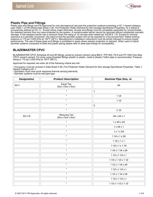
<strong>Plastic</strong> <strong>Pipe</strong> <strong>and</strong> <strong>Fittings</strong><br />
<strong>Plastic</strong> pipe <strong>and</strong> fittings are FM Approved for only aboveground wet pipe fire protection systems protecting a HC-1 hazard category<br />
(see Table 1 of FM Global Data Sheet 3-26, Fire Protection Water Dem<strong>and</strong> for Non-storage <strong>Sprinkler</strong>ed Properties, for a listing of<br />
occupancies defined as HC-1). Except where noted otherwise, all pipe <strong>and</strong> fittings must be completely separated by nonremovable,<br />
fire resistant barriers from any area protected by the system. A nonremovable barrier cannot be removed without substantial cosmetic<br />
damage. A fire-resistant barrier has a minimum finish fire rating of 15 minutes when tested per ASTM E 119. Except for minimal<br />
exposure at a sprinkler connection, the intent is that the sprinkler system will not be exposed to a fire environment. Rated working<br />
pressure is 175 psi (1205 kPa) at 120°F (49°C). Manufacturer's installation instructions must be strictly followed to ensure proper<br />
performance. The use of these pipes <strong>and</strong> fittings is prohibited in areas where seismic protection is required. When used in hybrid<br />
sprinkler systems composed of steel <strong>and</strong> plastic piping please refer to steel pipe listings for acceptability.<br />
<strong>BLAZEMASTER</strong> <strong>CPVC</strong><br />
<strong>BLAZEMASTER</strong> <strong>CPVC</strong> Schedule 40 <strong>and</strong> 80 fittings, joined by solvent cement using BM-5, TFP-500, FS-5 <strong>and</strong> FP-1000 One Step<br />
<strong>CPVC</strong> solvent cement. For joints using threaded fittings (plastic to plastic, metal to plastic) Teflon tape is recommended. Pressure<br />
rating is 175 psi (1205 kPa) at 150°F (66°C).<br />
Approved for exposed use when all of the following criteria are met:<br />
• Occupancy must be covered in Data Sheet 3-26, Fire Protection Water Dem<strong>and</strong> for Non-storage <strong>Sprinkler</strong>ed Properties, Table 1,<br />
Hazard Category HC-1.<br />
• <strong>Sprinkler</strong>s must have quick response thermal sensing elements.<br />
• <strong>Sprinkler</strong> systems must be wet pipe type.<br />
Designation Product Description Nominal <strong>Pipe</strong> Size, in.<br />
5011<br />
Equal Tee<br />
(Soc x Soc x Soc)<br />
" 1<br />
3⁄4<br />
" 1 1⁄4<br />
" 1 1⁄2<br />
" 2<br />
" 2 1⁄2<br />
5011-R<br />
Reducing Tee<br />
(Soc x Soc x Soc)<br />
3⁄4 x 3⁄4 x 1<br />
" 1 x 3⁄4 x 3⁄4<br />
" 1 x 3⁄4 x 1<br />
" 1 x 1 x 3⁄4<br />
" 1 1⁄4 x 1 x 3⁄4<br />
" 1 1⁄4 x 1 x 1<br />
" 1 1⁄4 x 1 x 1 1⁄4<br />
" 1 1⁄4 x 1 1⁄4 x 3⁄4<br />
" 1 1⁄4 x 1 1⁄4 x 1<br />
" 1 1⁄4 x 1 1⁄4 x 1 1⁄2<br />
" 1 1⁄2 x 1 1⁄4 x 3⁄4<br />
" 1 1⁄2 x 1 1⁄4 x 1<br />
" 1 1⁄2 x 1 1⁄2 x 3⁄4<br />
" 1 1⁄2 x 1 1⁄2 x 1<br />
" 1 1⁄2 x 1 1⁄2 x 1 1⁄2<br />
© 2007-2011 FM Approvals. All rights reserved. 1 of 6
" 1 1⁄2 x 1 1⁄2 x 2<br />
" 2 x 2 x 3⁄4<br />
" 2 x 2 x 1<br />
" 2 x 2 x 1 1⁄2<br />
" 2 1⁄2 x 2 1⁄2 x 1<br />
" 2 1⁄2 x 2 1⁄2 x 1 1⁄4<br />
" 2 1⁄2 x 2 1⁄2 x 1 1⁄2<br />
" 2 1⁄2 x 2 1⁄2 x 2<br />
" 3 x 3 x 1 1⁄2<br />
" 3 x 3 x 2 1⁄2<br />
" 3 x 3 x 2<br />
5007<br />
90° Elbow<br />
(Soc x Soc)<br />
" 1<br />
3⁄4<br />
" 1 1⁄4<br />
" 1 1⁄2<br />
" 2<br />
" 2 1⁄2<br />
" 3<br />
" 1 x 3⁄4<br />
5006<br />
45° Elbow<br />
(Soc x Soc)<br />
" 1<br />
3⁄4<br />
" 1 1⁄4<br />
" 1 1⁄2<br />
" 2<br />
" 2 1⁄2<br />
" 3<br />
5001<br />
Coupling<br />
(Soc x Soc)<br />
" 1<br />
3⁄4<br />
" 1 1⁄4<br />
" 1 1⁄2<br />
" 2<br />
" 2 1⁄2<br />
" 3<br />
© 2007-2011 FM Approvals. All rights reserved. 2 of 6
5001-G<br />
Grooved Adapter Coupling<br />
(Soc x Grv)<br />
1-1/4<br />
" 1-1/2<br />
" 2<br />
" 2-1/2<br />
" 3<br />
" 2 x 1-1/12<br />
5001-G-M<br />
5001-R<br />
Grooved Adapter Coupling<br />
(Soc x Grv)<br />
Reducing Coupling<br />
(Soc x Soc)<br />
"<br />
2-1/2 x 65 mm<br />
1 x 3⁄4<br />
1 1⁄4 x 1<br />
1 1⁄2 x 3⁄4<br />
" 1 1⁄2 x 1<br />
" 1 1⁄2 x 1 1⁄4<br />
" 2 x 1<br />
" 2 x 1 1⁄2<br />
5017<br />
Cap<br />
(Soc)<br />
" 1<br />
3⁄4<br />
" 1 1⁄4<br />
" 1 1⁄2<br />
" 2<br />
" 2 1⁄2<br />
" 3<br />
5018<br />
Reducing Bushing<br />
(Soc x Soc)<br />
1 x 3⁄4<br />
" 1 1⁄4 x 3⁄4<br />
" 1 1⁄4 x 1<br />
" 1 1⁄2 x 3⁄4<br />
" 1 1⁄2 x 1<br />
" 1 1⁄2 x 1 1⁄4<br />
" 2 x 3⁄4<br />
" 2 x 1<br />
" 2 x 1 1⁄4<br />
" 2 x 1 1⁄2<br />
" 2 1⁄2 x 1 1⁄4<br />
" 2 1⁄2 x 1 1⁄2<br />
© 2007-2011 FM Approvals. All rights reserved. 3 of 6
" 2 1⁄2 x 2<br />
" 3 x 2<br />
" 3 x 2 1⁄2<br />
5018<br />
Reducing Bushing<br />
(Spig x Soc)<br />
2-1/2 x 1<br />
" 3 x 1-1/2<br />
5018-S-BI<br />
Reducing Bushing<br />
(Spig x Fipt)<br />
1 x 1/2<br />
5035<br />
Cross<br />
(Soc x Soc x Soc x Soc)<br />
" 1<br />
3⁄4<br />
" 1 1⁄4<br />
" 1-1/2<br />
" 2<br />
" 2-1/2<br />
" 3<br />
" 1 x 3⁄4 x 1 x 3⁄4<br />
5051-H<br />
Flange<br />
(Soc)<br />
" 1<br />
3⁄4<br />
" 1 1⁄4<br />
" 1 1⁄2<br />
" 2<br />
" 2 1⁄2<br />
" 3<br />
5019-H<br />
Blind Flange<br />
(Soc)<br />
" 1<br />
3⁄4<br />
" 1 1⁄4<br />
" 1 1⁄2<br />
" 2<br />
" 2 1⁄2<br />
" 3<br />
5051-A Van Stone Flange (Soc) 3<br />
5051-2-A Van Stone Flange (Spig) 3<br />
© 2007-2011 FM Approvals. All rights reserved. 4 of 6
5003-BI<br />
5003-2-BI<br />
5004-BI<br />
5004-2-S-BI<br />
5012-S-BI<br />
Female Adapter<br />
with brass thread insert<br />
(Soc x Fipt)<br />
Female Adapter<br />
with brass thread insert<br />
(Spig x Fipt)<br />
Male Adapter<br />
with brass thread insert<br />
(Soc x Mipt)<br />
Female <strong>Sprinkler</strong> Head Adapter<br />
with brass thread insert<br />
(Spig x Fipt)<br />
<strong>Sprinkler</strong> Head Tee<br />
with brass thread insert<br />
(Soc x Soc x Fipt)<br />
3⁄4<br />
1<br />
1 1⁄4<br />
1 1⁄2<br />
2<br />
3⁄4<br />
1<br />
3⁄4<br />
1<br />
1 1⁄4<br />
1 1⁄2<br />
2<br />
3⁄4 x 1⁄2<br />
1 x 1⁄2<br />
3⁄4 x 3⁄4 x 1⁄2<br />
1 x 3⁄4 x 1⁄2<br />
1 x 1 x 1⁄2<br />
" 1 x 1 x 1<br />
" 1 x 1⁄2 x 1<br />
5012R-S-BI<br />
5007-3-S-BI<br />
5003-S3BT<br />
5003-S-BTT<br />
5003-BI-BSP<br />
5033-E<br />
"<br />
"<br />
"<br />
Female <strong>Sprinkler</strong> Head Reducing<br />
Tee with brass thread insert<br />
(Soc x Soc x Fipt)<br />
90° <strong>Sprinkler</strong> Head Elbow<br />
with brass thread insert<br />
(Soc x Fipt)<br />
Female Adapter<br />
with brass thread insert<br />
Female Adapter<br />
with brass thread insert<br />
Female Adapter<br />
with brass British thread insert<br />
<strong>CPVC</strong> Union<br />
(Soc x Soc)<br />
1 1⁄4 x 1 1⁄4 x 1⁄2<br />
1 1⁄2 x 1 1⁄2 x 1⁄2<br />
2 x 2 x 1⁄2<br />
1 1⁄4 x 1 x 1⁄2<br />
1 1⁄2 x 1 1⁄4 x 1⁄2<br />
2 x 1 1⁄2 x 1⁄2<br />
3⁄4 x 1⁄2<br />
1 x 1⁄2<br />
1 x 3⁄4<br />
1 1⁄4 x 1⁄2<br />
3⁄4 x 1⁄2<br />
1 x 1⁄2<br />
3⁄4 x 1⁄2<br />
1 x 1⁄2<br />
1<br />
1-1/4<br />
1-1/2<br />
2<br />
3⁄4<br />
" 1<br />
5033-E-3<br />
<strong>CPVC</strong> Union<br />
(Soc x Fipt)<br />
3⁄4<br />
" 1<br />
© 2007-2011 FM Approvals. All rights reserved. 5 of 6
Soc = Solvent Weld Socket<br />
Spig = Spigot End<br />
Fipt = Female Iron <strong>Pipe</strong> Thread<br />
Mipt = Male Iron <strong>Pipe</strong> Thread<br />
Grv = Grooved<br />
Company Name: NIBCO Inc<br />
Company Address: 1516 Middlebury St, Elkhart, Indiana 46516, USA<br />
Company Website: http://www.nibco.com<br />
Listing Country: United States of America<br />
Certification Type: FM Approved<br />
© 2007-2011 FM Approvals. All rights reserved. 6 of 6