

ST 3000 Smart Transmitter - Merkantile
ST 3000 Smart Transmitter - Merkantile
ST 3000 Smart Transmitter - Merkantile

Create successful ePaper yourself
Turn your PDF publications into a flip-book with our unique Google optimized e-Paper software.
<strong>ST</strong> <strong>3000</strong> <strong>Smart</strong> <strong>Transmitter</strong><br />
Series 900 Absolute Pressure Models<br />
<strong>ST</strong>A922/<strong>ST</strong>A92L 0 to 780 mmHgA<br />
<strong>ST</strong>A940/<strong>ST</strong>A94L 0 to 500 psia<br />
Introduction<br />
0 to 1,040 mbarA<br />
0 to 35 barA<br />
34-<strong>ST</strong>-03-66<br />
1/24/06<br />
Specification and<br />
Model Selection<br />
Guide<br />
In 1983, Honeywell introduced the first<br />
<strong>Smart</strong> Pressure <strong>Transmitter</strong>― the <strong>ST</strong><br />
<strong>3000</strong> ® . In 1989, Honeywell launched<br />
the first all digital, bi-directional protocol<br />
for smart field devices. Today, its<br />
<strong>ST</strong> <strong>3000</strong> Series 900 Absolute Pressure<br />
<strong>Transmitter</strong>s continue to bring proven<br />
“smart” technology to a wide spectrum<br />
of pressure measurement applications.<br />
Honeywell absolute pressure<br />
transmitters are used in applications in<br />
which high accuracy in the vacuum<br />
range of pressure is needed. Typical<br />
applications include low-pressure<br />
measurement in vacuum distillation<br />
columns, where energy savings are<br />
directly proportional to the vacuum in<br />
the column. Honeywell transmitters can<br />
be used in a wide spectrum of<br />
hazardous environments in perfect<br />
safety to provide proven, repeatable<br />
pressure measurements.<br />
All <strong>ST</strong> <strong>3000</strong> transmitters can provide a<br />
4-20 mA output, Honeywell Digitally<br />
Enhanced (DE) output, HART * output,<br />
or FOUNDATION Fieldbus output.<br />
When digitally integrated with<br />
Honeywell’s Process Knowledge<br />
System, EXPERION PKS,<br />
<strong>ST</strong> <strong>3000</strong> instruments provide a more<br />
accurate process variable as well as<br />
advanced diagnostics.<br />
Honeywell’s cost-effective <strong>ST</strong> <strong>3000</strong><br />
S900 transmitters lead the industry in<br />
reliability and stability:<br />
• Stability = +/-0.01% per year<br />
• Reliability = 470 years MTBF<br />
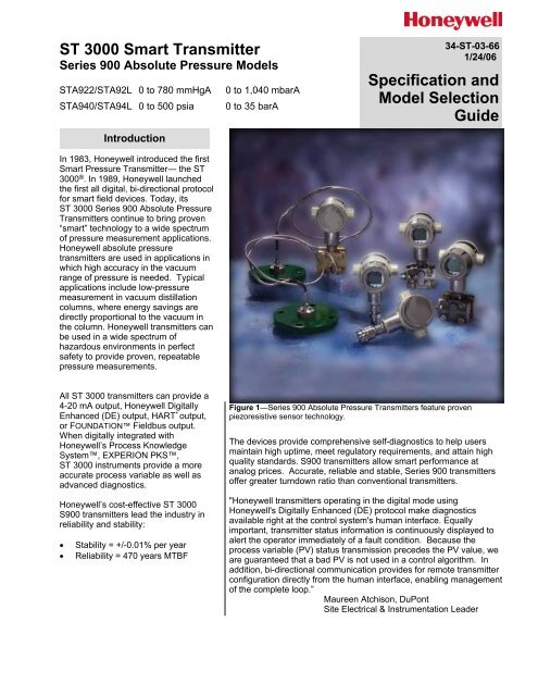
Figure 1—Series 900 Absolute Pressure <strong>Transmitter</strong>s feature proven<br />
piezoresistive sensor technology.<br />
The devices provide comprehensive self-diagnostics to help users<br />
maintain high uptime, meet regulatory requirements, and attain high<br />
quality standards. S900 transmitters allow smart performance at<br />
analog prices. Accurate, reliable and stable, Series 900 transmitters<br />
offer greater turndown ratio than conventional transmitters.<br />
"Honeywell transmitters operating in the digital mode using<br />
Honeywell's Digitally Enhanced (DE) protocol make diagnostics<br />
available right at the control system's human interface. Equally<br />
important, transmitter status information is continuously displayed to<br />
alert the operator immediately of a fault condition. Because the<br />
process variable (PV) status transmission precedes the PV value, we<br />
are guaranteed that a bad PV is not used in a control algorithm. In<br />
addition, bi-directional communication provides for remote transmitter<br />
configuration directly from the human interface, enabling management<br />
of the complete loop.”<br />
Maureen Atchison, DuPont<br />
Site Electrical & Instrumentation Leader
34-<strong>ST</strong>-03-66<br />
Page 2<br />
Description<br />
The <strong>ST</strong> <strong>3000</strong> transmitter can replace any 4 to 20 mA output transmitter in<br />
use today and operates over a standard two-wire system.<br />
The measuring means is a piezoresistive sensor, which actually contains<br />
three sensors in one. It contains a differential pressure sensor, a<br />
temperature sensor, and a static pressure sensor.<br />
Microprocessor-based electronics provide higher span-turndown ratio,<br />
improved temperature and pressure compensation, and improved<br />
accuracy.<br />
The transmitter’s meter body and electronics housing resist shock,<br />
vibration, corrosion, and moisture. The electronics housing contains a<br />
compartment for the single-board electronics, which is isolated from an<br />
integral junction box. The single-board electronics is replaceable and<br />
interchangeable with any other <strong>ST</strong> <strong>3000</strong> Series 100 or Series 900 model<br />
transmitter.<br />
Like other Honeywell transmitters, the <strong>ST</strong> <strong>3000</strong> features two-way<br />
communication between the operator and the transmitter through our<br />
<strong>Smart</strong> Field Configurator (SFC). You can connect the SFC anywhere that<br />
you can access the transmitter signal lines.<br />
The SCT <strong>3000</strong> <strong>Smart</strong>line ® Configuration Toolkit provides an easy way to<br />
configure instruments using a personal computer. The toolkit enables<br />
configuration of devices before shipping or installation. The SCT <strong>3000</strong><br />
can operate in the offline mode to configure an unlimited number of<br />
devices. The database can then be loaded downline during<br />
commissioning.<br />
Features<br />
• Choice of linear or square<br />
root output conformity is a<br />
simple configuration<br />
selection.<br />
• Direct digital integration with<br />
Experion PKS and other<br />
control systems provides local<br />
measurement accuracy to the<br />
system level without adding<br />
typical A/D and D/A converter<br />
inaccuracies.<br />
• Unique piezoresistive sensor<br />
automatically compensates<br />
input for temperature and<br />
static pressure. Added<br />
“smart” features include<br />
configuring lower and upper<br />
range values, simulating<br />
accurate analog output, and<br />
selecting preprogrammed<br />
engineering units for display.<br />
• <strong>Smart</strong> transmitter capabilities<br />
with local or remote<br />
interfacing means significant<br />
manpower efficiency<br />
improvements in<br />
commissioning, start-up, and<br />
ongoing maintenance<br />
functions.
34-<strong>ST</strong>-03-66<br />
Page 3<br />
Specifications<br />
Operating Conditions – All Models<br />
Parameter<br />
Reference<br />
Condition<br />
(at zero static)<br />
Rated Condition Operative Limits Transportation and<br />
Storage<br />
°C °F °C °F °C °F °C °F<br />
Ambient Temperature 25±1 77±2 -25 to 70 -13 to 158 -40 to 85 -40 to 185 -55 to 125 -67 to 257<br />
Meter Body Temperature<br />
<strong>ST</strong>A922/<strong>ST</strong>A92L 25±1 77±2 See Figure 2 See Figure 2 -55 to 125 -67 to 257<br />
<strong>ST</strong>A940/<strong>ST</strong>A94L 25±1 77±2 -25 to 70 -13 to 158 -40 to 80 -40 to 176 -55 to 125 -67 to 257<br />
Humidity %RH 10 to 55 0 to 100 0 to 100 0 to 100<br />
Vacuum Region - Minimum<br />
Pressure <strong>ST</strong>A922/<strong>ST</strong>A92L<br />
<strong>ST</strong>A940/<strong>ST</strong>A94L<br />
Supply Voltage, Current,<br />
and Load Resistance<br />
Maximum Allowable<br />
Working Pressure (MAWP)<br />
(<strong>ST</strong> <strong>3000</strong> products are rated to<br />
Maximum Allowable Working<br />
Pressure)<br />
See Figure 2.<br />
Operate within specifications above 25 mmHgA (33 mbarA). Short term exposure (2 hours<br />
at 70°C/158°F) to full vacuum will not result in damage.<br />
Voltage Range: 10.8 to 42.4 Vdc at terminals<br />
Current Range: 3.0 to 21.8 mA<br />
Load Resistance: 0 to 1440 ohms (as shown in Figure 3)<br />
<strong>ST</strong>A922/<strong>ST</strong>A92L = 1550 mmHgA, 2066 mbarA<br />
<strong>ST</strong>A940/<strong>ST</strong>A94L = 750 psia, 52 barA<br />
Units can withstand overpressure of 1.5X MAWP without damage.
34-<strong>ST</strong>-03-66<br />
Page 4<br />
1000<br />
9<br />
8<br />
7<br />
6<br />
5<br />
4<br />
] [<br />
] [<br />
Rated Operating Area<br />
Operative<br />
Limit<br />
3<br />
Silicone Oil<br />
DC-200<br />
2<br />
100<br />
9<br />
8<br />
7<br />
6<br />
Measured<br />
5<br />
Pressure<br />
4<br />
mmHgA<br />
CTFE<br />
25 mmHgA<br />
(33.3 mbarA)<br />
3<br />
2<br />
10<br />
9<br />
8<br />
7<br />
6<br />
5<br />
4<br />
Silicone Oil<br />
DC 704<br />
LEGEND:<br />
3<br />
Rated operating area<br />
2<br />
1.0<br />
9<br />
8<br />
7<br />
6<br />
5<br />
4<br />
3<br />
] [<br />
Contact Marketing<br />
Applications for "special"<br />
quote.<br />
NOTE: Short term exposure (2 hours at<br />
70°C/158°F) to hard vacuum will not<br />
result in damage.<br />
2<br />
0.1<br />
] [<br />
-40 -30 -20 0 40 50 60 70 80 90 100 110 120 ÞC<br />
-40 -22 -4 32 104 122 140 158 176 194 212 230 248 ÞF<br />
Meter Body Temperature<br />
23065<br />
Figure 2—Measured pressure versus meter body temperature chart for model <strong>ST</strong>A922/<strong>ST</strong>A92L
34-<strong>ST</strong>-03-66<br />
Page 5<br />
1440<br />
1200<br />
= Operating<br />
Area<br />
Loop<br />
Resistance<br />
(ohms)<br />
800<br />
650<br />
450<br />
250<br />
NOTE: A minimum of 250<br />
0hms of loop resistance is<br />
necessary to support<br />
communications. Loop<br />
resistance equals barrier<br />
resistance plus wire<br />
resistance plus receiver<br />
resistance. Also 45 volt<br />
operation is permitted if<br />
not an intrinsically safe<br />
installation.<br />
0 10.8 16.28 20.63 25 28.3 37.0 42.4<br />
Operating Voltage (Vdc)<br />
21012<br />
Figure 3—Supply voltage and loop resistance chart<br />
Performance Under Rated Conditions* - Models <strong>ST</strong>A922/<strong>ST</strong>A92L (0 to 780 mmHgA/1040 mbarA)<br />
Parameter<br />
Description<br />
Upper Range Limit mmHgA<br />
mbarA<br />
780 (0°C/32°F is standard reference temperature for mmHg range.)<br />
1040<br />
Minimum Span<br />
mmHgA<br />
mbarA<br />
50<br />
67<br />
Turndown Ratio 15 to 1<br />
Zero Suppression<br />
Accuracy (Reference – Includes<br />
combined effects of linearity,<br />
hysteresis, and repeatability)<br />
• Accuracy includes residual error<br />
after averaging successive<br />
readings.<br />
• For FOUNDATION Fieldbus use<br />
Digital Mode specifications. For<br />
HART use Analog Mode<br />
specifications.<br />
Zero Temperature Effect per<br />
28°C (50°F)<br />
No limit except minimum span within 0 (zero) to +100% URL.<br />
In Analog Mode: ±0.10% of calibrated span or upper range value (URV), whichever is<br />
greater, terminal based.<br />
For URV below reference point (90 mmHgA), accuracy equals:<br />
±0.05 + 0.05 (<br />
90 mmHgA<br />
)<br />
span mmHgA<br />
or ±0.05 + 0.05 (<br />
120 mbarA<br />
span mbarA )<br />
in % of span<br />
In Digital Mode: ±0.075% of calibrated span or upper range value (URV), whichever<br />
is greater, terminal based.<br />
For URV below reference point (90 mmHgA), accuracy equals:<br />
±0.025 + 0.05 (<br />
90 mmHgA<br />
)<br />
span mmHgA<br />
or ±0.025 + 0.05 (<br />
120 mbarA<br />
span mbarA )<br />
In Analog Mode: ±0.1625% of span.<br />
For URV below reference point (180 mmHgA), effect equals:<br />
±0.0125 + 0.15 (<br />
180 mmHgA<br />
)<br />
span mmHgA<br />
or ±0.0125 + 0.15 (<br />
240 mbarA<br />
span mbarA )<br />
In Digital Mode: ±0.15% of span.<br />
For URV below reference point (180 mmHgA), effect equals:<br />
±0.15 (<br />
180 mmHgA<br />
)<br />
span mmHgA<br />
or ±0.15 (<br />
240 mbarA<br />
span mbarA )<br />
in % of span<br />
in % of span<br />
in % of span<br />
* Performance specifications are based on reference conditions of 25°C (77°F), 10 to 55% RH, and 316L Stainless Steel barrier diaphragm.
34-<strong>ST</strong>-03-66<br />
Page 6<br />
Performance Under Rated Conditions - Models <strong>ST</strong>A922/<strong>ST</strong>A92L (0 to 780 mmHgA/1040 mbarA),<br />
Continued<br />
Parameter<br />
Combined Zero and Span<br />
Temperature Effect per 28°C<br />
(50°F)<br />
Description<br />
In Analog Mode: ±0.25% of span.<br />
For URV below reference point (180 mmHgA), effect equals:<br />
±0.10 + 0.15 (<br />
180 mmHgA<br />
)<br />
span mmHgA<br />
or ±0.10 + 0.15 (<br />
240 mbarA<br />
span mbarA )<br />
In Digital Mode: ±0.225% of span.<br />
For URV below reference point (180 mmHgA), effect equals:<br />
±0.075 + 0.15 (<br />
180 mmHgA<br />
)<br />
span mmHgA<br />
or ±0.075 + 0.15 (<br />
240 mbarA<br />
span mbarA )<br />
in % of span<br />
in % of span<br />
Performance Under Rated Conditions* - Models <strong>ST</strong>A940/<strong>ST</strong>A94L (0 to 500 psia/35 barA)<br />
Parameter<br />
Upper Range Limit<br />
Minimum Span<br />
psia<br />
barA<br />
psia<br />
barA<br />
500<br />
35<br />
20<br />
1.4<br />
Turndown Ratio 25 to 1<br />
Zero Suppression<br />
Accuracy (Reference – Includes<br />
combined effects of linearity,<br />
hysteresis, and repeatability)<br />
• Accuracy includes residual error<br />
after averaging successive<br />
readings.<br />
• For FOUNDATION Fieldbus use<br />
Digital Mode specifications. For<br />
HART use Analog Mode<br />
specifications.<br />
Zero Temperature Effect per<br />
28°C (50°F)<br />
Combined Zero and Span<br />
Temperature Effect per 28°C<br />
(50°F)<br />
Description<br />
No limit except minimum span within 0 (zero) to +100% URL.<br />
In Analog Mode: ±0.10% of calibrated span or upper range value (URV), whichever is<br />
greater, terminal based.<br />
For URV below reference point (20 psia), accuracy equals:<br />
±0.05 + 0.05 (<br />
20 psia<br />
)<br />
span psia<br />
or ±0.05 + 0.05 (<br />
1.4 barA<br />
span barA )<br />
in % of span<br />
In Digital Mode: ±0.075% of calibrated span or upper range value (URV), whichever<br />
is greater, terminal based.<br />
For URV below reference point (20 psia), accuracy equals:<br />
±0.025 + 0.05 (<br />
20 psia<br />
)<br />
span psia<br />
or ±0.025 + 0.05 (<br />
1.4 barA<br />
span barA )<br />
In Analog Mode: ±0.1625% of span.<br />
For URV below reference point (50 psia), effect equals:<br />
±0.0125 + 0.15 (<br />
50 psia<br />
)<br />
span psia<br />
or ±0.0125 + 0.15 (<br />
3.5 barA<br />
span barA )<br />
In Digital Mode: ±0.15% of span.<br />
For URV below reference point (50 psia), effect equals:<br />
±0.15 (<br />
50 psia<br />
)<br />
span psia<br />
or ±0.15 (<br />
3.5 barA<br />
span barA )<br />
in % of span<br />
In Analog Mode: ±0.25% of span.<br />
For URV below reference point (50 psia), effect equals:<br />
±0.10 + 0.15 (<br />
50 psia<br />
)<br />
span psia<br />
or ±0.10 + 0.15 (<br />
3.5 barA<br />
span barA )<br />
In Digital Mode: ±0.225% of span.<br />
For URV below reference point (50 psia), effect equals:<br />
±0.075 + 0.15 (<br />
50 psia<br />
)<br />
span psia<br />
or ±0.075 + 0.15 (<br />
3.5 barA<br />
span barA )<br />
in % of span<br />
in % of span<br />
in % of span<br />
in % of span<br />
* Performance specifications are based on reference conditions of 25°C (77°F), 10 to 55% RH, and 316L Stainless Steel barrier diaphragm.
Performance Under Rated Conditions - General for all Models<br />
Parameter<br />
Output (two-wire)<br />
Supply Voltage Effect<br />
Damping Time Constant<br />
CE Conformity (Europe)<br />
NAMUR NE 43 Compliance<br />
Option<br />
Lightning Protection Option<br />
(Code “LP”)<br />
Description<br />
Analog 4 to 20 mA or DE digital communications mode. Options available for<br />
FOUNDATION Fieldbus and HART protocol.<br />
0.005% of span per volt.<br />
Adjustable from 0 to 32 seconds digital damping.<br />
89/336/EEC, Electromagnetic Compatibility (EMC) Directive.<br />
34-<strong>ST</strong>-03-66<br />
Page 7<br />
<strong>Transmitter</strong> failure information is generated when the measuring information is invalid or<br />
no longer present. Failure information is transmitted as a current signal but outside the<br />
normal 4-20 mA measurement signal level. <strong>Transmitter</strong> failure values are: ≤ 3.6 mA<br />
and ≥ 21.0 mA. The normal signal range is ≥ 3.8 mA and ≤ 20.5 mA.<br />
Leakage Current: 10 microamps max. @ 42.4 VDC, 93°C<br />
Impulse Rating: 10/20 µ sec. 5,000 Amps (50 strikes) 10,000 Amps (20 strikes)<br />
(rise/decay) 10/1000 µ sec. 250 Amps (1000 strikes) 500 Amps (400 strikes)<br />
Physical and Approval Bodies<br />
Parameter<br />
Barrier Diaphragms Material 316L SS, Hastelloy C-276<br />
Description<br />
Process Head Material <strong>ST</strong>A922/<strong>ST</strong>A940: 316 SS, Carbon Steel (zinc-plated), Hastelloy C-276<br />
<strong>ST</strong>A92L/<strong>ST</strong>A94L: 316 SS<br />
Head Gaskets<br />
<strong>ST</strong>A922/<strong>ST</strong>A940: Viton is standard. Teflon is optional but not recommended for leakproof<br />
service under full vacuum. Graphite is also optional.<br />
Meter Body Bolting<br />
Mounting Bracket<br />
Fill Fluid<br />
Electronic Housing<br />
Process Connections<br />
Wiring<br />
Mounting<br />
<strong>ST</strong>A922/<strong>ST</strong>A940: Carbon Steel (zinc-plated, standard) or A286 SS (NACE) bolts and<br />
302/304 SS (NACE) nuts for heads.<br />
Carbon Steel (zinc-plated) or Stainless Steel angle bracket or Carbon Steel flat<br />
bracket available.<br />
Silicone DC 200 oil or CTFE (Chlorotrifluoroethylene)<br />
Note that DC 704 is available – Please contact Product Marketing.<br />
Epoxy-Polyester hybrid paint. Low Copper-Aluminum. Meets NEMA 4X (watertight)<br />
and NEMA 7 (explosion proof). Stainless steel optional.<br />
<strong>ST</strong>A922/<strong>ST</strong>A940: 1/2-inch F-NPT, DIN<br />
<strong>ST</strong>A92L/<strong>ST</strong>A94L: 1/2-inch F-NPT, 1/2 inch M-NPT, 9/16 AMINCO, DIN 19213<br />
Accepts up to 16 AWG (1.5 mm diameter).<br />
Dimensions See Figures 5 and 5a.<br />
Net Weight<br />
Approval Bodies<br />
- Hazardous Areas<br />
- Canadian Registration<br />
Number (CRN)<br />
Can be mounted in virtually any position using the standard mounting bracket. Bracket<br />
is designed to mount on 2-inch (50 mm) vertical or horizontal pipe. See Figures 4 and<br />
4a.<br />
<strong>ST</strong>A922/<strong>ST</strong>A940: 10 pounds (4.5 Kg) <strong>ST</strong>A92L/<strong>ST</strong>A94L: 4.5 pounds (2 kg)<br />
Approved as explosion proof and intrinsically safe for use in Class I, Division 1, Groups<br />
A, B, C, D locations, and nonincendive for Class I, Division 2, Groups A, B, C, D<br />
locations. Approved EEx ia IIC T4, T5, T6 and EEx d IIC T5, T6 per ATEX standards.<br />
See attached Model Selection Guide for options.<br />
- All <strong>ST</strong> <strong>3000</strong> model designs, except <strong>ST</strong>G19L, <strong>ST</strong>G99L, <strong>ST</strong>G170, <strong>ST</strong>G180, have been<br />
registered in all provinces and territories in Canada and are marked CRN: 0F8914.5C.
34-<strong>ST</strong>-03-66<br />
Page 8<br />
Pressure Equipment Directive<br />
(97/23/EC)<br />
The <strong>ST</strong> <strong>3000</strong> pressure transmitters listed in this Specification have no pressurized<br />
internal volume or have a pressurized internal volume rated less than 1,000 bar<br />
(14,500 psig) and/or have a maximum volume of less than 0.1 liter. Therefore, these<br />
transmitters are either; not subject to the essential requirements of the directive<br />
97/23/EC (PED, Annex 1) and shall not have the CE mark, or the manufacturer has<br />
the free choice of a module when the CE mark is required for pressures > 200 bar<br />
(2,900 psig).<br />
NOTE: Pressure transmitters that are part of safety equipment for the protection of piping (systems) or vessel(s) from<br />
exceeding allowable pressure limits, (equipment with safety functions in accordance with Pressure Equipment Directive<br />
97/23/EC article 1, 2.1.3), require separate examination.<br />
24267<br />
Figure 4—Examples of typical mounting positions<br />
Figure 4a Examples of typical mounting positions for in-line models<br />
24268
34-<strong>ST</strong>-03-66<br />
Page 9<br />
Reference Dimensions: millimeters<br />
inches<br />
3.6<br />
0.14<br />
Plug<br />
135<br />
5.32<br />
With<br />
<strong>Smart</strong><br />
meter<br />
Removal<br />
Clearance<br />
for All Caps<br />
45.7<br />
1.8<br />
82.9<br />
3.26<br />
53.1<br />
2.09<br />
Without<br />
meter<br />
94.9<br />
3.74<br />
65.1<br />
2.56<br />
Without<br />
meter<br />
1/2"<br />
NPT<br />
171.3<br />
6.74<br />
Optional<br />
Meters<br />
106.2<br />
4.18<br />
Optional<br />
external<br />
ground<br />
23.5<br />
.925<br />
Rotational<br />
Lock<br />
262.1<br />
10.32<br />
1/2" NPT<br />
Pressure<br />
Connection<br />
6<br />
0.24<br />
21.2<br />
0.83<br />
Mounting Holes<br />
M8 x 1.25 (2)<br />
71.1<br />
2.80 SQ. 24250<br />
50<br />
1.97<br />
53.6<br />
2.11<br />
74.4<br />
2.93<br />
Figure 5—Typical mounting dimensions for reference
34-<strong>ST</strong>-03-66<br />
Page 10<br />
With<br />
<strong>Smart</strong><br />
meter<br />
82.9<br />
3.26<br />
94.9<br />
3.74<br />
With<br />
Analog<br />
meter<br />
Removal<br />
Clearance<br />
for All Caps<br />
45.7<br />
1.8<br />
53.1<br />
2.09<br />
Without<br />
meter<br />
65.1<br />
2.56<br />
Without<br />
meter<br />
135<br />
5.32<br />
3.6<br />
0.14<br />
Plug<br />
23.5<br />
.925<br />
55.3<br />
2.18<br />
1/2"<br />
NPT<br />
Optional<br />
meters<br />
213.3 / 238.3*<br />
8.40 / 9.38<br />
Optional<br />
external<br />
ground<br />
158 / 183*<br />
6.22 / 7.20<br />
Rotational<br />
lock<br />
Other Connectors<br />
44.5 38.1<br />
1.75 1.5 or<br />
38.1<br />
1.5<br />
1/2" NPT<br />
Pressure<br />
Connection<br />
9/16 Aminco<br />
Pressure Connection<br />
½” NPT male<br />
DIN19213<br />
*Dimensions vary due to slight differences in electronics housing designs.<br />
24270<br />
Bottom view of DIN<br />
Figure 5a - Typical mounting dimensions for in-line models
34-<strong>ST</strong>-03-66<br />
Page 11<br />
Options<br />
Ordering Information<br />
Mounting Bracket<br />
The angle mounting bracket is<br />
available in either zinc-plated<br />
carbon steel or stainless steel and<br />
is suitable for horizontal or vertical<br />
mounting on a two inch (50<br />
millimeter) pipe, as well as wall<br />
mounting. An optional flat<br />
mounting bracket is also available<br />
in carbon steel for two inch (50<br />
millimeter) pipe mounting.<br />
Indicating Meter<br />
(ME and SM Options)<br />
Two integral meter options are<br />
available. An analog meter (option<br />
ME) is available with a 0 to 100%<br />
linear scale. The <strong>Smart</strong> Meter<br />
(option SM) provides an LCD<br />
display for both analog and digital<br />
output and can be configured to<br />
display pressure in pre-selected<br />
engineering units.<br />
Lightning Protection<br />
(Option LP)<br />
A terminal block is available with<br />
circuitry that protects the<br />
transmitter from transient surges<br />
induced by nearby lightning<br />
strikes.<br />
HART Protocol Compatibility<br />
(Option HC)<br />
An optional electronics module is<br />
available for the <strong>ST</strong> <strong>3000</strong> that<br />
provides HART Protocol<br />
compatibility. <strong>Transmitter</strong>s with the<br />
HART Option are compatible with<br />
the AMS System. (Contact your<br />
AMS Supplier if an upgrade is<br />
required.)<br />
Indicator Configuration<br />
(Option CI)<br />
Provides custom configuration of<br />
<strong>Smart</strong> Meters.<br />
Tagging (Option TG)<br />
Up to 30 characters can be added<br />
on the stainless steel nameplate<br />
mounted on the transmitter’s<br />
electronics housing at no extra cost.<br />
Note that a separate nameplate on<br />
the meter body contains the serial<br />
number and body-related data. A<br />
stainless steel wired on tag with<br />
additional data of up to 4 lines of 28<br />
characters is also available. The<br />
number of characters for tagging<br />
includes spaces.<br />
<strong>Transmitter</strong> Configuration<br />
(Option TC)<br />
The factory can configure the<br />
transmitter linear/square root<br />
extraction, damping time, LRV,<br />
URV and mode (analog/digital) and<br />
enter an ID tag of up to eight characters<br />
and scratchpad information<br />
as specified.<br />
Custom Calibration and ID in<br />
Memory (Option CC)<br />
The factory can calibrate any range<br />
within the scope of the transmitter’s<br />
range and enter an ID tag of up to<br />
eight characters in the transmitter’s<br />
memory.<br />
FOUNDATION Fieldbus<br />
(Option FF)<br />
Equips transmitter with FF<br />
protocol for use in 31.25 kbit/s<br />
FF networks. See document<br />
34-<strong>ST</strong>-03-72 for additional<br />
information on <strong>ST</strong> <strong>3000</strong><br />
Fieldbus transmitters.<br />
Contact your nearest Honeywell sales<br />
office, or<br />
In the U.S.:<br />
Honeywell<br />
Industrial Automation & Control<br />
2500 W. Union Hills Ave<br />
Phoenix, AZ 85053<br />
1-800-288-7491<br />
In Canada:<br />
The Honeywell Centre<br />
155 Gordon Baker Rd.<br />
North York, Ontario M2H 3N7<br />
1-800-461-0013<br />
In Latin America:<br />
Honeywell Inc.<br />
480 Sawgrass Corporate Parkway,<br />
Suite 200<br />
Sunrise, FL 33325<br />
(954) 845-2600<br />
In Europe and Africa:<br />
Honeywell S. A.<br />
Avenue du Bourget 1<br />
1140 Brussels, Belgium<br />
In Eastern Europe:<br />
Honeywell Praha,<br />
s.r.o. Budejovicka 1<br />
140 21 Prague 4,<br />
Czech Republic<br />
In the Middle East:<br />
Honeywell Middle East Ltd.<br />
Khalifa Street,<br />
Sheikh Faisal Building<br />
Abu Dhabi, U. A. E.<br />
In Asia:<br />
Honeywell Asia Pacific Inc.<br />
Honeywell Building,<br />
17 Changi Business Park Central 1<br />
Singapore 486073<br />
Republic of Singapore<br />
In the Pacific:<br />
Honeywell Pty Ltd.<br />
5 Thomas Holt Drive<br />
North Ryde NSW Australia 2113<br />
(61 2) 9353 7000<br />
In Japan:<br />
Honeywell K.K.<br />
14-6 Shibaura 1-chrome<br />
Minato-ku, Tokyo, Japan 105-0023<br />
Specifications are subject to change without notice.<br />
(Note that specifications may differ slightly for transmitters manufactured before<br />
October 30, 1995.)<br />
Or, visit Honeywell on the World Wide<br />
Web at: http://www.honeywell.com
34-<strong>ST</strong>-03-66<br />
Page 12<br />
Model Selection Guide (34-<strong>ST</strong>-16-26)<br />
Instructions<br />
Select the desired Key Number. The arrow to the right marks the selection available.<br />
Make one selection from each table, I and II, using the column below the proper arrow.<br />
Select as many Table III options as desired (if no options or approvals are desired, specify 9X).<br />
A (•) denotes unrestricted availability. A letter denotes restricted availability.<br />
Restrictions follow Table IV.<br />
Key Number I II III (Optional) IV<br />
_ _ _ _ _ _ - _ _ _ - _ _ _ _ _ - _ _, _ _, _ _ + XXXX<br />
KEY NUMBER Selection Availability<br />
Span<br />
Gage 0-20 to 0-500 psi/0-1.4 to 0-35 bar <strong>ST</strong>G944<br />
Pressure 0-300 to 0-<strong>3000</strong> psi/0-21 to 0-210 bar <strong>ST</strong>G974<br />
Absolute 0-50 to 0-780 mmHgA/0-67 to 0-1040 mbarA <strong>ST</strong>A922<br />
Pressure 0-20 to 0-500 psia/0-1.4 to 0-35 barA <strong>ST</strong>A940<br />
TABLE I - METER BODY<br />
Wetted Vent/Drain Barrier<br />
Process Head *** Valve ** Diaphragms<br />
Carbon Steel * 316 SS 316L SS A _ _ • •<br />
Carbon Steel * 316 SS Hastelloy C B _ _ • •<br />
Material Carbon Steel * 316 SS Monel C _ _ •<br />
of Carbon Steel * 316 SS Tantalum D _ _ •<br />
Construction 316 SS 316 SS 316L SS E _ _ • •<br />
316 SS 316 SS Hastelloy C F _ _ • •<br />
316 SS 316 SS Monel G _ _ •<br />
316 SS 316 SS Tantalum H _ _ •<br />
Hastelloy C Hastelloy C Hastelloy C J _ _ • •<br />
Hastelloy C Hastelloy C Tantalum K _ _ •<br />
Monel Monel Monel L _ _ •<br />
Fill Fluid Silicone DC200 **** _ 1 _ • •<br />
CTFE _ 2 _ • •<br />
Process Head 1/4" NPT _ _ A •<br />
Configuration 1/2" NPT with Adapter _ _ G t<br />
1/2" NPT _ _ G •<br />
TABLE II<br />
No Selection 00000 • •<br />
* Carbon Steel heads are zinc-plated. Not recommended for water service due to hydrogen migration.<br />
Use Stainless Steel heads.<br />
** Vent/Drains are Teflon coated for lubricity.<br />
*** The standard reference head for the <strong>ST</strong>G9XX is carbon steel (zinc-plated).<br />
See Table III for a stainless steel reference (HR) head option.<br />
**** If <strong>ST</strong>A922 operating below 50mm HgA, see Figure 2 in Specification 34-<strong>ST</strong>-03-65 and<br />
contact Marketing Applications for a "Special" Silicone DC704 quote.<br />
Note:<br />
End vent drain valve standard for <strong>ST</strong>G9XX.<br />
End vent drain valves are not available on <strong>ST</strong>A9XX.
34-<strong>ST</strong>-03-66<br />
Page 13<br />
Model Selection Guide (34-<strong>ST</strong>-16-26), cont.<br />
Effective Date: January 09, 2006<br />
<strong>ST</strong>A9<br />
<strong>ST</strong>G9<br />
Availability<br />
44 22<br />
TABLE III - OPTIONS Selection 74 40<br />
None 00 • •<br />
Communication Options<br />
HART ® Protocol Compatible Electronics HC e e b<br />
FOUNDATION Fieldbus Communications FF r r<br />
Indicating Meter Options<br />
Analog Meter (0-100 Even 0-10 Square Root) ME • •<br />
<strong>Smart</strong> Meter SM • •<br />
b<br />
Custom Configuration of <strong>Smart</strong> Meter CI m m<br />
Local Zero LZ x<br />
Local Zero and Span ZS s<br />
b<br />
<strong>Transmitter</strong> Housing & Electronics Options<br />
NAMUR Failsafe Software NE 15 15<br />
Lightning Protection LP • •<br />
Custom Calibration and I.D. in Memory CC • •<br />
<strong>Transmitter</strong> Configuration TC • •<br />
Write Protection WP • •<br />
316 SS Electronics Housing - with M20 Conduit Connections SH n n<br />
1/2" NPT to M20 316 SS Conduit Adapter (BASEEFA EEx d IIC) A1 n n<br />
1/2" NPT to 3/4" NPT 316 SS Conduit Adapter A2 i i<br />
b<br />
Stainless Steel Housing with M20 to 1/2" NPT 316 SS Conduit A3 i i<br />
Adapter (use for FM and CSA Approvals)<br />
Stainless Steel Customer Wired-On Tag TG • •<br />
(4 lines, 28 characters per line, customer supplied information)<br />
Stainless Steel Customer Wired-On Tag (blank) TB • •<br />
Low Temperature - -50 o C Ambient Limit LT z<br />
End Cap Live Circuit Warning Label in Spanish (only with ATEX 3D) SP a a<br />
End Cap Live Circuit Warning Label in Portuguese (only with ATEX 3D) PG a a b<br />
End Cap Live Circuit Warning Label in Italian (only with ATEX 3D) TL a a<br />
End Cap Live Circuit Warning Label in German (only with ATEX 3D) GE a a<br />
Meter Body Options<br />
A286 SS (NACE) Bolts and 304 SS (NACE) Nuts for Process Heads CR • •<br />
316 SS Bolts and 316 SS Nuts for Process Heads SS • b<br />
B7M Bolts and Nuts for Process Heads B7 •<br />
316 SS Adapter Flange - 1/2" NPT with CS Bolts S2 c<br />
316 SS Adapter Flange - 1/2" NPT with 316 SS Bolts S3 c<br />
316 SS Adapter Flange - 1/2" NPT with NACE A286 SS Bolts S4 c<br />
316 SS Adapter Flange - 1/2" NPT with B7M Bolts S5 c<br />
Hastelloy C Adapter Flange - 1/2" NPT with CS Bolts T2 c b<br />
Hastelloy C Adapter Flange - 1/2" NPT with 316 SS Bolts T3 c<br />
Monel Adapter Flange - 1/2" NPT with CS Bolts V2 c<br />
Monel Adapter Flange - 1/2" NPT with 316 SS Bolts V3 c<br />
316 SS Blind Adapter Flange with CS Bolts B3 •<br />
316 SS Blind Adapter Flange with 316 SS Bolts B4 •<br />
316 SS Blind Adapter Flange with NACE A286 SS Bolts B5 • b<br />
316 SS Blind Adapter Flange with B7M Bolts B6 •<br />
316 SS Center Vent Drain and Bushing CV •<br />
Side Vent/Drain (End Vent Drain is standard) SV •<br />
Viton Process Head Gaskets VT •<br />
Viton Adapter Flange Gaskets VF •<br />
316 SS Reference Head (Carbon Steel Standard) HR •<br />
Modified DIN Process Heads - 316 SS DN v<br />
Graphite Process Head Gasket GF • •<br />
<strong>Transmitter</strong> Mounting Bracket Options<br />
Mounting Bracket - Carbon Steel MB • •<br />
Mounting Bracket - 304 SS SB • • b<br />
Flat Mounting Bracket - Carbon Steel FB • •<br />
Table III continued next page
34-<strong>ST</strong>-03-66<br />
Page 14<br />
Model Selection Guide (34-<strong>ST</strong>-16-26), cont.<br />
<strong>ST</strong>A9<br />
<strong>ST</strong>G9<br />
Availability<br />
44 22<br />
TABLE III - OPTIONS (continued) Selection 74 40<br />
Diaphragm Options<br />
Gold plated diaphragm(s) on 316 SS G1 •<br />
Gold plated diaphragm(s) on Monel or Hastelloy ONLY G2 •<br />
Services/Certificates/Marine Type Approval Options<br />
User's Manual Paper Copy (Standard, HC, or FF ships accordingly) UM • •<br />
Clean <strong>Transmitter</strong> for Oxygen or Chlorine Service with Certificate 0X h h<br />
Over-Pressure Leak Test with F3392 Certificate TP • •<br />
Calibration Test Report and Certificate of Conformance (F3399) F1 • •<br />
Certificate of Conformance (F3391) F3 • •<br />
b<br />
Certificate of Origin (F0195) F5 • •<br />
FMEDA (SIL) Certificate F6 • •<br />
NACE Certificate (F0198) F7 o o<br />
Marine Type Approvals (DNV, ABS, BV & LR) MT 2 2<br />
Warranty Options<br />
Additional Warranty - 1 year W1 • •<br />
Additional Warranty - 2 years W2 • •<br />
Additional Warranty - 3 years W3 • •<br />
b<br />
Additional Warranty - 4 years W4 • •<br />
Approval<br />
Body Approval Type Location or Classification<br />
No hazardous location approvals 9X • •<br />
Explosion Proof Class I, Div. 1, Groups A,B,C,D<br />
Factory Dust Ignition Proof Class II, III Div. 1, Groups E,F,G<br />
Mutual Non-Incendive Class I, Div. 2, Groups A,B,C,D 1C • •<br />
Intrinsically Safe Class I, II, III, Div. 1, Groups<br />
A,B,C,D,E,F,G<br />
Explosion Proof Class I, Div. 1, Groups B,C,D<br />
CSA Dust Ignition Proof Class II, III, Div. 1, Groups E,F,G 2J f •<br />
Intrinsically Safe Class I, II, III, Div. 1, Groups<br />
A,B,C,D,E,F,G<br />
b<br />
SA Intrinsically Safe Ex ia IIC T4 4G • •<br />
(Australia) Non-Sparking Ex n IIC T6 (T4 with SM option)<br />
Intrinsically Safe, Ex II I G EEx ia IIC T4, T5,T6 3S • •<br />
Zone 0/1<br />
Flameproof, Ex II 2 G EEx d IIC T5, T6, 3D • •<br />
ATEX* Zone 1 Enclosure IP 66/67<br />
Non-Sparking, Ex II 3 G EEx nA, IIC T6 3N • •<br />
Zone 2 (Honeywell). Enclosure IP 66/67<br />
Multiple Marking** Ex II 1 G EEx ia IIC T4, T5, T6<br />
Int. Safe, Zone 0/1, or Ex II 2 G EEx d IIC T5, T6 3H • •<br />
Flameproof, Zone 1, or Ex II 3 G EEx nA, IIC T6 (Honeywell)<br />
Non-Sparking, Zone 2 Enclosure IP 66/67<br />
INMETRO Flameproof, Zone 1 Ex d IIC T5 6D • •<br />
(Brazil)<br />
*See ATEX installation requirements in the <strong>ST</strong> <strong>3000</strong> User's Manual<br />
** The user must determine the type of protection required for installation of the equipment. The user shall<br />
then check the box [] adjacent to the type of protection used on the equipment certification nameplate.<br />
Once a type of protection has been checked on the nameplate, subsequently the equipment shall not<br />
be reinstalled using any of the other certification types.<br />
TABLE IV<br />
Factory Identification XXXX • •
34-<strong>ST</strong>-03-66<br />
Page 15<br />
Model Selection Guide (34-<strong>ST</strong>-16-26), cont.<br />
RE<strong>ST</strong>RICTIONS<br />
Restriction<br />
Available Only With<br />
Not Available With<br />
Letter Table Selection Table Selection<br />
a III<br />
3D or 3H<br />
b<br />
Select only one option from this group<br />
c I _ _ G<br />
e III 4G<br />
Key #<br />
<strong>ST</strong>G974<br />
f<br />
I<br />
L _ _<br />
h I _ 2 _<br />
i III 1C or 2J<br />
m III SM<br />
n III 1C, 2J<br />
o III CR, S4, B5<br />
r III TC, ME, 4G<br />
s III FF, ME<br />
t III Select from Table III S2,S3,S4<br />
S5,T2,T3,V2,V3<br />
v I E _ G, F _ G<br />
x III FF, SM<br />
z<br />
Key #<br />
<strong>ST</strong>G974<br />
2 III<br />
FB<br />
15 III<br />
FF<br />
Note:<br />
See <strong>ST</strong>-83 for Published Specials with pricing.<br />
See <strong>ST</strong>-89 and User's Manual for part numbers.<br />
See <strong>ST</strong>-OE-9 for OMS Order Entry Information including TC, manuals,<br />
certificates, drawings and SPINS.<br />
See <strong>ST</strong>-OD-1 for tagging, ID, <strong>Transmitter</strong> Configuration (TC) and<br />
calibration including factory default values.<br />
To request a quotation for a non-published "special", fax RFQ to Marketing<br />
Applications.<br />
See <strong>ST</strong>-OE-9 for OMS Order Entry Information including TC, manuals,
34-<strong>ST</strong>-03-66<br />
Page 16<br />
Model Selection Guide (34-<strong>ST</strong>-16-28)<br />
Instructions<br />
Select the desired Key Number. The arrow to the right marks the selection available.<br />
Make one selection from each table, I and II, using the column below the proper arrow.<br />
Select as many Table III options as desired (if no options or approvals are desired, specify 9X).<br />
A (•) denotes unrestricted availability. A letter denotes restricted availability.<br />
Restrictions follow Table IV.<br />
Key Number I II III (Optional) IV<br />
_ _ _ _ _ _ - _ _ _ - _ _ _ _ _ - _ _, _ _, _ _ + XXXX<br />
KEY NUMBER<br />
Selection<br />
Span<br />
0-20 to 0-500 psig/0-1.4 to 0-35 bar <strong>ST</strong>G94L<br />
Gage 0-300 to 0-<strong>3000</strong> psig/0-21 to 0-210 bar <strong>ST</strong>G97L<br />
Pressure 0-500 to 0-6000 psig/0-35 to 0-415 bar <strong>ST</strong>G98L<br />
0-500 to 0-10000 psig/0-35 to 0-690 bar <strong>ST</strong>G99L<br />
Absolute 0-50 to 0-780 mmHg/0-67 to 0-1040 mbarA <strong>ST</strong>A92L<br />
Pressure 0-20 to 0-500 psia/0-1.4 to 0-35 barA <strong>ST</strong>A94L<br />
Availability<br />
TABLE I - METER BODY<br />
Wetted Vent/Drain Barrier<br />
Material Process Heads Valves ** Diaphragms<br />
of 316 SS -- 316L SS E _ _ • •<br />
Construction 316 SS -- Hastelloy C F _ _ • •<br />
Fill Fluid Silicone _ 1 _ • •<br />
CTFE _ 2 _ • •<br />
9/16" - 18 Aminco _ _ A • •<br />
Process Connection 1/2" NPT (female) _ _ G • •<br />
Configuration 1/2" NPT (male) _ _ H • •<br />
DIN 19213 _ _ D •<br />
TABLE II<br />
No Selection 00000 • •<br />
** Vent/Drains are Teflon coated for lubricity.
34-<strong>ST</strong>-03-66<br />
Page 17<br />
Model Selection Guide (34-<strong>ST</strong>-16-28), cont.<br />
Effective Date: January 09, 2006<br />
Availability<br />
<strong>ST</strong>G9 _ L<br />
<strong>ST</strong>A9 _ L<br />
<strong>ST</strong>G99 L<br />
TABLE III - OPTIONS<br />
Selection<br />
None 00 • •<br />
Communication Options<br />
HART ® Protocol Compatible Electronics HC y y b<br />
FOUNDATION Fieldbus Communications FF r r<br />
Indicating Meter Options<br />
Analog Meter (0-100 Even 0-10 Square Root) ME • • b<br />
<strong>Smart</strong> Meter SM • •<br />
Custom Configuration of <strong>Smart</strong> Meter CI m m<br />
Local Zero LZ x x b<br />
Local Zero and Span ZS s s<br />
<strong>Transmitter</strong> Housing & Electronics Options<br />
NAMUR Failsafe Software NE 15 15<br />
Lightning Protection LP • •<br />
Custom Calibration and I.D. in Memory CC • •<br />
<strong>Transmitter</strong> Configuration TC • •<br />
Write Protection WP • •<br />
316 SS Electronics Housing - with M20 Conduit Connections SH n n<br />
1/2" NPT to M20 316 SS Conduit Adapter (BASEEFA EEx d IIC) A1 n n b<br />
1/2" NPT to 3/4" NPT 316 SS Conduit Adapter A2 u u<br />
Stainless Steel Housing with M20 to 1/2" NPT 316 SS Conduit A3 i i<br />
Adapter (use for FM and CSA Approvals)<br />
Stainless Steel Customer Wired-On Tag TG • •<br />
(4 lines, 28 characters per line, customer supplied information)<br />
Stainless Steel Customer Wired-On Tag (blank) TB • •<br />
Low Temperature - -50 o C Ambient Limit LT • •<br />
End Cap Live Circuit Warning Label in Spanish (only with ATEX 3D) SP a a<br />
End Cap Live Circuit Warning Label in Portuguese (only with ATEX 3D) PG a a b<br />
End Cap Live Circuit Warning Label in Italian (only with ATEX 3D) TL a a<br />
End Cap Live Circuit Warning Label in German (only with ATEX 3D) GE a a<br />
<strong>Transmitter</strong> Mounting Brackets Options<br />
Mounting Bracket - Carbon Steel MB • •<br />
Mounting Bracket - 304 SS SB • • b<br />
Flat Mounting Bracket - Carbon Steel FB • •<br />
Services/Certificates/Marine Type Approval Options<br />
User's Manual Paper Copy (Standard, HC, or FF ships accordingly) UM • •<br />
Clean <strong>Transmitter</strong> for Oxygen or Chlorine Service with Certificate 0X h h<br />
Over-Pressure Leak Test with F3392 Certificate TP • •<br />
Calibration Test Report and Certificate of Conformance (F3399) F1 • • b<br />
Certificate of Conformance (F3391) F3 • •<br />
Certificate of Origin (F0195) F5 • •<br />
FMEDA (SIL) Certificate F6 • •<br />
NACE Certificate (F0198) F7 • •<br />
Marine Type Approvals (DNV, ABS, BV & LR) MT 2 2<br />
Warranty Options<br />
Additional Warranty - 1 year W1 • •<br />
Additional Warranty - 2 years W2 • • b<br />
Additional Warranty - 3 years W3 • •<br />
Additional Warranty - 4 years W4 • •
34-<strong>ST</strong>-03-66<br />
Page 18<br />
Model Selection Guide (34-<strong>ST</strong>-16-28), cont.<br />
Effective Date: January 09, 2006<br />
Availability<br />
<strong>ST</strong>G9 _ L<br />
<strong>ST</strong>G99L<br />
<strong>ST</strong>A9 _ L<br />
TABLE III - OPTIONS (continued)<br />
Selection<br />
Approval<br />
Body Approval Type<br />
Location or Classification<br />
No hazardous location approvals 9X • •<br />
Explosion Proof Class I, Div. 1, Groups A,B,C,D<br />
Factory Dust Ignition Proof Class II, III Div. 1, Groups E,F,G<br />
Mutual Non-Incendive Class I, Div. 2, Groups A,B,C,D 1C • •<br />
Intrinsically Safe Class I, II, III, Div. 1, Groups<br />
A,B,C,D,E,F,G<br />
Explosion Proof Class I, Div. 1, Groups B,C,D<br />
CSA Dust Ignition Proof Class II, III, Div. 1, Groups E,F,G 2J 3 b<br />
Intrinsically Safe Class I, II, III, Div. 1, Groups<br />
A,B,C,D,E,F,G<br />
SA Intrinsically Safe Ex ia IIC T4 4G • •<br />
(Australia) Non-Sparking Ex n IIC T6 (T4 with SM option)<br />
Intrinsically Safe, Zone EEx ia IIC T4, T5,T6 3S • •<br />
0/1<br />
Flameproof, Zone 1 EEx d IIC T5, T6, 3D • •<br />
ATEX* Enclosure IP 66/67<br />
Non-Sparking, Zone 2 EEx nA, IIC T6 3N • •<br />
(Honeywell). Enclosure IP 66/67<br />
Multiple Marking** Ex II 1 G EEx ia IIC T4, T5, T6<br />
Int. Safe, Zone 0/1, or Ex II 2 G EEx d IIC T5, T6 3H • •<br />
Flameproof, Zone 1, or Ex II 3 G EEx nA, IIC T6 (Honeywell)<br />
Non-Sparking, Zone 2 Enclosure IP 66/67<br />
INMETRO Flameproof, Zone 1 Ex d IIC T5 6D • •<br />
(Brazil)<br />
*See ATEX installation requirements in the <strong>ST</strong> <strong>3000</strong> User's Manual<br />
**The user must determine the type of protection required for installation of the equipment.<br />
The user shall then check the box [] adjacent to the type of protection used on the<br />
equipment certification nameplate. Once a type of protection has been checked on the nameplate,<br />
subsequently the equipment shall not be reinstalled using any of the other certification types.<br />
TABLE IV<br />
Factory Identification XXXX • •<br />
RE<strong>ST</strong>RICTIONS<br />
Restriction<br />
Available Only With<br />
Not Available With<br />
Letter Table Selection<br />
Table Selection<br />
a III<br />
3D<br />
b<br />
Select only one option from this group<br />
h I _ 2 _<br />
i III<br />
1C or 2J<br />
m III<br />
SM<br />
n<br />
r<br />
s<br />
u III F1D3, C1C3, 1C, 2J<br />
III<br />
III<br />
III<br />
1C, 2J<br />
TC, ME, 4G, 3S<br />
FF, ME<br />
x III FF, SM<br />
y<br />
2<br />
III<br />
III<br />
4G<br />
FB<br />
3<br />
15<br />
Key #<br />
III<br />
<strong>ST</strong>A92L or <strong>ST</strong>A94L<br />
FF<br />
Notes: See <strong>ST</strong>-83 for Published Specials with pricing.<br />
See <strong>ST</strong>-89 and User's Manual for part numbers.<br />
See <strong>ST</strong>-OE-9 for OMS Order Entry Information including TC, manuals,<br />
certificates, drawings and SPINS.<br />
See <strong>ST</strong>-OD-1 for tagging, ID, <strong>Transmitter</strong> Configuration (TC) and<br />
calibration including factory default values.<br />
To request a quotation for a non-published "special", fax RFQ to Marketing Applications.
34-<strong>ST</strong>-03-66<br />
Page 19
34-<strong>ST</strong>-03-66<br />
Page 20<br />
<strong>ST</strong> <strong>3000</strong>® is a registered trademark of Honeywell International Inc.<br />
HART* is a trademark of the Hart Communication Foundation.<br />
FOUNDATION is a trademark of the Fieldbus Foundation.<br />
Honeywell Process Solutions , Industrial Measurement and Control<br />
Honeywell International Inc.<br />
2500 W. Union Hills Dr.<br />
Phoenix, AZ 85027<br />
©Honeywell International Inc.


