RISONIC modular Brochure - Rittmeyer
RISONIC modular Brochure - Rittmeyer
RISONIC modular Brochure - Rittmeyer

Create successful ePaper yourself
Turn your PDF publications into a flip-book with our unique Google optimized e-Paper software.
<strong>RISONIC</strong> <strong>modular</strong><br />
Ultrasonic transit time fl ow measurement<br />
in penstocks and open channels<br />
FLOW CONTROL • PENSTOCK MONITORING • WATER BALANCE •<br />
TURBINE/PUMP EFFICIENCY MEASUREMENT
Applications<br />
Power station Irrigation<br />
User-friendly, fl exible, and versatile.<br />
The <strong>RISONIC</strong> <strong>modular</strong> was developed for fl ow measurements<br />
in fi lled/partially fi lled penstocks and open channels.<br />
Typical areas of application include water power stations,<br />
water utilities, irrigation systems, and cooling water circuits.<br />
Applications<br />
- Flow control<br />
- Water balance<br />
- Penstock monitoring<br />
- Turbine/pump effi ciency measurements<br />
(IEC 60041, ASME PTC 18)<br />
LAN<br />
Customer benefi ts<br />
- High measurement accuracy thanks to<br />
optimized digital signal processing<br />
- Suitable for diffi cult hydraulic conditions<br />
- Suitable for harsh environments<br />
- Flow measurements in both directions<br />
(pump storage power plant)<br />
- Multi-section/multi-pipe<br />
- Maintenance-free, long-term stability<br />
- No recalibration required<br />
- Comprehensive diagnostics<br />
- Standardized communication interfaces<br />
- Low Power / Sleep Mode<br />
- Integrated data logger with remote access<br />
via web interface<br />
LAN<br />
WAN<br />
VPN
Modular design<br />
The <strong>RISONIC</strong> <strong>modular</strong> is primarily based on:<br />
- the <strong>RISONIC</strong> Controller module<br />
- one to four <strong>RISONIC</strong> Ultrasonic Transit Time modules<br />
- and the various ultrasonic sensors<br />
(type depending on application)<br />
The <strong>RISONIC</strong> Ultrasonic Transit Time module prepares and preprocesses<br />
the sensor signals for the transfer to the controller.<br />
In the <strong>RISONIC</strong> Controller module the sensor data is collected<br />
and, from that, the exact flow and other measured values are<br />
calculated. Thanks to an Ethernet connection, the modules can<br />
be operated independently<br />
Water supply<br />
LAN<br />
User-friendly operation<br />
User-friendly parameter confi guration and operation.<br />
- Integrated intuitive user interface<br />
- Illuminated LCD<br />
- Automatic measured value display<br />
- Menu tree for manual queries and maintenance<br />
- Web interface for the parameter confi guration<br />
and remote access
Ethernet<br />
Functional description<br />
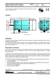
Ultrasonic transit time method<br />
The sensors A and B alternate as sender and receiver. With a voltage impulse a piezo-ceramic oscillator is excited.<br />
The ultrasonic impulse spreads out through the medium to be measured.<br />
The opposite site receives the impulse, converts it into an electric signal and analyzes it. A sound wave spreads<br />
out faster in the direction of the flow than against it. The <strong>RISONIC</strong> <strong>modular</strong> measures the transit time tAB and<br />
tBA. The transit time difference (tAB – tBA) of the two ultrasonic waveforms is directly proportional to the mean<br />
path velocity of the medium. From the mean path velocity in conjunction with the pipe geometry the flow can be<br />
determined.<br />
One-path measuring<br />
arrangement<br />
Sensor B<br />
Multi-path measuring<br />
arrangement<br />
Sensor A<br />
Multi-path measuring<br />
arrangement with crossed paths<br />
Under difficult hydraulic conditions a multi-path measuring arrangement can improve the measuring accuracy.<br />
Flow
Specifi cations<br />
Measuring accuracy Up to 0.5% of the measured value display (depending on the number<br />
of measuring paths, hydraulic conditions and the geometric parameters,<br />
such as path angle, path length, and their accuracy at the<br />
measuring point).<br />
Max. number of measuring paths 16<br />
Max. number of ultrasonic modules 4<br />
Number of measuring paths<br />
1 to 4 measuring paths in a multitude of different path arrangements<br />
per ultrasonic module<br />
Max. number of measuring points 4<br />
Pipe diameter 0.3 to 20m (with a path angle of 45°)<br />
Channel width 0.75 to 100 m (with a path angle of 45°)<br />
Flow speed ±20 m/s<br />
Ultrasonic module to sensor distance max. 300 m with 1 MHz sensors<br />
max. 500 m with 500 kHz sensors<br />
max. 1,000 m with 200 kHz sensors<br />
Controller module interfaces - LAN1: Ethernet 10/100 BaseT, USB 1.1 host, Compact Flash card<br />
- COM1: RS232, COM2: RS485, COM3: RS485<br />
- Status relay<br />
Ultrasonic module interfaces - 1 analog output, 1 analog input (4 … 20 mA)<br />
- 4 relay outputs<br />
Power supply 24 VDC (19.2 … 30 V)<br />
Power consumption Controller module: < 10 W<br />
Ultrasonic module: < 5 W<br />
Sleep Mode: < 0.5 W<br />
Overvoltage protection Integrated<br />
Safety class IP 20 on DIN rail<br />
IP 65 in fi eld unit<br />
Operating temperature range -20 to +70 °C<br />
Storage temperature -40 to +85 °C<br />
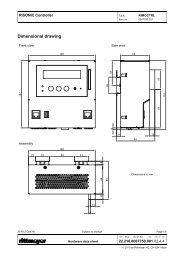
Device dimensions (H, W, D) Controller module: 147 x 146 x 64 mm<br />
Ultrasonic module: 184 x 147 x 52 mm<br />
Weight Controller module: approx. 1.1 kg<br />
Ultrasonic module: approx. 1.3 kg<br />
Installation options - Attached to DIN rail TS 35 in the control cabinet<br />
- Built into fi eld unit IP65<br />
Factors impacting the measuring accuracy:<br />
• Method to determine the transit times and differential transit times<br />
• Accuracy of the geometric data of the measuring arrangement<br />
• Integration method to calculate the fl ow based on path velocity and geometric data<br />
Contamination factors<br />
Contamination (typically quartz sand) in the water dampens the ultrasonic impulse, and, in extreme cases,<br />
makes a valid measurement impossible. The damping factor depends on the ultrasonic frequency, temperature,<br />
and particle properties. The <strong>RISONIC</strong> <strong>modular</strong> is equipped with an automatic amplifi cation control to be able<br />
to react to contamination in the water.<br />
Changes in the water composition can be recognized by monitoring the ultrasonic waveforms. Projection tools<br />
developed by <strong>Rittmeyer</strong> enable range estimates, provided that the water composition is known.
Engineering<br />
Effi cient tools and methods<br />
For the applicable measuring arrangement the following customer-specific and plant-specific factors are decisive:<br />
- Pipe geometry incl. obstructions<br />
- Measuring purpose<br />
- Measuring accuracy requirements<br />
Rules of thumb for calming sections (left-to-right fl ow) for a 1-path measurement and 1% accuracy.<br />
Flow velocity<br />
8.4<br />
7.8<br />
7.2<br />
6.6<br />
6.0<br />
Q<br />
Reduction<br />
y<br />
Measuring<br />
Two 90° elbow connectors on two levels<br />
In a fi rst step the most ideal installation site under the given conditions is determined. Then, in consideration of<br />
the above-mentioned factors, the measuring arrangement and orientation is confi gured. Multi-path measuring<br />
arrangements can have shorter calming sections.<br />
Subsequently, a suitable integration method for calculating the fl ow is selected based on the hydraulic<br />
conditions. These methods provide the sensor positions and the weighting of the individual measuring paths.<br />
Depending on the severity of the hydraulic conditions and the accuracy requirements, a variety of integration<br />
methods is available.<br />
Intuitive idealization of a<br />
(turbulent) v profi le<br />
v(y)<br />
90° elbow or tee connector Two 90° elbow connectors on one level<br />
Q<br />
Partially opened valve Pumps<br />
Idealized turbulent v profi le Simulated v profi le under most<br />
diffi cult hydraulic conditions<br />
y<br />
Integration method<br />
For pipes (round): Gauss-Jacobi OWICS (Optimal Weighted OWISS (Optimal Weighted<br />
Integration for Circular Sections) Integration for Simulated Sections)<br />
For pipes (rectangular): Gauss-Legendre OWIRS (Optimal Weighted<br />
Integration for Rectangular Sections)<br />
For extremely severe hydraulic conditions <strong>Rittmeyer</strong> provides CFD (Computational Fluid Dynamics) simulation<br />
services. The CFD simulation supports the selection of an optimal installation site, the orientation of the measuring<br />
paths and the integration. Furthermore, from the simulation the measuring accuracy can be estimated.<br />
v(y)<br />
Q<br />
y<br />
v(y)
Installation/commissioning<br />
Field-proven<br />
Other important prerequisites for fi rst rate fl ow measurements are the professional installation of the sensors at<br />
the theoretically defi ned positions, the professional determination of the cross-sectional area of the pipe at the<br />
measuring point, and measuring the exact positions of the installed sensors.<br />
Determining the sensor positions<br />
Measuring method with theodolite<br />
Drilling the sensor holes<br />
Do-it-yourself sensor installation<br />
For the sensor installation performed by<br />
the customer <strong>Rittmeyer</strong> provides a wide<br />
range of helpful marking and installation<br />
tools.<br />
Precision installation<br />
In order to meet the highest accuracy demands<br />
<strong>Rittmeyer</strong> recommends a precision installation<br />
performed by our experienced staff. To determine<br />
the geometric dimensions at the measuring<br />
point <strong>Rittmeyer</strong> uses a theodolite with integrated<br />
interferometer and laser pointer attachment for<br />
distance measurements.<br />
Scope of services<br />
- Determining the pipe cross-sectional areas<br />
- Determining the installation sites<br />
for the sensors<br />
- Sensor installation<br />
- Re-measuring the installed sensors<br />
- Sensor wiring<br />
- Defi ning safety measures against excess<br />
pressure and mechanical damage<br />
- Parameter confi guration of<br />
the measuring device<br />
- Commissioning<br />
- Testing<br />
- Customer training<br />
- Maintenance
Networked, international, performance-oriented<br />
<strong>Rittmeyer</strong><br />
A subsidiary of the<br />
BRUGG group.<br />
SWITZERLAND (Headquarters)<br />
<strong>Rittmeyer</strong> AG<br />
Inwilerriedstrasse 57<br />
Box 464<br />
CH-6341 Baar<br />
Phone: +41 41 767 10 00<br />
Fax: +41 41 767 10 70<br />
Email: info@rittmeyer.com<br />
Subsidiaries in<br />
Germany<br />
Austria<br />
Italy<br />
Spain<br />
France<br />
Croatia<br />
Slovakia<br />
Czech Republic<br />
<strong>Rittmeyer</strong> develops, manufactures<br />
and installs instrumentation and<br />
process control system solutions<br />
for the water and energy sector.<br />
Founded in 1904, <strong>Rittmeyer</strong> has<br />
commissioned more than 20,000<br />
installations to date. With 8 subsidiaries,<br />
a sales and representative<br />
offi ce and agencies in over 25<br />
countries we are active worldwide.<br />
Thanks to state-of-the-art technology,<br />
world class expertise and<br />
highest quality we provide our<br />
customers with reliable, precise<br />
and tailored solutions.<br />
Sales office in<br />
the US<br />
Representative office in<br />
Singapore<br />
Contact:<br />
22.040.0005000.001.01.4.4<br />
change. to<br />
www.rittmeyer.com Subject<br />
201001. Article number: 0082528.E01<br />
Printed in Switzerland.