MPC Data sheet - Rittmeyer
MPC Data sheet - Rittmeyer
MPC Data sheet - Rittmeyer

You also want an ePaper? Increase the reach of your titles
YUMPU automatically turns print PDFs into web optimized ePapers that Google loves.
Submersible Pressure Transmitter 4-20mA/RS485 5/6-wire <strong>MPC</strong> Type: <strong>MPC</strong>xxxxxxxx<br />
for level measurement Order No.: see Table 1 / Page 4<br />
Features<br />
• Four wire system<br />
• Piezoresistive measuring element<br />
• Output signal 4-20 mA and RS-485<br />
• Analogue output adjustable within 1 : 4 of the<br />
original measuring range<br />
• RS-485 interface with Modbus RTU protocol<br />
• Conformity error ≤ ±0.1 % FS,<br />
option ≤ ±0.05 % FS<br />
• Standard DIN measuring ranges from<br />
0 … 100 mbar up to 0 … 25 bar or selection of<br />
measuring ranges in mWC or psi<br />
• Temperature compensation within<br />
-10°C ... +50°C [+14°F … +122°F]<br />
• Temperature output<br />
• Optional overvoltage (lightning) protection<br />
according to EN 61000-4-5<br />
• Compact and robust<br />
Specifications<br />
Picture<br />
Unless otherwise stated, all specifications are at supply voltage 24 V DC, R L = 100 Ω and 25°C [77°F]<br />
operating temperature.<br />
Measuring Range Independent Technical <strong>Data</strong><br />
Type 4-wire current transmitter<br />
Analog output signal, pressure 4 … 20 mA<br />
Resolution 12 bit (< 0.025 % FS)<br />
Digital output signal (pressure and temperature) RS-485 Modbus RTU, 9600 bps<br />
Protocol details see <strong>Data</strong> Sheet SW 21.220.1560205.001<br />
Analog output signal, temperature 4 … 20 mA<br />
Measuring range -10°C ... +50°C [+14°F ... +122°F]<br />
Resolution 0.1°C [0.18°F]<br />
Accuracy of temperature measurement ≤ ±1°C [±1.8°F] in entire temperature measuring range<br />
Interface for adjustment RS-485 Modbus RTU, 9600 bps<br />
Protocol details see <strong>Data</strong> Sheet SW 21.220.1560205.001<br />
Output 0% adjustability -5% of original FS ... +105% of original FS<br />
Output 100% adjustability -5% of original FS ... +105% of original FS<br />
Difference (0% - 100%) adjustability ≥ 25% of original FS and ≥ 50 mbar [0.725 psi]<br />
Damping adjustability ~ 33 ms (default), 100 ms, 1 s, 10 s<br />
= 30 Hz (default), 10 Hz, 1 Hz, 0.1 Hz cut-off frequency<br />
200801 PJ/Ges/Pen Subject to change Seite 1/8<br />
DG DKap Stamm-Bez. Var Ind F Sp<br />
<strong>Data</strong> Sheet Hardware 21.210.1560205.001.03.4.4<br />
© 2008 by <strong>Rittmeyer</strong> AG, CH-6341 Baar
Submersible Pressure Transmitter 4-20mA/RS485 5/6-wire <strong>MPC</strong> <strong>MPC</strong>xxxxxxxx<br />
Supply voltage DC 9 ... 30 V<br />
Reverse polarity protection Integrated, standard<br />
Overvoltage protection (lightning protection) Option<br />
Supply voltage influence < 0.1 % FS<br />
Current consumption<br />
(requirement without 4 ... 20 mA outputs,<br />
without RS-485 load) ≤ 20 mA<br />
Maximum voltage housing / supply 500 V<br />
Permitted load see paragraph "Cable Lengths"<br />
Load influence < 0.1 % FS<br />
Protection class IP68 (~NEMA 6P)<br />
Medium temperature range -5°C ... +50°C [+23°F ... +122°F]<br />
Temperature compensation range -10°C ... +50°C [+14°F ... +122°F]<br />
Storage temperature range -10°C ... +50°C [+14°F ... +122°F]<br />
Acid resistance pH5 ... pH9<br />
Weight Approx. 200 g [0.441 lb] without overvoltage protection<br />
Approx. 280 g [0.617 lb] with overvoltage protection<br />
plus approx. 260 g [0.573 lb] with weight extension<br />
Measuring cell, membrane, housing Stainless steel 1.4435 (316L)<br />
Seals Viton<br />
Cable Choice of PE / PUR / FEP cable with integrated<br />
pressure equalising pipe<br />
Outer diameter 6 mm [0.24"] PE / PUR; 5 mm [0.2"] FEP<br />
Leads 0.22 mm 2 [AWG 24], Cu wire 7 x 0.20 tinned<br />
Resistance ≤ 82.9 mΩ/m [25.3 mΩ/ft] (one conductor)<br />
Minimum cable bending radius 100 mm [4"]<br />
Tensile load < 400 N [90 lbf] (PE / PUR cables)<br />
< 15 N [3.4 lbf] (FEP cables)<br />
Tensile strength > 500 N [112 lbf]<br />
Pressure equalising pipe diameter Ø 1.4 / 0.8 mm [0.055" / 0.03"] PE / PUR;<br />
Ø 1.1 / 0.6 mm [0.04" / 0.02"] FEP<br />
PE cable (foodstuffs approved / drinking water)<br />
Permitted environmental temperature -20°C … +70°C [-4°F ... +158°F]<br />
Weight Approx. 41 g/m [0.44 oz/ft]<br />
PUR cable (mechanically robust)<br />
Permitted environmental temperature -20°C … +95°C [-4°F ... +203°F]<br />
Weight Approx. 45 g/m [0.48 oz/ft]<br />
FEP cable (high temperature range)<br />
Permitted environmental temperature -40°C … +90°C [-40°F ... +194°F]<br />
Weight Approx. 55 g/m [0.59 oz/ft]<br />
Electromagnetic Compatibility<br />
Emissions<br />
Basic specification emissions EN 61000-6-3<br />
Emissions class B EN 55022<br />
Immunity<br />
Basic specification noise immunity EN 61000-6-2<br />
Electrostatic discharge EN 61000-4-2 (4 kV contact, 8 kV air)<br />
Radiated electromagnetic field EN 61000-4-3 (10 V/m, 80 ... 1000 MHz, 80% AM 1 kHz)<br />
Radiated electromagnetic field (GSM) EN 61000-4-3 (10 V/m, 950 MHz, 200 Hz on/off)<br />
200801 PJ/Ges/Pen Subject to change Page 2/8<br />
DG DKap Stamm-Bez. Var Ind F Sp<br />
<strong>Data</strong> Sheet Hardware 21.210.1560205.001.03.4.4<br />
© 2008 by <strong>Rittmeyer</strong> AG, CH-6341 Baar
Submersible Pressure Transmitter 4-20mA/RS485 5/6-wire <strong>MPC</strong> <strong>MPC</strong>xxxxxxxx<br />
Fast transients (burst) EN 61000-4-4 (2 kV)<br />
Conducted electromagnetic interference EN 61000-4-6 (10 V/m, 0,15 ... 80 MHz, 80% AM 1 kHz)<br />
Impulse voltage (surge) EN 61000-4-5 (10 kA 8/20µs)<br />
[only with the option overvoltage (lightning) protection]<br />
Quality Tests<br />
The transmitters fulfil the requirements for noise immunity and emissions of the EMC directive<br />
89/336/EEC.<br />
Measurement Range Dependent Technical <strong>Data</strong><br />
Pressure ranges < 0.2 bar<br />
[2.9 psi]<br />
≥ 0.2 ... 1 bar<br />
[2.9...14.5 psi]<br />
≥ 1 ... 25 bar<br />
[14.5...362.6 psi]<br />
Overload 3 bar [43.5 psi] 3 bar [43.5 psi] 3 x FS<br />
Bursting pressure > 200 bar [2900 psi] > 200 bar [2900 psi] > 200 bar [2900 psi]<br />
Conformity error incl. hysteresis<br />
and repeatability<br />
-5°C ... +50°C [+23°F...+122°F] ≤ ±0.2 % FS ≤ ±0.1 % FS ≤ ±0.1 % FS<br />
Option for pressure ranges ≥ 1 bar --- --- ≤ ±0.05 % FS<br />
Temperature error zero / span<br />
-10°C ... +50°C typ.<br />
[+14°F...+122°F] max.<br />
≤ ±100 ppm FS/°C<br />
≤ ±150 ppm FS/°C<br />
≤ ±60 ppm FS/°C<br />
≤ ±100 ppm FS/°C<br />
≤ ±60 ppm FS/°C<br />
≤ ±100 ppm FS/°C<br />
Long term drift typ. ≤ 0.2 % FS/a ≤ 0.2 % FS/a ≤ 0.1 % FS/a<br />
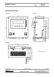
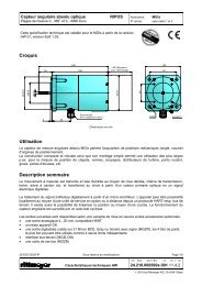
Dimensions [mm]<br />
Ø6 [0.24"] PE-/PUR-cable<br />
Ø5 [0.2"] FEP-cable<br />
Ø6 [0.24"] PE-/PUR-cable<br />
Ø5 [0.2"] FEP-cable<br />
Transmitter reference point<br />
A<br />
Ø24<br />
[Ø0.95"]<br />
Transmitter reference point<br />
B<br />
Ø24<br />
[0.95"]<br />
11<br />
[0.43"]<br />
7<br />
[0.28"]<br />
Closed version (standard):<br />
A = 157 mm [6.2"] without overvoltage protection<br />
A = 258 mm [10.2"] with overvoltage protection<br />
Plus 87 mm [3.4"] with weight extension<br />
Open version:<br />
B = 153 mm [6.0"] without overvoltage protection<br />
B = 254 mm [10.0"] with overvoltage protection<br />
Plus 87 mm [3.4"] with weight extension<br />
200801 PJ/Ges/Pen Subject to change Page 3/8<br />
DG DKap Stamm-Bez. Var Ind F Sp<br />
<strong>Data</strong> Sheet Hardware 21.210.1560205.001.03.4.4<br />
© 2008 by <strong>Rittmeyer</strong> AG, CH-6341 Baar
Submersible Pressure Transmitter 4-20mA/RS485 5/6-wire <strong>MPC</strong> <strong>MPC</strong>xxxxxxxx<br />
Ordering Information<br />
Table 1:<br />
The precise designation for an article is derived from the combination of the individual option codes<br />
according to the table (with the BAAN configurator PCF or manually).<br />
<strong>MPC</strong><br />
PCF Order Number<br />
1/2 3 4 5 6 7 8 9 10 11 12 13 14 15 16<br />
Type<br />
<strong>MPC</strong> PC<br />
Pressure Type<br />
Relative 1<br />
Measuring Range<br />
0 ... 100 mbar = 0 ... 1.45 psi 0 0<br />
0 ... 160 mbar = 0 ... 2.32 psi 0 1<br />
0 ... 250 mbar = 0 ... 3.63 psi 0 2<br />
0 ... 400 mbar = 0 ... 5.8 psi 0 3<br />
0 ... 600 mbar = 0 ... 8.7 psi 0 4<br />
0 ... 1.0 bar = 0 ... 14.5 psi 0 5<br />
0 ... 1.6 bar = 0 ... 23.2 psi 0 6<br />
0 ... 2.5 bar = 0 ... 36.25 psi 0 7<br />
0 ... 4.0 bar = 0 ... 58 psi 0 8<br />
0 ... 6.0 bar = 0 ... 87 psi 0 9<br />
0 ... 10 bar = 0 ... 145 psi 1 0<br />
0 ... 16 bar = 0 ... 232 psi 1 1<br />
0 ... 25 bar = 0 ... 362.5 psi 1 2<br />
0 ... 1 mWC 6 0<br />
0 ... 2 mWC 6 1<br />
0 ... 5 mWC 6 2<br />
0 ... 10 mWC 6 3<br />
0 ... 20 mWC 6 4<br />
0 ... 50 mWC 6 5<br />
0 ... 1.5 psi 7 0<br />
0 ... 3.0 psi 7 1<br />
0 ... 7.5 psi 7 2<br />
0 ... 15 psi 7 3<br />
0 ... 30 psi 7 4<br />
0 ... 75 psi 7 5<br />
0 ... 150 psi 7 6<br />
0 ... 300 psi 7 7<br />
Special calibration (always > 0 ... 100 mbar) 9 9<br />
Version<br />
Closed, standard (membrane protected) 5 5<br />
Open 5 6<br />
Electrical Connection<br />
PE cable (foodstuffs approved) 1 3<br />
PUR cable (robust) 1 5<br />
FEP cable (large temperature range) 2 1<br />
Output Signal<br />
4 ... 20 mA P & T & RS-485 without overvoltage protection 6 5<br />
4 ... 20 mA P & T & RS-485 with overvoltage protection 6 6<br />
Accuracy<br />
±0.2 % FS, only for measuring ranges < 200 mbar 4<br />
±0.1 % FS, only for measuring ranges ≥ 200 mbar 2<br />
±0.05 % FS, only for measuring ranges ≥ 1 bar 6<br />
Temperature Range<br />
Compensated -10°C ... +50°C (medium -5 ... 50°C) 4<br />
Cable Length<br />
Cable length in metres (always ≥ 001) x x x<br />
200801 PJ/Ges/Pen Subject to change Page 4/8<br />
DG DKap Stamm-Bez. Var Ind F Sp<br />
<strong>Data</strong> Sheet Hardware 21.210.1560205.001.03.4.4<br />
© 2008 by <strong>Rittmeyer</strong> AG, CH-6341 Baar
Submersible Pressure Transmitter 4-20mA/RS485 5/6-wire <strong>MPC</strong> <strong>MPC</strong>xxxxxxxx<br />
Parameterisation<br />
With the aid of the programming kit MPPKIT available as an accessory, the software of the submersible<br />
transmitter can be parameterised with a PC (see also <strong>Data</strong> Sheet 21.210.0066900.001 and Operating<br />
Instructions 21.810.0066900.001).<br />
• Range selection for output current 4 ... 20 mA<br />
With the range selection 4 ... 20 mA, the 4 mA and 20 mA current values can be assigned to measured<br />
values other than the standard 0% and 100% of the nominal measuring range. (Typically with 4 mA a<br />
value from the range -5% ... +25% of the nominal measuring range, with 20 mA, a value from the range<br />
+25% ... +105% of the nominal measuring range.) In this way, a sub-range or even a negative pressure<br />
can be measured. The difference ∆ between the minimum and maximum must amount to at least 25% of<br />
the nominal measuring range and be at least 50 mbar.<br />
Inverted control can be achieved by exchanging the values for 4 mA and 20 mA.<br />
The ranges of adjustability are presented graphically in the following illustrations.<br />
Non-inverted Control: Inverted Control:<br />
Output current I out<br />
20 mA<br />
Adjustability<br />
range<br />
(only rel.)<br />
4 mA<br />
∆ ≥ 25%FS ≥ 0,05bar<br />
-5% 20% 80% 105%<br />
0%<br />
Nominal<br />
Working Range (FS)<br />
100%<br />
Standard<br />
Example<br />
Adjustability<br />
range<br />
(rel. or abs.)<br />
Measured<br />
value p<br />
Output current I out<br />
20 mA<br />
Adjustability<br />
range<br />
(only rel.)<br />
4 mA<br />
∆ ≥ 25%FS ≥ 0,05bar<br />
-5% 20% 80% 105%<br />
0%<br />
Nominal<br />
Working Range (FS)<br />
100%<br />
Example 1<br />
Example 2<br />
Adjustability<br />
range<br />
(rel. or abs.)<br />
Measured<br />
value p<br />
• Programmable Damping of the Current Output<br />
The analog output can be damped with a low pass filter of the 1st order. The adjustability enables values<br />
between ~ 33 ms (default) and 10 s.<br />
Note: During commissioning, damping is preferably left at the minimum value.<br />
• Recalibrating the transmitter (calibration 0 % or 100 %) enables compensation of the drift which<br />
inevitably occurs with resistive pressure transducers. The zero drift alone or the combination of zero drift<br />
and slope change can be compensated. In doing so, the original calibration of the transmitter is not lost<br />
and can be recalled as necessary.<br />
Setting range 0%: -5% … +5% of nominal measuring range (FS)<br />
Setting range 100%: 95% ... 105% of nominal measuring range (FS)<br />
Standard Settings<br />
The transmitters have the following standard parameterisation:<br />
• Current range: 4 mA ... 20 mA<br />
• Measurement start: 4 mA = 0% of nominal measuring range (FS)<br />
• Measurement end: 20 mA = 100% of nominal measuring range (FS)<br />
• Damping: ~ 33 ms<br />
200801 PJ/Ges/Pen Subject to change Page 5/8<br />
DG DKap Stamm-Bez. Var Ind F Sp<br />
<strong>Data</strong> Sheet Hardware 21.210.1560205.001.03.4.4<br />
© 2008 by <strong>Rittmeyer</strong> AG, CH-6341 Baar
Submersible Pressure Transmitter 4-20mA/RS485 5/6-wire <strong>MPC</strong> <strong>MPC</strong>xxxxxxxx<br />
Block Diagram / Electrical Connections<br />
P<br />
T<br />
I<br />
I<br />
+Vin<br />
Pout<br />
Tout<br />
RS-485<br />
A<br />
B<br />
RS-485<br />
GND<br />
Cable Length<br />
A A<br />
U B<br />
+Vin ↔ white<br />
Pout ↔ brown<br />
Tout ↔ pink<br />
A ↔ green<br />
B ↔ grey<br />
GND ↔ yellow<br />
Several marginal conditions also contribute to determining the maximum cable length. Unlike 2-conductor<br />
transmitters, the maximum permitted resistance in the probe circuit can not be determined from one single<br />
formula. Depending on the application and mounting as well as the use of only digital or only analog or both<br />
output types, some of the criteria listed below have to be taken into consideration:<br />
Minimum Supply Voltage<br />
If the conductor resistance is concentrated and designated as RW, the following simplified replacement<br />
diagram results for the static consideration of a probe (IS is the supply current without load, RR is the RS-485<br />
terminal resistance, Uo is the amplitude of the signal voltage at the output of the RS-485 driver):<br />
P<br />
T<br />
I<br />
I<br />
RS-485<br />
+Vin<br />
Pout<br />
Tout<br />
A<br />
B<br />
GND<br />
U o<br />
R W<br />
R W<br />
R W<br />
R W<br />
R W<br />
R W<br />
I S + I R + I M1 + I M2<br />
I M1<br />
I M2<br />
I R<br />
I S + I R<br />
R R<br />
R M2<br />
A A<br />
R M1<br />
The following is valid as the result of voltage drop at the supply lines:<br />
⎛ U ⎞ o<br />
U B ≥ 2RW ⎜ I S + + RW<br />
+ in<br />
2RW<br />
R ⎟<br />
⎝ + R ⎠<br />
( I M 1max<br />
+ I M 2 max ) V min<br />
At the same time however, the supply voltage must not be greater than the maximum supply voltage (30 V).<br />
200801 PJ/Ges/Pen Subject to change Page 6/8<br />
U B<br />
DG DKap Stamm-Bez. Var Ind F Sp<br />
<strong>Data</strong> Sheet Hardware 21.210.1560205.001.03.4.4<br />
© 2008 by <strong>Rittmeyer</strong> AG, CH-6341 Baar
Submersible Pressure Transmitter 4-20mA/RS485 5/6-wire <strong>MPC</strong> <strong>MPC</strong>xxxxxxxx<br />
Maximum 4 ... 20 mA Load<br />
In order that the output stages in the transmitter can still work properly, the load resistance (RW + RMi) must<br />
not be greater than:<br />
2RW = U [V] – 6V/0.02A 1 kOhm max.<br />
RS-485 Length Limit<br />
The total length of an RS-485 bus must not be greater than 1.2 km [0.75 mile]. This length is the addition of<br />
the lengths of all RS-485 segments that are directly connected to one another.<br />
To cover greater distances, RS-485 / RS-485 repeaters (such as Westermo RD-48 or Phoenix PSM-ME-<br />
RS485 / RS485-P) have to be installed.<br />
RS-485 Common Mode Limit<br />
The current flowing through the ground (GND) conductor (supply for the probes, bus current IR as well as<br />
possible additional current components) causes a voltage drop between the probe GND and the GND of the<br />
receiver (the same as an PLC or a processing unit or an RS-485/RS-485 repeater) which, from the view of<br />
the RS-485, presents a common mode voltage. With RS-485, this voltage must never be greater than ±7 V.<br />
Analog Output Negative Limit<br />
The current flowing through the ground (GND) conductor (supply for the probes, bus current IR as well as<br />
possible additional current components) causes a voltage drop between the probe GND and the GND of the<br />
20 mA current connection which, from the view of the probe, pulls the analog output into the negative. Even<br />
in the worst case (analog output = 4 mA), the output potential must not be less than 5 V below the probe<br />
GND.<br />
Own Weight<br />
If the cable is suspended as self-supporting, its own weight and the permitted tensile strength can present a<br />
length limit.<br />
Note<br />
• If the submersible transmitter is used at temperatures, where the medium can freeze over a longer time,<br />
we recommend the version with open protective cap. The version with open protective cap is<br />
recommended also in dirty water.<br />
• In order to prevent destruction, the membrane must not be touched.<br />
• The cable must not be tight bend or flat squeezed (because of the integrated pressure equalising pipe).<br />
• Moisture must not be allowed to enter the pressure equalisation pipe. It is recommended that a junction<br />
box with dehumidifying agent is used.<br />
• For applications in the field with extension cables having a cable length ≥ 5 m [16 ft] or inside a building<br />
with cable lengths ≥ 100 m [330 ft], a transmitter with the overvoltage protection option and an external<br />
overvoltage protection ASBG.48 or an junction box MPZAD2U.002 (at other end of the cable) must be<br />
used.<br />
• The cable shield must be connected to a good ground potential.<br />
200801 PJ/Ges/Pen Subject to change Page 7/8<br />
DG DKap Stamm-Bez. Var Ind F Sp<br />
<strong>Data</strong> Sheet Hardware 21.210.1560205.001.03.4.4<br />
© 2008 by <strong>Rittmeyer</strong> AG, CH-6341 Baar
Submersible Pressure Transmitter 4-20mA/RS485 5/6-wire <strong>MPC</strong> <strong>MPC</strong>xxxxxxxx<br />
• In order to compensate the long term drift an annual zero point alignment is recommended.<br />
• If the accuracy option 0.05% FS is used, the RS-485 interface with 10'000 steps resolution (1 step =<br />
0.01%) should be used, because the analogue output has only 4096 steps resolution (1 step = 0.024%).<br />
• RS-485 Modbus networks with cable lengths > 100 m [330 ft] must be projected carefully (net topology,<br />
terminating resistor, type of cable, overvoltage protection).<br />
• Conversion table for units of measurement used for pressure<br />
(Value in new unit) = coefficient x (value in old unit)<br />
Coefficient New Unit<br />
Old Unit Pa = 1 N/m 2 bar mWC ftWC mmHg (Torr) psi kp/cm 2 = at<br />
Pa = 1 N/m 2 1 10 -5 1.02 x 10 -4 3.35 7.5 x 10 -3 1.45 x 10 -4 1.02 x 10 -5<br />
bar 10 5 1 10.2 33.5 750 14.5 1.02<br />
mWC 9.81 x 10 3 9.81 x 10 -2 1 3.28 73.6 1.42 0.1<br />
ftWC 2.99 x 10 3 2.99 x 10 -2 0.305 1 22.4 0.433 3.05 x 10 -2<br />
mmHg (Torr) 1.33 x 10 2 1.33 x 10 -3 1.36 x 10 -2 4.46 x 10 -2 1 1.93 x 10 -2 1.36 x 10 -3<br />
psi 6.89 x 10 3 6.89 x 10 -2 0.703 2.31 51.7 1 7.03 x 10 -2<br />
kp/cm 2 = at 9.81 x 10 4 0.981 10 32.8 736 14.2 1<br />
Example: 2 bar = ? psi:<br />
bar = "old unit", psi = "new unit", ⇒ "coefficient" = 14.5<br />
2 bar = 14.5 x 2 psi = 29 psi<br />
Accessories<br />
Abbreviation Order No.<br />
Programming Kit consisting of interface box and<br />
Programming Software under Windows 9x / ME / NT / 2000 / XP MPPKIT 0066900.001<br />
Extension cable 6-wire, shielded (L in metres) MPZVK6 04 60 106<br />
Junction box for submersible sensor IP65 (~NEMA 6) MPZAD.002 00 65 194.001<br />
Junction box for submersible sensor IP65 (~NEMA 6), 2 OVP MPZAD2U.002 00 65 192.001<br />
Overvoltage protection AC/DC 48V ASBG.48 00 32 721.003<br />
Suspension arrangement for submersible probe MPZHVT 00 65 717.001<br />
Protection tube 2 m [6.6 ft] for pressure sensor (still water) MPZSRR 00 65 720.001<br />
Protection tube 2 m [6.6 ft] for pressure sensor (flowing water) MPZSRF 00 65 721.001<br />
Protection tube extension 2 m [6.6 ft] for MPZSRR, MPZSRF MPZSRV 00 65 722.001<br />
Sensor box for submersible probe MPZFK 00 65 543.001<br />
Protection tube for sensor cabinet MPZSRU 00 65 549.001<br />
Dehumidifier insert complete MPZDES 00 65 191.001<br />
200801 PJ/Ges/Pen Subject to change Page 8/8<br />
DG DKap Stamm-Bez. Var Ind F Sp<br />
<strong>Data</strong> Sheet Hardware 21.210.1560205.001.03.4.4<br />
© 2008 by <strong>Rittmeyer</strong> AG, CH-6341 Baar