250 Series DIN Rail and Wall Mounted Relays - Crompton Western ...
250 Series DIN Rail and Wall Mounted Relays - Crompton Western ...
250 Series DIN Rail and Wall Mounted Relays - Crompton Western ...

You also want an ePaper? Increase the reach of your titles
YUMPU automatically turns print PDFs into web optimized ePapers that Google loves.
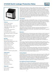
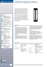
<strong>250</strong> <strong>Series</strong> <strong>DIN</strong> <strong>Rail</strong> <strong>and</strong> <strong>Wall</strong> <strong>Mounted</strong> <strong>Relays</strong><br />
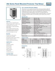
A.C. Current with Adjustable Time Delay<br />
<strong>250</strong> series A.C. current protectors provide continuous surveillance of the monitored<br />
circuit. When the current moves outside the setpoint limit, the relay operates. The<br />
protector can be used to monitor over <strong>and</strong> under current conditions, load detection,<br />
<strong>and</strong> for monitoring electric heating systems. An illuminated LED indicates when the<br />
relay is energized. For 3 phase systems, the sequence of connection is not important.<br />
Features<br />
Single <strong>and</strong> 3 phase options<br />
Adjustable setpoint<br />
Adjustable time delay<br />
Internal differential<br />
LED trip indication<br />
Double pole relay contacts<br />
Automatic reset<br />
Benefits<br />
Ideal for any electrical load detection<br />
Over <strong>and</strong> under current monitoring<br />
Suitable for electric heating systems<br />
Ensures load current is within generator<br />
capacity<br />
Detects broken drive belts on machinery<br />
Nuisance tripping avoidance<br />
Customized options<br />
Applications<br />
Marine panels<br />
Switchgear<br />
Distribution systems<br />
Generator sets<br />
Control panels<br />
Process control<br />
Motor protection<br />
Transformers<br />
Overload protection<br />
Approvals<br />
UL, CSA, BV <strong>and</strong> ABS<br />
Operation<br />
A.C. current protectors provide continuous surveillance of the monitored circuit.<br />
These products offer user adjustable trip point (setpoint) <strong>and</strong> time delay settings. The<br />
setpoint adjustment range is between 40% <strong>and</strong> 120% of the nominal current. Input<br />
currents can be via current transformers or direct up to 10A. An internal differential<br />
setting of 1% reduces nuisance tripping if the measured signal is noisy or unstable.<br />
When the measured current moves outside the setpoint limit, the relay will operate,<br />
giving an alarm or initiation signal. An adjustable time delay is provided to prevent<br />
the relay from tripping for a predetermined period to prevent nuisance tripping. The<br />
units draw their operating power from a separate auxiliary supply input. Single<br />
phase <strong>and</strong> three phase products are available. Three phase products monitor the<br />
current level for each phase, <strong>and</strong> are not phase sequence sensitive. Combined units<br />
offer under <strong>and</strong> over current trips in one compact unit. Single function units are also<br />
available.<br />
Over Current Models<br />
When the monitored current exceeds the setpoint, the relay will energize <strong>and</strong> the red<br />
LED will illuminate to indicate the trip condition. The relay will automatically reset<br />
once the monitored current falls below the setpoint minus the differential. When<br />
reset, the LED will extinguish <strong>and</strong> the relay de-energizes.<br />
Under Current Models<br />
When the monitored current falls below the setpoint, the relay will de-energize <strong>and</strong><br />
the red LED will extinguish to indicate the trip condition. The relay will automatically<br />
reset once the monitored current rises above the setpoint plus the differential. When<br />
reset, the LED will illuminate <strong>and</strong> the relay energizes.<br />
Options<br />
<strong>250</strong> series protector relays offer various customized options to suit individual<br />
requirements. Please consult factory.<br />
• Adjustment ranges - different adjustment ranges are possible for the setpoint<br />
<strong>and</strong> differential controls.<br />
• Relay operation - st<strong>and</strong>ard models are fail safe, but the relays can be customized<br />
to energize or de-energize on trip.<br />
Product Codes<br />
Relay Protection ANSI No. Catalog No.<br />
Single phase Under current 40-120% 37 252-PAU<br />
Single phase Over current 40-120% 51 252-PAO<br />
Single phase Under <strong>and</strong> over current 37/51 253-PAD<br />
3 phase 3 or 4 wire Under current 40-120% 37 253-PAV<br />
3 phase 3 or 4 wire Over current 40-120% 51 253-PAP<br />
Specify system voltage, system current, frequency <strong>and</strong> required options at time of<br />
ordering.<br />
20
<strong>250</strong> <strong>Series</strong> <strong>DIN</strong> <strong>Rail</strong> <strong>and</strong> <strong>Wall</strong> <strong>Mounted</strong> <strong>Relays</strong><br />
Connections<br />
252-PAU<br />
252-PAO<br />
253-PAD<br />
Input<br />
Relay<br />
Contact Set 1 Contact Set 2<br />
Input<br />
Under Relay<br />
Contact Set 1<br />
Supply<br />
Over Relay<br />
Contact Set 1<br />
Specification – AC Current with Adjustable Time Delay<br />
Nominal Input Current<br />
1A or 5A from CT secondary.<br />
0.2A to 10A available on request<br />
Nominal Frequency<br />
50, 60 or 400Hz<br />
Input Current Burden<br />
0.5VA per phase<br />
Overload<br />
2 x rating continuously, 10 x rating for 3 seconds<br />
Set Point Repeatability<br />
>0.5% of full span<br />
Differential (Hysteresis)<br />
Preset at 1%. Values 1% to 10% available on request<br />
Trip Level Adjustment<br />
40 to 120%. Customized adjustment available<br />
Time Delay Adjustable<br />
0 to 10 seconds<br />
AC Auxiliary Supply Voltage 100V, 110V, 120V, 208V, 220V, 240V, 480V, ±20%<br />
DC Auxiliary Supply Voltage 12V, 24V, 48V, 110V or 125V, ±15%. Max ripple 15%<br />
Auxiliary Voltage Burden<br />
4VA (max)<br />
Output Relay<br />
Double pole change over<br />
Relay Contact Rating<br />
AC: 240V 5A, non inductive<br />
DC: 24V, 5A resistive<br />
Relay Mechanical Life<br />
0.2 million operations at rated loads<br />
Relay Reset<br />
Automatic<br />
Operating Temperature<br />
0°C to +60°C (0°C to +40°C for UL models)<br />
Storage Temperature -20°C to + 70°C<br />
Temperature Co-efficient 0.05% per °C<br />
Interference Immunity<br />
Electrical stress surge withst<strong>and</strong> <strong>and</strong> nonfunction<br />
to ANSI/IEEE C37 90a<br />
Enclosure Style<br />
<strong>DIN</strong> rail with wall mounting facility<br />
Material<br />
Flame retardant polycarbonate/ABS<br />
Enclosure Integrity<br />
IP50<br />
Compliant With EMC, LVD, Safety St<strong>and</strong>ard IEC 414<br />
UL File No: E113067 recognized up to 600V<br />
CSA File No: LR52592 up to 300V<br />
BV File No: 2650H-07427-AO-PRSO BV<br />
ABS File No: 93-LD 17806-X<br />
Model 252 Dimensions<br />
55mm (2.2") wide x 70mm (2.8") high<br />
x 112mm (4.4") deep<br />
Model 253 Dimensions<br />
75mm (2.9") wide x 70mm (2.8") high<br />
x 112mm (4.4") deep<br />
Weight<br />
Model 252: 0.4Kg approx.<br />
Model 253: 0.6Kg approx.<br />
Dimensions<br />
Model 252<br />
55 (2.2)<br />
112 (4.4)<br />
55 (2.2)<br />
2 HOLES<br />
Ø 4.1<br />
253-PAP<br />
253-PAV<br />
Input<br />
1<br />
Under Relay<br />
Contact Set 2<br />
Input<br />
2<br />
Supply<br />
Over Relay<br />
Contact Set 2<br />
Input<br />
3<br />
70 (2.8)<br />
35 (1.37)<br />
RELEASE CLIP<br />
35 (1.37)<br />
17.5 (0.68)<br />
35 (1.37)<br />
12<br />
(0.5)<br />
15.5<br />
(0.6)<br />
Model 253<br />
75 (2.9)<br />
112.5 (4.4)<br />
60 (2.4)<br />
35 (1.37)<br />
70 (2.8)<br />
50 (1.96)<br />
60 (2.36)<br />
Relay<br />
Contact Set 1<br />
Supply<br />
Relay<br />
Contact Set 2<br />
RELEASE CLIP<br />
2 FIXING HOLE<br />
'A' TO SUIT M4<br />
2 FIXING HOLE<br />
'A' TO SUIT M4<br />
21
<strong>250</strong> <strong>Series</strong> <strong>DIN</strong> <strong>Rail</strong> <strong>and</strong> <strong>Wall</strong> <strong>Mounted</strong> <strong>Relays</strong><br />
A.C. Voltage with Adjustable Time Delay<br />
The A.C. voltage protectors provide continuous surveillance of the monitored circuit.<br />
When the measured voltage moves outside the setpoint limit, the relay will operate<br />
after the selected time delay, giving an alarm or initiation signal. <strong>Relays</strong> normally<br />
energize on overvolts <strong>and</strong> de-energize on undervolts. An illuminated LED indicates<br />
when the relay is energized.<br />
Features<br />
Adjustable setpoint<br />
Adjustable time delay<br />
Internal differential<br />
LED trip indication<br />
Double pole relay contacts<br />
Automatic reset<br />
Benefits<br />
Over <strong>and</strong> under voltage monitoring<br />
Close voltage control<br />
Start st<strong>and</strong>by generators<br />
Operation of mains failure units<br />
Switching st<strong>and</strong>by supplies<br />
Protecting computer supplies<br />
Monitors genset AVR <strong>and</strong> excitation<br />
systems<br />
Nuisance tripping avoidance<br />
Customized options<br />
Applications<br />
Switchgear<br />
Distribution systems<br />
Generator sets<br />
Control panels<br />
Process control<br />
Motor protection<br />
Transformers<br />
Overload protection<br />
Approvals<br />
UL <strong>and</strong> CSA<br />
Operation<br />
A.C. voltage protectors offer user adjustable trip point (setpoint) <strong>and</strong> time delay<br />
settings. The setpoint adjustment range is 25%, operating between 75% <strong>and</strong> 100% of<br />
the nominal supply for under voltage units, <strong>and</strong> between 100% <strong>and</strong> 125% for the<br />
over voltage units. The time delay setting adjustment range is typically 0 to 10<br />
seconds, although longer delays are available. As soon as the monitored signal<br />
moves outside of the setpoint limit, the time delay is activated, after which a trip will<br />
occur. The time delay prevents the relay from tripping for a predetermined period to<br />
prevent nuisance tripping.<br />
The products also feature an internal differential (hysteresis) setting of 1% to reduce<br />
nuisance tripping if the measured signal is noisy or unstable. The units draw their<br />
operating power from the measuring inputs, although a separate auxiliary supply<br />
input option is available on some models. Single phase <strong>and</strong> three phase products are<br />
available, three phase products monitor the voltage level for each phase, <strong>and</strong> are not<br />
phase sequence sensitive.<br />
Over Voltage Models<br />
When the monitored voltage exceeds the setpoint, the time delay is started. When<br />
the time has elapsed, the relay will energize <strong>and</strong> the red LED will illuminate to<br />
indicate the trip condition. The relay will automatically reset once the monitored<br />
voltage falls below the setpoint minus the differential. When reset, the LED will<br />
extinguish <strong>and</strong> the relay de energizes. The time delay is not active when resetting.<br />
Under Voltage Models<br />
When the monitored voltage falls below the setpoint, the time delay is started. When<br />
the time has elapsed, the relay will de-energize <strong>and</strong> the red LED will extinguish to<br />
indicate the trip condition. The relay will automatically reset once the monitored<br />
voltage rises above the setpoint plus the differential. When reset, the LED will<br />
illuminate <strong>and</strong> the relay energizes. The time delay is not active when resetting.<br />
Options<br />
<strong>250</strong> series protector relays offer various customized options to suit individual<br />
requirements.<br />
Please consult factory.<br />
• Adjustment ranges - different adjustment ranges are possible for the setpoint <strong>and</strong><br />
differential controls.<br />
• Separate auxiliary supply - sometimes required to maintain a time delay or<br />
energized relay when the monitored signal fails.<br />
• Differential - internally fixed value between 1% <strong>and</strong> 15%.<br />
• Relay operation - st<strong>and</strong>ard models are fail safe, but the relays can be customized<br />
to energize or de-energize on trip.<br />
Product Codes<br />
Relay Protection ANSI No. Catalog No.<br />
Single phase Under voltage 75-100% 27 252-PVZ<br />
Single phase Over voltage 100-125% 59 252-PVH<br />
3 phase 3 wire Under voltage 75-100% 27 252-PVJ<br />
3 phase 3 wire Over voltage 100-125% 59 252-PVC<br />
3 phase 4 wire Under voltage 75-100% 27 252-PVX<br />
3 phase 4 wire Over voltage 100-125% 59 252-PVS<br />
Specify system voltage, frequency <strong>and</strong> required options at time of ordering.<br />
22
<strong>250</strong> <strong>Series</strong> <strong>DIN</strong> <strong>Rail</strong> <strong>and</strong> <strong>Wall</strong> <strong>Mounted</strong> <strong>Relays</strong><br />
Connections<br />
252-PVZ<br />
252-PVH<br />
252-PVX<br />
252-PVS<br />
252-PVC<br />
252-PVJ<br />
Relay<br />
Contact Set 1 Contact Set 2<br />
Input<br />
Aux supply<br />
when required<br />
Relay<br />
Contact Set 1 Contact Set 2<br />
Specification – AC Voltage with Adjustable Time Delay<br />
Nominal Voltage<br />
100V, 110V, 208V, 240V, 277V, 400V, 415V, 440V<br />
or 480V<br />
System Frequency<br />
45/65Hz or 360/440Hz<br />
Voltage Burden<br />
0.3VA<br />
Overload<br />
1.2 x rating continuously, 1.5 x rating for<br />
10 x seconds<br />
Set Point Repeatability<br />
> 0.5% of full span<br />
Differential (Hysteresis) Preset at 1%.<br />
Other values 1% to 10% to order<br />
Trip Level Adjustment Under Voltage: 75 to 100%<br />
Over Voltage: 100 to 125% of nominal input voltage<br />
Time Delay<br />
Adjustable up to 10 seconds<br />
AC Auxiliary Supply Voltage 100V, 110V, 120V, 208V, 220V, 240V, 480V, ±20%<br />
DC Auxiliary Supply Voltage 12V, 24V, 48V, 110V or 125V, ±15%. Max ripple 15%<br />
Auxiliary Voltage Burden<br />
4VA (max)<br />
Output Relay<br />
Double pole change over<br />
Relay Contact Rating<br />
AC: 240V 5A, non inductive<br />
DC: 24V, 5A resistive<br />
Relay Mechanical Life<br />
0.2 million operations at rated loads<br />
Relay Reset<br />
Automatic<br />
Operating Temperature<br />
0°C to +60°C (0°C to +40°C for UL models)<br />
Storage Temperature -20°C to + 70°C<br />
Temperature Co-efficient 0.05% per °C<br />
Interference Immunity<br />
Electrical stress surge withst<strong>and</strong> <strong>and</strong> nonfunction<br />
to ANSI/IEEE C37 90a<br />
Enclosure Style<br />
<strong>DIN</strong> rail with wall mounting facility<br />
Material<br />
Flame retardant polycarbonate/ABS<br />
Enclosure Integrity<br />
IP50<br />
Compliant With EMC, LVD, Safety St<strong>and</strong>ard IEC 414<br />
UL File No: E113067 recognized up to 600V<br />
CSA File No: LR52592 up to 300V<br />
Dimensions<br />
55mm (2.2") wide x 70mm (2.8") high x<br />
112mm (4.4") deep<br />
Weight<br />
0.4Kg approx.<br />
Dimensions<br />
Model 252<br />
55 (2.2)<br />
112 (4.4)<br />
55 (2.2)<br />
2 HOLES<br />
Ø 4.1<br />
12<br />
(0.5)<br />
Input<br />
Aux supply<br />
when required<br />
Note: The neutral connection is always<br />
used on 4 wire systems.<br />
70 (2.8)<br />
35 (1.37)<br />
35 (1.37)<br />
17.5 (0.68)<br />
35 (1.37)<br />
15.5<br />
(0.6)<br />
RELEASE CLIP<br />
23
<strong>250</strong> <strong>Series</strong> <strong>DIN</strong> <strong>Rail</strong> <strong>and</strong> <strong>Wall</strong> <strong>Mounted</strong> <strong>Relays</strong><br />
A.C. Voltage with Adjustable Differential<br />
The A.C. voltage protectors provide continuous surveillance of the monitored circuit.<br />
When the measured voltage moves outside the setpoint limit, the relay will operate<br />
giving an alarm or initiation signal. The protector can be used for under <strong>and</strong> over<br />
voltage detection, start st<strong>and</strong>by generators, operation of mains failure units, <strong>and</strong><br />
switching st<strong>and</strong>by supplies. An illuminated LED indicates when the relay is<br />
energized. The 3 phase, 3 or 4 wire models, protect each phase independently.<br />
Features<br />
Single <strong>and</strong> 3 phase models<br />
Adjustable setpoint<br />
Adjustable differential<br />
Internal time delay<br />
LED trip indication<br />
Double pole relay contacts<br />
Automatic reset<br />
Benefits<br />
Over <strong>and</strong> under voltage monitoring<br />
Start st<strong>and</strong>by generators<br />
Operation of mains failure units<br />
Switching st<strong>and</strong>by supplies<br />
Monitors genset AVR <strong>and</strong> excitation<br />
systems<br />
Nuisance tripping avoidance<br />
Customized options<br />
Applications<br />
Marine panels<br />
Switchgear<br />
Distribution systems<br />
Generator sets<br />
Control panels<br />
Process control<br />
Motor protection<br />
Transformers<br />
Overload protection<br />
Approvals<br />
UL , CSA , BV <strong>and</strong> ABS<br />
Operation<br />
A.C. voltage protectors offer user adjustable trip point (setpoint) <strong>and</strong> differential<br />
(hysteresis) settings. The setpoint adjustment range is 25%, operating between 75%<br />
<strong>and</strong> 100% of the nominal supply for under voltage units, <strong>and</strong> between 100% <strong>and</strong><br />
125% for the over voltage units. The differential setting adjustment range is 1% to<br />
15%, <strong>and</strong> it can be used to reduce nuisance tripping if the measured signal is noisy<br />
or unstable. When the measured voltage moves outside the setpoint limit, the relay<br />
will operate, giving an alarm or initiation signal.<br />
As soon as the monitored signal moves outside of the setpoint limit, a trip will occur.<br />
A fixed time delay is available as a factory option, preventing the relay from tripping<br />
for a predetermined period to prevent nuisance tripping. The units draw their<br />
operating power from the measuring inputs, although a separate auxiliary supply<br />
input option is available on some models. Three phase products monitor the voltage<br />
level for each phase, <strong>and</strong> are not phase sequence sensitive. Combined units offer<br />
under <strong>and</strong> over voltage trips in one compact unit. Single function units are<br />
also available.<br />
Over Voltage Models<br />
When the monitored voltage exceeds the setpoint, the relay will energize <strong>and</strong> the red<br />
LED will illuminate to indicate the trip condition. The relay will automatically reset<br />
once the monitored voltage falls below the setpoint minus the differential. When<br />
reset, the LED will extinguish <strong>and</strong> the relay de-energizes.<br />
Under Voltage Models<br />
When the monitored voltage falls below the setpoint, the relay will de-energize <strong>and</strong><br />
the red LED will extinguish to indicate the trip condition. The relay will automatically<br />
reset once the monitored voltage rises above the setpoint plus the differential. When<br />
reset, the LED will illuminate <strong>and</strong> the relay energizes.<br />
Options<br />
<strong>250</strong> series protector relays offer various customized options to suit individual<br />
requirements. Please consult factory.<br />
• Time delay - internal fixed time delay before a trip occurs.<br />
• Separate auxiliary supply - sometimes required to maintain a time delay or<br />
energized relay when the monitored signal fails.<br />
• Adjustment ranges - different adjustment ranges are possible for the setpoint <strong>and</strong><br />
differential controls.<br />
• Relay operation - st<strong>and</strong>ard models are fail safe, but the relays can be customized<br />
to energize or de-energize on trip.<br />
Product Codes<br />
Relay Protection ANSI No. Catalog No.<br />
Single phase Under voltage 75-100% 27 252-PVU<br />
Single phase Over voltage 100-125% 59 252-PVO<br />
Single phase Under <strong>and</strong> over voltage 27/59 253-PVB<br />
3 phase 3 wire Under voltage 75-100% 27 252-PVK<br />
3 phase 3 wire Over voltage 100-125% 59 252-PVA<br />
3 phase 3 wire Under <strong>and</strong> over voltage 27/59 253-PVM<br />
3 phase 4 wire Under voltage 75-100% 27 252-PVV<br />
3 phase 4 wire Over voltage 100-125% 59 252-PVP<br />
3 phase 4 wire Under <strong>and</strong> over voltage 27/59 253-PVE<br />
Specify system voltage, frequency, <strong>and</strong> required options at time of ordering.<br />
24
<strong>250</strong> <strong>Series</strong> <strong>DIN</strong> <strong>Rail</strong> <strong>and</strong> <strong>Wall</strong> <strong>Mounted</strong> <strong>Relays</strong><br />
Connections<br />
252-PVU<br />
252-PVO<br />
252-PVV<br />
252-PVP<br />
252-PVK<br />
252-PVA<br />
253-PVB<br />
Relay<br />
Contact Set 1 Contact Set 2<br />
3 Phase Input<br />
L<br />
N<br />
Single Phase<br />
Input<br />
Under Relay<br />
Contact Set 1<br />
Over Relay<br />
Contact Set 1<br />
Aux<br />
supply<br />
when<br />
required<br />
Specification – AC Voltage with Adjustable Differential<br />
Nominal Voltage 100V, 110V, 120V, 208V, 220V, 270V, 280V,<br />
400V, 415V or 440V<br />
System Frequency<br />
45/65Hz or 360/440Hz<br />
Voltage Burden<br />
0.3VA approx<br />
Overload<br />
1.2 x rating continuously, 1.5 x rating for<br />
10 x seconds<br />
Set Point Repeatability<br />
>0.5% of full span<br />
Differential (Hysteresis) Adjustable range 1 to 15%<br />
Trip Level Adjustment Under Voltage: 75 to 100%<br />
Over Voltage: 100 to 125% of nominal input voltage<br />
Time Delay<br />
Factory preset up to 30 seconds<br />
AC Auxiliary Supply Voltage 100V, 110V, 120V, 208V, 220V, 240V, 480V, ±20%<br />
DC Auxiliary Supply Voltage 12V, 24V, 48V, 110V or 125V, ±15%. Max ripple 15%<br />
Auxiliary Voltage Burden<br />
4VA (max)<br />
Output Relay<br />
Double pole change over<br />
Relay Contact Rating<br />
AC: 240V 5A, non inductive<br />
DC: 24V, 5A resistive<br />
Relay Mechanical Life<br />
0.2 million operations at rated loads<br />
Relay Reset<br />
Automatic<br />
Operating Temperature<br />
0°C to +60°C (0°C to +40°C for UL models)<br />
Storage Temperature -20°C to + 70°C<br />
Temperature Co-efficient 0.05% per °C<br />
Interference Immunity<br />
Electrical stress surge withst<strong>and</strong> <strong>and</strong> nonfunction<br />
to ANSI/IEEE C37 90a<br />
Enclosure Style<br />
<strong>DIN</strong> rail with wall mounting facility<br />
Material<br />
Flame retardant polycarbonate/ABS<br />
Enclosure Integrity<br />
IP50<br />
Compliant With EMC, LVD, Safety St<strong>and</strong>ard IEC 414<br />
UL File No: E113067 recognized up to 600V<br />
CSA File No: LR52592 up to 300V<br />
BV File No: 2650H-07427-AO PRSO BV (Model 253 only)<br />
ABS File No: 93-LD 17806-X (Model 253 only)<br />
Model 252 Dimensions<br />
55mm (2.2") wide x 70mm (2.8") high<br />
x 112mm (4.4") deep<br />
Model 253 Dimensions<br />
75mm (2.9") wide x 70mm (2.8") high<br />
x 112mm (4.4") deep<br />
Weight<br />
Model 252: 0.4Kg approx. Model 253: 0.6Kg approx<br />
Dimensions<br />
253-PVE<br />
253-PVM<br />
Input<br />
Under Relay<br />
Contact Set 2<br />
Input<br />
Over Relay<br />
Contact Set 2<br />
Model 252<br />
70 (2.8)<br />
55 (2.2)<br />
35 (1.37)<br />
112 (4.4)<br />
35 (1.37)<br />
17.5 (0.68)<br />
55 (2.2)<br />
35 (1.37)<br />
2 HOLES<br />
Ø 4.1<br />
12<br />
(0.5)<br />
15.5<br />
(0.6)<br />
RELEASE CLIP<br />
Model 253<br />
75 (2.9)<br />
112.5 (4.4)<br />
60 (2.4)<br />
Input<br />
35 (1.37)<br />
70 (2.8)<br />
50 (1.96)<br />
60 (2.36)<br />
Note: The neutral connection is always<br />
used on 4 wire systems.<br />
RELEASE CLIP<br />
2 FIXING HOLE<br />
'A' TO SUIT M4<br />
2 FIXING HOLE<br />
'A' TO SUIT M4<br />
25
<strong>250</strong> <strong>Series</strong> <strong>DIN</strong> <strong>Rail</strong> <strong>and</strong> <strong>Wall</strong> <strong>Mounted</strong> <strong>Relays</strong><br />
Frequency<br />
<strong>Crompton</strong> frequency protectors give continuous surveillance of the monitored circuit.<br />
When the frequency moves outside the set point limit the relay will operate giving an<br />
alarm, control or tripping signal. An illuminated LED indicates when the relay is<br />
energized. Since speed is proportional to the frequency, this protector can be used to<br />
monitor over <strong>and</strong> underspeed, <strong>and</strong> to protect mains supplies, computer supplies, <strong>and</strong><br />
st<strong>and</strong>by supplies for Industrial, Hospital or Marine use.<br />
Features<br />
Adjustable setpoint<br />
Adjustable differential<br />
LED trip indication<br />
Double pole relay contacts<br />
Automatic reset<br />
Benefits<br />
Over <strong>and</strong> under frequency monitoring<br />
Over <strong>and</strong> underspeed monitoring<br />
Start st<strong>and</strong>by generators<br />
Operation of mains failure units<br />
Switching st<strong>and</strong>by supplies<br />
Protection of control gear<br />
Nuisance tripping avoidance<br />
Customized options<br />
Applications<br />
Marine panels<br />
Switchgear<br />
Distribution systems<br />
Generator sets<br />
Control panels<br />
Process control<br />
Motor protection<br />
Transformers<br />
Overload protection<br />
Operation<br />
Frequency protectors offer user adjustable frequency trip point (setpoint) <strong>and</strong><br />
differential (hysteresis) settings. The setpoint adjustment range is centred around the<br />
nominal 50Hz, 60Hz or 400Hz system frequency. The differential setting adjustment<br />
can be used to reduce nuisance tripping if the measured signal is noisy or unstable.<br />
When the measured frequency moves outside the setpoint limit, the relay will<br />
operate, giving an alarm or initiation signal. As soon as the monitored frequency<br />
moves outside of the setpoint limit, a trip will occur. The units draw their operating<br />
power from the measuring inputs. Combined units offer under <strong>and</strong> over frequency<br />
trips in one compact unit. Single function units are also available.<br />
Over Frequency Models<br />
When the monitored frequency exceeds the setpoint, the relay will energize <strong>and</strong> the<br />
red LED will illuminate to indicate the trip condition. The relay will automatically<br />
reset once the monitored frequency falls below the setpoint minus the differential.<br />
When reset, the LED will extinguish <strong>and</strong> the relay de-energizes.<br />
Under Frequency Models<br />
When the monitored frequency falls below the setpoint, the relay will de-energize<br />
<strong>and</strong> the red LED will extinguish to indicate the trip condition. The relay will<br />
automatically reset once the monitored frequency rises above the setpoint plus the<br />
differential. When reset, the LED will illuminate <strong>and</strong> the relay energizes.<br />
Options<br />
<strong>250</strong> series protector relays offer various customized options to suit individual<br />
requirements. Please consult factory.<br />
• Adjustment ranges - different adjustment ranges are possible for the setpoint <strong>and</strong><br />
differential controls.<br />
• Time delay - internal fixed time delay before a trip occurs.<br />
• Relay operation - st<strong>and</strong>ard models are fail safe, but the relays can be customized<br />
to energize or de-energize on trip.<br />
Product Codes<br />
Relay Protection ANSI No. Catalog No.<br />
Single phase Under frequency 81U 252-PHU<br />
Single phase Over frequency 81O 252-PHO<br />
Single phase Under <strong>and</strong> over frequency 81O/U 253-PHD<br />
Specify system voltage, frequency <strong>and</strong> required options at time of ordering.<br />
Approvals<br />
UL, CSA, BV <strong>and</strong> ABS<br />
26
<strong>250</strong> <strong>Series</strong> <strong>DIN</strong> <strong>Rail</strong> <strong>and</strong> <strong>Wall</strong> <strong>Mounted</strong> <strong>Relays</strong><br />
Connections<br />
252-PHU<br />
252-PHO<br />
253-PHD<br />
Output Relay<br />
Contact Set 1 Contact Set 2<br />
Input<br />
Under Relay<br />
Contact Set 1<br />
Over Relay<br />
Contact Set 1<br />
Specification – Frequency<br />
Nominal Voltage 100V, 110V, 120V, 208V, 220V, 230V, 240V,<br />
277V, 380V, 400V, 415V, 440V or 480V ± 20%<br />
System Frequency<br />
40/60Hz, 50/70Hz or 360/440Hz<br />
Voltage Burden<br />
3VA<br />
Overloads<br />
1.2 x rating continuously, 1.5 x rating for<br />
10 x seconds<br />
Set Point Repeatability<br />
>0.5% of full span<br />
Differential (Hysteresis)<br />
40/60Hz, 50/70Hz: Adjustable 0.1 to 3.0Hz<br />
360/440Hz: Adjustable 10 to 30Hz<br />
Output Relay<br />
Double pole change over<br />
Relay Contact Rating<br />
AC: 240V 5A, non inductive<br />
DC: 24V, 5A resistive<br />
Relay Mechanical Life<br />
0.2 million operations at rated loads<br />
Relay Reset<br />
Automatic<br />
Operating Temperature<br />
0°C to +60°C (0°C to +40°C for UL models)<br />
Storage Temperature -20°C to + 70°C<br />
Temperature Co-efficient 0.05% per °C<br />
Interference Immunity<br />
Electrical stress surge withst<strong>and</strong> <strong>and</strong><br />
non-function to ANSI/IEEE C37 90a<br />
Enclosure Style<br />
<strong>DIN</strong> rail with wall mounting facility<br />
Material<br />
Flame retardant polycarbonate/ABS<br />
Enclosure Integrity<br />
IP50<br />
Compliant With EMC, LVD, Safety St<strong>and</strong>ard IEC 414<br />
UL File No: E113067 recognized up to 600V<br />
CSA File No: LR52592 up to 400Hz 300V<br />
BV File No: 2650H-07427-AO PRSO BV<br />
ABS File No: 93-LD 17806-X<br />
Model 252 Dimensions<br />
55mm (2.2") wide x 70mm (2.8") high<br />
x 112mm (4.4") deep<br />
Model 253 Dimensions<br />
75mm (2.9") wide x 70mm (2.8") high<br />
x 112mm (4.4") deep<br />
Weight<br />
Model 252: 0.4Kg approx.<br />
Model 253: 0.6Kg approx<br />
Dimensions<br />
Model 252<br />
55 (2.2)<br />
112 (4.4)<br />
55 (2.2)<br />
2 HOLES<br />
Ø 4.1<br />
12<br />
(0.5)<br />
Under Relay<br />
Contact Set 2<br />
Input<br />
Over Relay<br />
Contact Set 2<br />
70 (2.8)<br />
35 (1.37)<br />
35 (1.37)<br />
17.5 (0.68)<br />
35 (1.37)<br />
15.5<br />
(0.6)<br />
RELEASE CLIP<br />
Model 253<br />
75 (2.9)<br />
112.5 (4.4)<br />
60 (2.4)<br />
35 (1.37)<br />
70 (2.8)<br />
50 (1.96)<br />
60 (2.36)<br />
RELEASE CLIP<br />
2 FIXING HOLE<br />
'A' TO SUIT M4<br />
2 FIXING HOLE<br />
'A' TO SUIT M4<br />
27
<strong>250</strong> <strong>Series</strong> <strong>DIN</strong> <strong>Rail</strong> <strong>and</strong> <strong>Wall</strong> <strong>Mounted</strong> <strong>Relays</strong><br />
Combined Under/Over Voltage <strong>and</strong> Frequency<br />
The <strong>250</strong> series combined voltage & frequency protectors provide continuous<br />
surveillance of the monitored circuit. When the voltage or frequency moves outside<br />
the set point limit the respective relay will operate giving an alarm, control or<br />
tripping signal. An illuminated LED indicates when the relay is energized. This<br />
protector can be used to protect against over <strong>and</strong> underspeed <strong>and</strong> over <strong>and</strong><br />
under voltage.<br />
Features<br />
Adjustable setpoint<br />
Adjustable time delay<br />
Internal differential<br />
LED trip indication<br />
Double pole relay contacts<br />
Automatic reset<br />
Benefits<br />
Over <strong>and</strong> under voltage monitoring<br />
Over <strong>and</strong> underspeed monitoring<br />
Start st<strong>and</strong>by generators<br />
Operation of mains failure units<br />
Switching st<strong>and</strong>by supplies<br />
Monitors genset AVR <strong>and</strong> excitation<br />
systems<br />
Nuisance tripping avoidance<br />
Customized options<br />
Applications<br />
Switchgear<br />
Distribution systems<br />
Generator sets<br />
Control panels<br />
Process control<br />
Motor protection<br />
Transformers<br />
Overload protection<br />
Operation<br />
Combined voltage <strong>and</strong> frequency protectors provide the most popular relay functions<br />
in one convenient package. The products offer user adjustable trip point (setpoint)<br />
for voltage <strong>and</strong> frequency, plus adjustable time delay settings. The setpoint<br />
adjustment range is 25%, operating between 75% <strong>and</strong> 100% of the nominal supply<br />
for under voltage, <strong>and</strong> between 100% <strong>and</strong> 125% for over voltage. The frequency<br />
setpoint adjustment range is centred around the nominal 50Hz, 60Hz or 400Hz<br />
system frequency. The time delay setting adjustment range is typically 0 to 10<br />
seconds, although longer delays are available.<br />
As soon as the monitored signal moves outside of the setpoint limit, the time delay<br />
is activated, after which a trip will occur. The time delay prevents the relay from<br />
tripping for predetermined period to prevent nuisance tripping. The products also<br />
feature an internal differential (hysteresis) setting of 1% to reduce nuisance tripping if<br />
the measured signal is noisy or unstable. The product is available for single phase<br />
systems only, <strong>and</strong> draws its operating power from the measuring input.<br />
Over Voltage <strong>and</strong> Frequency<br />
When the monitored value exceeds the setpoint <strong>and</strong> the time delay has elapsed, the<br />
relay will energize <strong>and</strong> the red LED will illuminate to indicate the trip condition.<br />
Under Voltage <strong>and</strong> Frequency<br />
The relay will de-energize after the time delay has elapsed, <strong>and</strong> the red LED will<br />
extinguish to indicate the trip condition.<br />
Options<br />
<strong>250</strong> series protector relays offer various customized options to suit individual<br />
requirements. Please consult factory.<br />
• Adjustment ranges - different adjustment ranges are possible for the setpoint <strong>and</strong><br />
time delay controls.<br />
• Differential - internally fixed value between 1% <strong>and</strong> 15%.<br />
• Relay operation - st<strong>and</strong>ard models are fail safe, but the relays can be customized<br />
to energize or de-energize on trip.<br />
Product Codes<br />
Relay Protection ANSI No. Catalog No.<br />
Single phase Over <strong>and</strong> under voltage, 27/59, 256-PHV<br />
over <strong>and</strong> under frequency 81O/U<br />
Specify system voltage, frequency <strong>and</strong> required options at time of ordering.<br />
Approvals<br />
UL recognized<br />
28
<strong>250</strong> <strong>Series</strong> <strong>DIN</strong> <strong>Rail</strong> <strong>and</strong> <strong>Wall</strong> <strong>Mounted</strong> <strong>Relays</strong><br />
Dimensions<br />
Model 256<br />
2 FIXING HOLE<br />
'A' TO SUIT M4<br />
112.5 (4.4)<br />
150 (5.9)<br />
135 (5.3)<br />
35 (1.37)<br />
50 (1.96)<br />
60 (2.36)<br />
2 FIXING HOLE<br />
'A' TO SUIT M4<br />
Specification – Combined Under/Over <strong>and</strong> Frequency<br />
Nominal Voltage 100V, 110V, 120V, 208V, 220V, 270V, 280V,<br />
400V, 415V or 440V<br />
System Frequency<br />
40/60Hz, 50/70Hz or 360/440Hz<br />
Frequency Differential<br />
Preset at 0.1Hz (10Hz for 400Hz unit)<br />
Voltage Burden<br />
3VA<br />
Overloads<br />
1.2 x rating continuously, 1.5 x rating for<br />
10 x seconds<br />
Set Point Repeatability<br />
>0.5% of full span<br />
Differential (Hysteresis) Fixed internally at 1%<br />
Trip Level Adjustment Over voltage: 100 to 125%<br />
Under Voltage: 75 to 100% of nominal input voltage<br />
Time Delay<br />
Adjustable 1 to 30 seconds<br />
Output Relay<br />
4 independent double pole change over<br />
Relay Contact Rating<br />
AC: 240V 5A, non inductive<br />
DC: 24V, 5A resistive<br />
Relay Mechanical Life<br />
0.2 million operations at rated loads<br />
Relay Reset<br />
Automatic<br />
Operating Temperature<br />
0°C to +60°C (0°C to +40°C for UL models)<br />
Storage Temperature -20°C to + 70°C<br />
Temperature Co-efficient 0.05% per °C<br />
Interference Immunity<br />
Electrical stress surge withst<strong>and</strong> <strong>and</strong> nonfunction<br />
to ANSI/IEEE C37 90a<br />
Enclosure Style<br />
<strong>DIN</strong> rail with wall mounting facility<br />
Material<br />
Flame retardant polycarbonate/ABS<br />
Enclosure Integrity<br />
IP50<br />
Compliant With EMC, LVD, Safety St<strong>and</strong>ard IEC 414<br />
UL File No: E113067 recognized up to 600V<br />
Dimensions<br />
150mm (5.9") wide x 70mm (2.8") high<br />
x 112mm (4.4") deep<br />
Weight<br />
1.0Kg approx<br />
Connections<br />
256-PHV<br />
Under Voltage Relay<br />
Contact Set 1<br />
Over Voltage Relay<br />
Contact Set 1<br />
Under Frequency Relay<br />
Contact Set 1<br />
Over Frequency Relay<br />
Contact Set 1<br />
70 (2.8)<br />
RELEASE CLIP<br />
Input<br />
Contact Set 2 Contact Set 2<br />
Contact Set 2 Contact Set 2<br />
29
<strong>250</strong> <strong>Series</strong> <strong>DIN</strong> <strong>Rail</strong> <strong>and</strong> <strong>Wall</strong> <strong>Mounted</strong> <strong>Relays</strong><br />
Phase Sequence <strong>and</strong> Phase Failure<br />
The <strong>Crompton</strong> phase sequence <strong>and</strong> phase failure protector relays are designed to<br />
monitor the correct phase rotation or sequence of three phase, 3 or 4 wire supply<br />
systems <strong>and</strong> provide protection against incorrect phase sequence, loss of one phase,<br />
<strong>and</strong> under voltage.<br />
Features<br />
Three phase, 3 or 4 wire<br />
LED trip indication<br />
Double pole relay contacts<br />
Automatic reset<br />
Benefits<br />
Monitoring of correct phase rotation<br />
Protection against incorrect phase<br />
sequence <strong>and</strong> loss of phase<br />
Under voltage monitoring<br />
Prevents reverse rotation of motor<br />
driven equipment<br />
Ensures correct engine rotation<br />
Protects portable electrical equipment<br />
Applications<br />
Marine panels<br />
Switchgear<br />
Distribution systems<br />
Generator sets<br />
Control panels<br />
Process control<br />
Motor protection<br />
Transformers<br />
Overload protection<br />
Operation<br />
Rotating machines are particularly vulnerable to incorrect phase sequence. Three<br />
phase motors can rotate in the wrong direction, potentially leading to physical<br />
damage or the risk of injury to personnel, yet voltage <strong>and</strong> current readings may<br />
appear normal. If one phase is lost because of a blown fuse, electric motors can<br />
continue to operate (single phasing) which can result in severe electrical or<br />
mechanical damage. For permanent installations, this relay should be used to<br />
monitor the incoming supply, protecting all equipment against incorrect connection<br />
at initial installation or after maintenance work. Rotating machines that cannot<br />
tolerate reverse rotation or pose significant risk to personnel under this condition<br />
should be individually protected with this relay. The possibility of incorrect supply<br />
connection is much more likely in portable equipment or marine applications.<br />
The phase sequence <strong>and</strong> phase failure protectors continuously monitor the three<br />
phase supply. With the correct phase sequence applied, the front panel LED will<br />
illuminate <strong>and</strong> the output relay will be energized. An incorrect sequence or missing<br />
phase will de-energize the relay, <strong>and</strong> the LED will be extinguished. If the supply<br />
drops below 85% of its nominal voltage, this condition will also cause a trip.<br />
Note: If one phase is lost due to a blown fuse, some loads can re-generate the<br />
missing voltage. This relay can be used as a phase failure relay providing the<br />
regenerated voltage in the open phase is less than 70% of the nominal supply<br />
voltage. If there is the possibility of a higher regenerated voltage, the phase balance<br />
relay 252-PSF should be used.<br />
Product Codes<br />
Relay Protection ANSI No. Catalog No.<br />
3 phase 3 or 4 wire Phase sequence, 47 252-PVR<br />
under voltage 85%<br />
Specify system voltage, frequency <strong>and</strong> required options at time of ordering.<br />
Approvals<br />
UL, CSA, BV <strong>and</strong> ABS<br />
30
<strong>250</strong> <strong>Series</strong> <strong>DIN</strong> <strong>Rail</strong> <strong>and</strong> <strong>Wall</strong> <strong>Mounted</strong> <strong>Relays</strong><br />
Connections<br />
252-PVR<br />
Relay<br />
Contact Set 1 Contact Set 2<br />
Input<br />
Note: No neutral connection is required.<br />
Specification – Phase Sequence <strong>and</strong> Phase Failure<br />
Nominal Voltage 110V, 120V, 208V, 220V, 230V, 240V, 277V,<br />
380V, 400V, 415V, 440V or 480V<br />
Nominal Frequency<br />
50, 60 or 400Hz<br />
Voltage Burden<br />
3VA approx.<br />
Overload<br />
1.2 x rating continuously, 1.5 x rating for 10 x<br />
seconds to symmetric<br />
Trip Level Adjustment<br />
Preset at 85% of nominal<br />
Auxiliary Voltage Burden<br />
4VA (max)<br />
Output Relay<br />
Double pole change over<br />
Relay Contact Rating<br />
AC: 240V 5A, non inductive<br />
DC: 24V, 5A resistive<br />
Relay Mechanical Life<br />
0.2 million operations at rated loads<br />
Relay Reset<br />
Automatic<br />
Operating Temperature<br />
0°C to +60°C (0°C to +40°C for UL models)<br />
Storage Temperature -20°C to + 70°C<br />
Temperature Co-efficient 0.05% per °C<br />
Interference Immunity<br />
Electrical stress surge withst<strong>and</strong> <strong>and</strong> nonfunction<br />
to ANSI/IEEE C37 90a<br />
Enclosure Style<br />
<strong>DIN</strong> rail with wall mounting facility<br />
Material<br />
Flame retardant polycarbonate/ABS<br />
Enclosure Integrity<br />
IP50<br />
Compliant With EMC, LVD, US Safety St<strong>and</strong>ard IEC 414<br />
UL File No: E113067 recognized up to 600V<br />
CSA File No: LR52592 up to 300V<br />
BV File No: 2650H-07427-AO PRSO BV<br />
ABS File No; 93-LD 17806-X<br />
Model 252 Dimensions<br />
55mm (2.2") wide x 70mm (2.8") high<br />
x 112mm (4.4") deep<br />
Weight<br />
0.4Kg approx.<br />
Dimensions<br />
Model 252<br />
55 (2.2)<br />
112 (4.4)<br />
55 (2.2)<br />
2 HOLES<br />
Ø 4.1<br />
12<br />
(0.5)<br />
70 (2.8)<br />
35 (1.37)<br />
35 (1.37)<br />
17.5 (0.68)<br />
35 (1.37)<br />
15.5<br />
(0.6)<br />
RELEASE CLIP<br />
31
<strong>250</strong> <strong>Series</strong> <strong>DIN</strong> <strong>Rail</strong> <strong>and</strong> <strong>Wall</strong> <strong>Mounted</strong> <strong>Relays</strong><br />
Phase Balance<br />
The <strong>250</strong> series phase balance protector module provides continuous surveillance of a<br />
3 phase, 3 or 4 wire system <strong>and</strong> monitors the correct phase rotation or sequence of<br />
three phase supply systems. The module protects against phase loss, reversal or<br />
sequence, phase unbalance, <strong>and</strong> system under voltage.<br />
Features<br />
Three phase, 3 or 4 wire<br />
Adjustable setpoint<br />
Adjustable time delay<br />
Internal differential<br />
LED trip indication<br />
Double pole relay contacts<br />
Automatic reset<br />
Benefits<br />
Monitoring of correct phase rotation<br />
Protects against phantom or<br />
regenerated phase voltage<br />
Protection against phase loss, reversal<br />
or sequence<br />
Under voltage <strong>and</strong> unbalanced voltage<br />
monitoring<br />
Prevents reverse rotation of motor<br />
driven equipment<br />
Ensures correct engine rotation<br />
Protects portable electrical equipment<br />
Nuisance tripping avoidance<br />
Operation<br />
Rotating machines are particularly vulnerable to incorrect phase sequence. Three<br />
phase motors can rotate in the wrong direction, potentially leading to physical<br />
damage or the risk of injury to personnel, yet voltage <strong>and</strong> current readings may<br />
appear normal. If one phase is lost because of a blown fuse, electric motors can<br />
continue to operate (single phasing) which can result in severe electrical or<br />
mechanical damage. This relay has the added advantage that it will detect the<br />
phantom or regenerated phase that can be caused by a single phase failure on some<br />
equipment or when running motors at low load levels.<br />
An unbalanced supply voltage can lead to temperature rises in motors. An unbalance<br />
voltage as little as 10% can increase operating temperature to150% of normal. For<br />
permanent installations, this relay should be used to monitor the incoming supply,<br />
protecting all equipment against incorrect connection at initial installation or after<br />
maintenance work. Rotating machines that cannot tolerate reverse rotation or pose<br />
significant risk to personnel under this condition should be individually protected<br />
with this relay. The possibility of incorrect supply connection is much more likely in<br />
portable equipment or marine applications.<br />
The protector continuously monitors the three phase supply. With the correct phase<br />
sequence applied <strong>and</strong> all three voltages balanced within the required limits, the front<br />
panel LED will illuminate <strong>and</strong> the output relay will be energized. An incorrect<br />
sequence, missing phase, out of balance or under voltage condition will de-energize<br />
the relay, <strong>and</strong> the LED will be extinguished.<br />
The setpoint control allows adjustment of the voltage matching between 5% <strong>and</strong><br />
15%. The time delay function operates only for the voltage unbalance condition. The<br />
delay can be used to prevent nuisance tripping due to short term unbalance<br />
situations. Incorrect phase rotation, a missing phase or an under voltage condition<br />
trip the relay immediately.<br />
Product Codes<br />
Relay Protection ANSI No. Catalog No.<br />
3 phase 3 or 4 wire Phase loss <strong>and</strong> 47 252-PSF<br />
unbalance 5 - 15%<br />
3 phase 3 or 4 wire Phase loss, unbalance 47/27 252-PSG<br />
<strong>and</strong> under voltage 5-15%<br />
Specify system voltage, frequency <strong>and</strong> required options at time of ordering.<br />
Applications<br />
Marine panels<br />
Switchgear<br />
Distribution systems<br />
Generator sets<br />
Control panels<br />
Process control<br />
Motor protection<br />
Transformers<br />
Overload protection<br />
Approvals<br />
UL, CSA, BV <strong>and</strong> ABS<br />
32
<strong>250</strong> <strong>Series</strong> <strong>DIN</strong> <strong>Rail</strong> <strong>and</strong> <strong>Wall</strong> <strong>Mounted</strong> <strong>Relays</strong><br />
Connections<br />
252-PSF<br />
252-PSG<br />
Relay<br />
Contact Set 1 Contact Set 2<br />
Input<br />
Note: Neutral connection not required<br />
Specification – Phase Balance<br />
Nominal Voltage 110V, 120V, 208V, 220V, 230V, 240V, 277V,<br />
380V, 400V, 415V, 440V or 480V<br />
System Frequency<br />
50 or 60Hz<br />
Voltage Burden<br />
3VA approx.<br />
Overload<br />
1.2 x rating continuously, 1.5 x rating for<br />
10 x seconds<br />
Set Point Repeatability<br />
>0.5% of full span<br />
Under Voltage Setpoint<br />
Preset at 15% of nominal voltage. Other values<br />
10 to 30% to order (Model 252-PSG only)<br />
Trip Level Adjustment Phase unbalance adjustable 5 to 15%<br />
Time Delay<br />
10 seconds as st<strong>and</strong>ard. Up to 30 seconds available<br />
Auxiliary Voltage Burden<br />
4VA (max)<br />
Output Relay<br />
Double pole change over<br />
Relay Contact Rating<br />
AC: 240V 5A, non inductive<br />
DC: 24V, 5A resistive<br />
Relay Mechanical Life<br />
0.2 million operations at rated loads<br />
Relay Reset<br />
Automatic<br />
Operating Temperature<br />
0°C to +60°C (0°C to +40°C for UL models)<br />
Storage Temperature -20°C to + 70°C<br />
Temperature Co-efficient 0.05% per °C<br />
Interference Immunity<br />
Electrical stress surge withst<strong>and</strong> <strong>and</strong> nonfunction<br />
to ANSI/IEEE C37 90a<br />
Enclosure Style<br />
<strong>DIN</strong> rail with wall mounting facility<br />
Material<br />
Flame retardant polycarbonate/ABS<br />
Enclosure Integrity<br />
IP50<br />
Compliant With EMC, LVD, Safety St<strong>and</strong>ard IEC 414<br />
UL File No: E113067 recognized up to 600V<br />
CSA File No: LR52592 up to 600V<br />
BV File No: 2650H-07427-AO PRSO BV<br />
ABS File No; 93-LD 17806-X<br />
Model 252 Dimensions<br />
55mm (2.2") wide x 70mm (2.8") high<br />
x 112mm (4.4") deep<br />
Weight<br />
0.4Kg approx.<br />
Dimensions<br />
Model 252<br />
55 (2.2)<br />
112 (4.4)<br />
55 (2.2)<br />
2 HOLES<br />
Ø 4.1<br />
12<br />
(0.5)<br />
70 (2.8)<br />
35 (1.37)<br />
35 (1.37)<br />
17.5 (0.68)<br />
35 (1.37)<br />
15.5<br />
(0.6)<br />
RELEASE CLIP<br />
33
<strong>250</strong> <strong>Series</strong> <strong>DIN</strong> <strong>Rail</strong> <strong>and</strong> <strong>Wall</strong> <strong>Mounted</strong> <strong>Relays</strong><br />
Reverse Power (Current)<br />
The reverse power protector provides continuous surveillance for A.C. generators<br />
operating in parallel or for boosting mains supplies. On site adjustment of the trip<br />
point <strong>and</strong> time delay ensures accurate protection against ‘motoring’ in the event of<br />
engine failure <strong>and</strong> prevents tripping from surges during synchronizing.<br />
Features<br />
Three phase, 3 or 4 wire<br />
Adjustable setpoint<br />
Adjustable time delay<br />
Internal differential<br />
LED trip indication<br />
Double pole relay contacts<br />
Automatic reset<br />
Benefits<br />
Current <strong>and</strong> power factor measurement<br />
Protects generators againsts ‘motoring’<br />
Detects reverse power under fault<br />
conditions<br />
Customized options<br />
Nuisance tripping avoidance<br />
Applications<br />
Marine panels<br />
Switchgear<br />
Distribution systems<br />
Generator sets<br />
Control panels<br />
Process control<br />
Motor protection<br />
Transformers<br />
Overload protection<br />
Approvals<br />
UL, CSA, BV <strong>and</strong> ABS<br />
Operation<br />
Reverse power protectors provide continuous surveillance of AC generators against<br />
motoring. Reverse power relays are used to detect the failure of the prime mover<br />
(engine) when active energy (Watts) flows into the generator causing rotation - the<br />
set will operate like an electric motor, which can cause significant mechanical<br />
damage. This relay offers an adjustable reverse power setpoint between 2% <strong>and</strong> 20%<br />
of nominal power, <strong>and</strong> time delay adjustment range of 0 to 20 seconds.<br />
As soon as the reverse power level increases above the setpoint limit, the time delay<br />
is activated, after which a trip will occur. The time delay prevents the relay from<br />
tripping for a predetermined period to prevent nuisance tripping. The products also<br />
feature an internal differential (hysteresis) setting of 1% to reduce nuisance tripping if<br />
the measured signal is noisy or unstable. These units are powered from the<br />
measuring supply.<br />
The protector relay approximates the power level in the system by measuring<br />
current <strong>and</strong> power factor, but does not actually measure the system voltage. When<br />
the reverse power level exceeds the setpoint, the time delay is started. When the<br />
time has elapsed, the relay will energize <strong>and</strong> the red LED will illuminate to indicate<br />
the trip condition. The relay will automatically reset once the power level falls<br />
below the setpoint minus the differential, the LED will extinguish <strong>and</strong> the relay<br />
de-energizes. The time delay is not active when resetting. The reverse power level<br />
will trip as expected at the calibrated point for unity power factor, however, the<br />
system power factor does affect the trip point calibration. The relay becomes more<br />
sensitive at lagging power factors, as almost all systems exhibit inductance.<br />
At leading power factors, this relay is less sensitive.<br />
Setting Up<br />
The “% set” potentiometer trimmer on the front label is calibrated as a percentage of<br />
the input current rating e.g. of 5A, <strong>and</strong> not of the forward kW. Adjust the “% set”<br />
trimmer to the required tripping value, 7.5% to 10% is normal. Setting accuracy can<br />
be checked by reversing the current lead connections <strong>and</strong>, with forward power,<br />
measuring the trip point value on a suitable ammeter (reconnect leads on<br />
completion). Adjust the ‘Delay’ to the required time delay, 10 seconds is<br />
normally adequate.<br />
Options<br />
<strong>250</strong> series protector relays offer various customized options to suit individual<br />
requirements. Please consult factory.<br />
• Adjustment ranges - different adjustment ranges are possible for the setpoint<br />
<strong>and</strong> time delay controls.<br />
• Relay operation - st<strong>and</strong>ard models are fail safe, but the relays can be customized<br />
to de-energize on trip.<br />
Product Codes<br />
Relay Protection ANSI No. Catalog No.<br />
Single phase or Reverse power 2 – 20% 32 256-PAS<br />
3 phase 4 wire<br />
Single phase or 3 phase Reverse power 2 – 20% 32 256-PAQ<br />
4 wire push to test<br />
3 phase 3 wire push Reverse power 2 – 20% 32 256-PAR<br />
to test<br />
3 phase 3 wire Reverse power 2 – 20% 32 256-PAT<br />
Specify system voltage, frequency <strong>and</strong> required options at time of ordering.<br />
34
<strong>250</strong> <strong>Series</strong> <strong>DIN</strong> <strong>Rail</strong> <strong>and</strong> <strong>Wall</strong> <strong>Mounted</strong> <strong>Relays</strong><br />
Dimensions<br />
Model 256<br />
2 FIXING HOLE<br />
'A' TO SUIT M4<br />
112.5 (4.4)<br />
150 (5.9)<br />
135 (5.3)<br />
35 (1.37)<br />
50 (1.96)<br />
60 (2.36)<br />
2 FIXING HOLE<br />
'A' TO SUIT M4<br />
Specification – Reverse Power (Current)<br />
Nominal Voltage 100V, 110V, 120V, 220V, 230V, 240V, 277V,<br />
380V, 400V, 415V, 440V or 480V<br />
Nominal Current<br />
5A or 2, 3, 4, 6, 8 <strong>and</strong> 10A<br />
System Frequency<br />
50, 60 or 400Hz<br />
Burden<br />
Voltage: 3VA maximum<br />
Current: 2VA maximum<br />
Current Overload<br />
2 x rating continuously, 10 x rating for 3 seconds<br />
Voltage Overload<br />
1.2 x rating continuously, 1.5 x rating for<br />
10 seconds<br />
Monitoring Range<br />
Power Factor: 0.5 inductive/unity/0.2 capacitive<br />
Current: 20 to 100% of nominal input<br />
Set Point Repeatability<br />
>0.5% of full span<br />
Differential (Hysteresis) Preset at 1%<br />
Trip Level Adjustment<br />
2 to 20%. Customized adjustment available.<br />
Time Delay Adjustable<br />
0 to 20 seconds<br />
AC Auxiliary Supply Voltage 100V, 110V, 120V, 208V, 220V, 240V, 480V, ±20%<br />
Auxiliary Voltage Burden<br />
4VA (max)<br />
Output Relay<br />
Double pole change over<br />
Relay Contact Rating<br />
AC: 240V 5A, non inductive<br />
DC: 24V, 5A resistive<br />
Relay Mechanical Life<br />
0.2 million operations at rated loads<br />
Relay Reset<br />
Automatic<br />
Operating Temperature<br />
0°C to +60°C (0°C to +40°C for UL models)<br />
Storage Temperature -20°C to + 70°C<br />
Temperature Co-efficient 0.05% per °C<br />
Interference Immunity<br />
Electrical stress surge withst<strong>and</strong> <strong>and</strong> nonfunction<br />
to ANSI/IEEE C37 90a<br />
Enclosure Style<br />
<strong>DIN</strong> rail with wall mounting facility<br />
Material<br />
Flame retardant polycarbonate/ABS<br />
Enclosure Integrity<br />
IP50<br />
Compliant With EMC, LVD, Safety St<strong>and</strong>ard IEC 414<br />
UL File No: E113067 recognized up to 600V<br />
CSA File No: LR52592 up to 300V<br />
BV File No: 2650H-07427-AO PRSO BV<br />
ABS File No; 93-LD 17806-X<br />
Dimensions<br />
150mm (5.9") wide x 70mm (2.8") high<br />
x 112mm (4.4") deep<br />
Weight<br />
1.0kg approx.<br />
Connections<br />
RELEASE CLIP<br />
70 (2.8)<br />
256-PAS<br />
256-PAT<br />
256-PAQ<br />
256-PAR<br />
Input Volts<br />
Single phase<br />
3 phase 4 wire<br />
3 phase 3 wire<br />
Contact Set 1 Contact Set 2<br />
Output Relay<br />
Input Amps<br />
Note: Only one CT connection is required, from the same phase as the voltage<br />
connection to terminal 2.<br />
35
<strong>250</strong> <strong>Series</strong> <strong>DIN</strong> <strong>Rail</strong> <strong>and</strong> <strong>Wall</strong> <strong>Mounted</strong> <strong>Relays</strong><br />
Synchro-Check (paralleling)<br />
The synchro-check relay can be used to assist in the semi-automatic paralleling of<br />
two AC power systems. The volt-free relay contacts change state when the voltage<br />
level, phase relationship <strong>and</strong> frequency are within the selected synchronizing limits.<br />
Connecting two electrical systems that are not closely matched can cause expensive<br />
damage <strong>and</strong> disturbance to the electrical system. Using this relay will ensure that<br />
damage will not occur.<br />
Features<br />
Single phase or three phase, 3 or 4 wire<br />
Live <strong>and</strong> dead bus versions<br />
Adjustable setpoint<br />
LED trip indication<br />
Volt free relay contacts<br />
Benefits<br />
Monitors voltage phase displacement<br />
<strong>and</strong> frequency of 2 supplies<br />
Frequency matching<br />
Voltage matching<br />
Phase angle matching<br />
Synchronization of Gen-Bus <strong>and</strong><br />
Bus-Bus<br />
Monitors auto synchronizing systems<br />
Assists in manual sychronization<br />
Applications<br />
Marine panels<br />
Switchgear<br />
Distribution systems<br />
Generator sets<br />
Co-generation<br />
Control panels<br />
Operation<br />
As part of a manual control system, the operator will make adjustments to the<br />
generator voltage (excitation) <strong>and</strong> frequency (engine speed) using a synchroscope or<br />
lamps, <strong>and</strong> will then attempt to manually close the breaker. This synchro check<br />
protector will qualify that the two systems are closely matched before permitting the<br />
breaker to close. As part of an automatic synchronizing arrangement, this relay can<br />
be used as an independent backup or checking device to ensure the two systems are<br />
suitably matched before the breaker can close.<br />
Model 256-PLL<br />
The relay continuously monitors the voltage, phase displacement <strong>and</strong> frequency of<br />
two supplies. A single setpoint adjustment permits selection of suitable matching,<br />
<strong>and</strong> a red LED illuminates when the relay is energized, indicating that the two<br />
supplies are well matched <strong>and</strong> it is safe to close the breaker.<br />
Model- 256-PLD<br />
This version operates in the same way as model 256-PLL, but includes an additional<br />
dead bus detection function. If there is a requirement for a continuous supply or<br />
emergency power, then the generator can be connected without synchronizing, thus<br />
ensuring continuity of supply. The absence of bus voltage will cause the relay to<br />
energize.<br />
Product Codes<br />
Relay Protection ANSI No. Catalog No.<br />
Single phase, or Phase angle <strong>and</strong> voltage 25 256-PLL<br />
3 phase 3 or 4 wire<br />
Single phase, or Phase angle <strong>and</strong> voltage 25 256-PLD<br />
3 phase 3 or 4 wire Dead bus<br />
Specify system voltage, frequency <strong>and</strong> required options at time of ordering.<br />
Approvals<br />
UL, BV <strong>and</strong> ABS<br />
36
<strong>250</strong> <strong>Series</strong> <strong>DIN</strong> <strong>Rail</strong> <strong>and</strong> <strong>Wall</strong> <strong>Mounted</strong> <strong>Relays</strong><br />
Dimensions<br />
Model 256<br />
150 (5.9)<br />
135 (5.3)<br />
35 (1.37)<br />
50 (1.96)<br />
60 (2.36)<br />
Specification – Synchro-Check (paralleling)<br />
Nominal Voltage 100V, 110V, 120V, 208V, 220V, 230V, 240V,<br />
277V, 380V, 400V, 415V, 440V or 480V<br />
System Frequency<br />
45, 50, 55, 60 or 65Hz<br />
Burden Bus: 2VA Generator: 4VA<br />
Overload<br />
-25 to +30% of the nominal voltage<br />
Set Point Repeatability<br />
>0.5% of full span<br />
Differential (Hysteresis)<br />
Preset at 1%. Values 1% to 10% available<br />
on request<br />
Trip Level<br />
10 to 30% of the nominal voltage.<br />
6° to 20° electrical adjustment<br />
Output Relay<br />
1 pair NO (normally open),<br />
1 pair NC (normally closed)<br />
2 pair NO <strong>and</strong> 2 pair NC available on request<br />
Relay Contact Rating<br />
AC: 240V 5A, non inductive<br />
DC: 24V, 5A resistive<br />
Relay Mechanical Life<br />
0.2 million operations at rated loads<br />
Relay Reset<br />
Automatic<br />
Operating Temperature<br />
0°C to +60°C (0°C to +40°C for UL models)<br />
Storage Temperature -20°C to + 70°C<br />
Temperature Co-efficient 0.05% per °C<br />
Interference Immunity<br />
Electrical stress surge withst<strong>and</strong> <strong>and</strong> nonfunction<br />
to ANSI/IEEE C37 90a<br />
Enclosure Style<br />
<strong>DIN</strong> rail with wall mounting facility<br />
Material<br />
Flame retardant polycarbonate/ABS<br />
Enclosure Integrity<br />
IP50<br />
Compliant With EMC, LVD, Safety St<strong>and</strong>ard IEC 414<br />
UL File No: E113067 recognized up to 600V<br />
BV File No: 2650H-07427-AO PRSO BV<br />
ABS File No; 93-LD 17806-X<br />
Dimensions<br />
150mm (5.9") wide x 70mm (2.8") high<br />
x 112mm (4.4") deep<br />
Weight<br />
1.0kg approx.<br />
Connections<br />
2 FIXING HOLE<br />
'A' TO SUIT M4<br />
112.5 (4.4)<br />
2 FIXING HOLE<br />
'A' TO SUIT M4<br />
256-PLL<br />
256-PLD<br />
System<br />
3 phase 4 wire<br />
3 phase 3 wire<br />
1 phase 2 wire<br />
Generator<br />
Connections<br />
1 2<br />
L1 N<br />
L1 L2<br />
L1 N<br />
Busbar<br />
Connections<br />
3 4<br />
L1 N<br />
L1 L2<br />
L1 N<br />
70 (2.8)<br />
RELEASE CLIP<br />
Normally<br />
Open<br />
Contacts<br />
Normally<br />
Closed<br />
Contacts<br />
37
<strong>250</strong> <strong>Series</strong> <strong>DIN</strong> <strong>Rail</strong> <strong>and</strong> <strong>Wall</strong> <strong>Mounted</strong> <strong>Relays</strong><br />
D.C. Voltage<br />
DC voltage protectors provide continuous surveillance of the monitored voltage<br />
circuit, typically a battery supply or charging circuit. When the measured voltage<br />
moves outside the set-point limits, the relay will operate after the selected time delay<br />
or differential, giving an alarm <strong>and</strong>/or initiation signal. The protectors offer protection<br />
for under voltage, over voltage <strong>and</strong> battery level control.<br />
Features<br />
Adjustable setpoint<br />
Adjustable time delay<br />
Internal differential<br />
LED trip indication<br />
Automatic reset<br />
Double pole relay contacts<br />
Benefits<br />
Over <strong>and</strong> under voltage monitoring<br />
Monitors correct terminal voltage on<br />
battery supplies<br />
Monitors charging voltage on battery<br />
chargers<br />
Battery level control<br />
Nuisance tripping avoidance<br />
Customized options<br />
Applications<br />
Marine panels<br />
Switchgear<br />
Distribution systems<br />
Generator sets<br />
Control panels<br />
Process control<br />
Overload protection<br />
Approvals<br />
UL recognized<br />
Operation<br />
DC voltage protectors offer user adjustable trip point (setpoint) <strong>and</strong> time delay<br />
settings. The time delay setting adjustment range is typically 0 to 10 seconds,<br />
although longer delays up to 30 seconds are available. As soon as the monitored<br />
signal moves outside of the setpoint limit, the time delay is activated, after which a<br />
trip will occur. The time delay prevents the relay from tripping for a predetermined<br />
period to prevent nuisance tripping. The products also feature an internal differential<br />
(hysteresis) setting of 1% to reduce nuisance tripping if the measured signal is noisy<br />
or unstable. The units draw their operating power from the measuring inputs.<br />
Over Voltage Models<br />
When the monitored voltage exceeds the setpoint, the time delay is started. When<br />
the time has elapsed, the relay will energize <strong>and</strong> the red LED will illuminate to<br />
indicate the trip condition. The relay will automatically reset once the monitored<br />
voltage falls below the setpoint minus the differential. When reset, the LED will<br />
extinguish <strong>and</strong> the relay de-energizes. The time delay is not active when resetting.<br />
Under Voltage Models<br />
When the monitored voltage falls below the setpoint, the time delay is started. When<br />
the time has elapsed, the relay will de-energize <strong>and</strong> the red LED will extinguish to<br />
indicate the trip condition. The relay will automatically reset once the monitored<br />
voltage rises above the setpoint plus the differential. When reset, the LED will<br />
illuminate <strong>and</strong> the relay energizes. The time delay is not active when resetting.<br />
Options<br />
<strong>250</strong> series protector relays offer various customized options to suit individual<br />
requirements. Please consult factory.<br />
• Adjustment ranges - different adjustment ranges are possible for the setpoint <strong>and</strong><br />
time delay controls.<br />
• Differential - Internally fixed value between 1% <strong>and</strong> 15%.<br />
• Relay operation - st<strong>and</strong>ard models are fail safe, but the relays can be customized<br />
to energize or de-energize on trip.<br />
Product Codes<br />
Relay Protection ANSI No. Catalog No.<br />
DC Voltage Under voltage external 27 252-PDU<br />
time delay<br />
DC Voltage Under voltage differential 27 252-PDE<br />
DC Voltage Over voltage external 59 252-PDO<br />
time delay<br />
DC Voltage Over <strong>and</strong> under voltage 27/59 253-PDC<br />
external time delay<br />
Specify system voltage, frequency <strong>and</strong> required options at time of ordering.<br />
38
<strong>250</strong> <strong>Series</strong> <strong>DIN</strong> <strong>Rail</strong> <strong>and</strong> <strong>Wall</strong> <strong>Mounted</strong> <strong>Relays</strong><br />
Connections<br />
252-PDU<br />
252-PDO<br />
252-PDE<br />
253-PDC<br />
Monitored<br />
Value<br />
Relay<br />
Contact Set 1 Contact Set 2<br />
Input<br />
Relay<br />
Contact Set 1 Contact Set 2<br />
Input<br />
Under Relay<br />
Contact Set 1<br />
Aux<br />
supply<br />
when<br />
required<br />
Over Relay<br />
Contact Set 1<br />
Specification – D.C. Voltage<br />
Nominal Voltage<br />
18 to 20V DC or 20 to 32V DC<br />
Voltage Burden<br />
0.5% of full span<br />
Differential (Hysteresis) Models 252-PDU, 252-PDO & 253-PDC: Preset at 1%.<br />
Values 1% to 15% available on request<br />
Model 252-PDE: Adjustable 1 to 15%<br />
Time Delay Adjustment Models 252-PDU, 252-PDO & 253-PDC: 0-10,<br />
0-20, 0-30 seconds<br />
Model 252-PDE: Factory pre-set up to 30 seconds<br />
AC Auxiliary Supply Voltage 100V, 110V, 120V, 208V, 220V, 240V, 480V, ±20%<br />
DC Auxiliary Supply Voltage 12V, 24V, 48V, 110V or 125V, ±15%. Max ripple 15%<br />
Auxiliary Voltage Burden<br />
4VA (max)<br />
Output Relay<br />
Double pole change over<br />
Relay Contact Rating<br />
AC: 240V 5A, non inductive<br />
DC: 24V, 5A resistive<br />
Relay Mechanical Life<br />
0.2 million operations at rated loads<br />
Relay Reset<br />
Automatic<br />
Operating Temperature<br />
0°C to +60°C (0°C to +40°C for UL models)<br />
Storage Temperature -20°C to + 70°C<br />
Temperature Co-efficient 0.05% per °C<br />
Interference Immunity<br />
Electrical stress surge withst<strong>and</strong> <strong>and</strong> nonfunction<br />
to ANSI/IEEE C37 90a<br />
Enclosure Style<br />
<strong>DIN</strong> rail with wall mounting facility<br />
Material<br />
Flame retardant polycarbonate/ABS<br />
Enclosure Integrity<br />
IP50<br />
Compliant With EMC, LVD, Safety St<strong>and</strong>ard IEC 414<br />
UL File No: E113067 recognized up to 600V<br />
Model 252 Dimensions<br />
55mm (2.2") wide x 70mm (2.8") high<br />
x 112mm (4.4") deep<br />
Model 253 Dimensions<br />
75mm (2.9") wide x 70mm (2.8") high<br />
x 112mm (4.4") deep<br />
Weight<br />
Model 252: 0.4Kg approx.<br />
Model 253: 0.6Kg approx<br />
Dimensions<br />
Model 252<br />
55 (2.2)<br />
112 (4.4)<br />
55 (2.2)<br />
2 HOLES<br />
Ø 4.1<br />
12<br />
(0.5)<br />
Under Relay<br />
Contact Set 2<br />
Supply<br />
Over Relay<br />
Contact Set 2<br />
70 (2.8)<br />
35 (1.37)<br />
35 (1.37)<br />
17.5 (0.68)<br />
35 (1.37)<br />
15.5<br />
(0.6)<br />
Connections<br />
Model 253<br />
75 (2.9)<br />
112.5 (4.4)<br />
RELEASE CLIP<br />
60 (2.4)<br />
35 (1.37)<br />
70 (2.8)<br />
50 (1.96)<br />
60 (2.36)<br />
RELEASE CLIP<br />
2 FIXING HOLE<br />
'A' TO SUIT M4<br />
2 FIXING HOLE<br />
'A' TO SUIT M4<br />
39
<strong>250</strong> <strong>Series</strong> <strong>DIN</strong> <strong>Rail</strong> <strong>and</strong> <strong>Wall</strong> <strong>Mounted</strong> <strong>Relays</strong><br />
Thermistor Trip<br />
Many motors, transformers <strong>and</strong> generators are fitted with positive temperature coefficient<br />
thermistor temperature sensors, the addition of a thermistor trip relay will<br />
provide full protection against sustained overload, single phasing, locked rotor,<br />
blocked ventilation <strong>and</strong> high ambient temperature. Thermistor trip relays<br />
continuously monitor the working temperature inside electrical equipment. When the<br />
temperature exceeds a safe limit, the relay can be used to shut equipment down until<br />
it regains a safe operating temperature.<br />
Features<br />
Trip range <strong>250</strong>0 to 3500 ohms<br />
Reset range 1500 to 2300 ohms<br />
LED trip indication<br />
Automatic or manual reset options<br />
Double pole relay contacts<br />
Benefits<br />
High temperature protection<br />
Sustained overload protection<br />
Single phasing protection<br />
Locked rotor protection<br />
Blocked ventilation protection<br />
Operation<br />
Thermistors are simple low cost temperature sensors. The thermistor trip protector<br />
operates by de-energizing a relay when the thermistors detect a critical temperature<br />
condition. An illuminated green LED indicates when the temperature is within normal<br />
working limits. Any number of thermistors may be used in series connection<br />
providing the resistance at normal working temperature is less than 1500 ohms.<br />
There are no user adjustments on this relay.<br />
Model 252-PMT will automatically reset when temperature returns to normal. For<br />
Model 252-PMM, fitting a link between terminals R1 <strong>and</strong> R2 will latch the product in<br />
its tripped state when an over temperature condition is detected. The relay can be<br />
reset by pressing the front panel reset switch, opening the R1 - R2 link, or<br />
interrupting the auxiliary supply.<br />
Product Codes<br />
Relay Protection ANSI No. Catalog No.<br />
PTC Thermistors Over temperature, 49 252-PMM<br />
manual reset<br />
PTC Thermistors Over temperature, 49 252-PMT<br />
automatic reset<br />
Specify system voltage <strong>and</strong> required options at time of ordering.<br />
Applications<br />
Switchgear<br />
Distribution systems<br />
Generator sets<br />
Control panels<br />
Process control<br />
Motor protection<br />
Transformers<br />
Overload protection<br />
Approvals<br />
UL <strong>and</strong> CSA<br />
40
<strong>250</strong> <strong>Series</strong> <strong>DIN</strong> <strong>Rail</strong> <strong>and</strong> <strong>Wall</strong> <strong>Mounted</strong> <strong>Relays</strong><br />
Connections<br />
252-PMT<br />
Output Relay<br />
Contact Set 1 Contact Set 2<br />
252-PMM<br />
Supply<br />
Thermistor<br />
Connections<br />
Output Relay<br />
Contact Set 1 Contact Set 2<br />
Specification – Thermistor Trip<br />
Nominal Voltage 110V, 120V, 220V, 230V or 240V AC ±20%.<br />
Input<br />
Positive temperature coefficient thermistors<br />
(series connected 1500Ω at normal temperature)<br />
System Frequency<br />
50/60Hz<br />
Voltage Burden<br />
2VA approx<br />
Overload<br />
1.2 x rating continously<br />
Trip Level<br />
<strong>250</strong>0 to 3500Ω reset 1500 to 2300Ω<br />
AC Auxiliary Supply Voltage 100V, 110V, 120V, 208V, 220V, 240V, 480V, ±20%<br />
DC Auxiliary Supply Voltage 12V, 24V, 48V, 110V or 125V, ±15%. Max ripple 15%<br />
Auxiliary Voltage Burden<br />
4VA (max)<br />
Output Relay<br />
Double pole change over<br />
Relay Contact Rating<br />
AC: 240V 5A, non inductive<br />
DC: 24V, 5A resistive<br />
Relay Mechanical Life<br />
0.2 million operations at rated loads<br />
Relay Reset<br />
Model 252-PMT: Automatic<br />
Model 252-PMM: Manual<br />
Operating Temperature<br />
0°C to +60°C (0°C to +40°C for UL models)<br />
Storage Temperature -20°C to + 70°C<br />
Temperature Co-efficient 0.05% per °C<br />
Interference Immunity<br />
Electrical stress surge withst<strong>and</strong> <strong>and</strong> nonfunction<br />
to ANSI/IEEE C37 90a<br />
Enclosure Style<br />
<strong>DIN</strong> rail with wall mounting facility<br />
Material<br />
Flame retardant polycarbonate/ABS<br />
Enclosure Integrity<br />
IP50<br />
Compliant With EMC, LVD, Safety St<strong>and</strong>ard IEC 414<br />
UL File No: E113067 recognized up to 600V<br />
CSA File No: LR52592 up to 300V<br />
Model 252 Dimensions<br />
55mm (2.2") wide x 70mm (2.8") high<br />
x 112mm (4.4") deep<br />
Weight<br />
0.4Kg approx.<br />
Dimensions<br />
Model 252<br />
55 (2.2)<br />
112 (4.4)<br />
55 (2.2)<br />
2 HOLES<br />
Ø 4.1<br />
12<br />
(0.5)<br />
70 (2.8)<br />
35 (1.37)<br />
35 (1.37)<br />
17.5 (0.68)<br />
35 (1.37)<br />
15.5<br />
(0.6)<br />
Supply<br />
Thermistor<br />
Connections<br />
RELEASE CLIP<br />
41
<strong>250</strong> <strong>Series</strong> <strong>DIN</strong> <strong>Rail</strong> <strong>and</strong> <strong>Wall</strong> <strong>Mounted</strong> <strong>Relays</strong><br />
Hot Spot 3 Temperature Relay<br />
The Hot Spot 3 relay accepts up to three inputs from resistance temperature<br />
detectors (RTD) <strong>and</strong> provides up to three user adjustable trip points which can be<br />
used to initiate alarms, cooling systems or shutdown. The relay is ideally suited for<br />
the protection of electric motor windings, transformers, generator windings <strong>and</strong><br />
bearing temperature. The analog output can be used for remote monitoring of<br />
high temperatures.<br />
Features<br />
Up to 3 RTD inputs<br />
1mA analog output<br />
3 adjustable setpoints<br />
Internal differential<br />
LED trip indication<br />
Automatic reset<br />
3 single pole relay contacts<br />
Benefits<br />
Temperature monitoring<br />
Unbalanced supply protection<br />
Sustained overload protection<br />
Single phasing protection<br />
Blocked ventilation protection<br />
Protection against ineffective cooling<br />
Protection of bearing temperature<br />
Applications<br />
Switchgear<br />
Distribution systems<br />
Generator sets<br />
Control panels<br />
Process control<br />
Motor monitoring<br />
Transformers<br />
Overload protection<br />
Operation<br />
RTD temperature sensors are often fitted inside electric motors to detect hot spots in<br />
the windings or the bearings. RTD sensors are popular because they offer a good<br />
accuracy for a reasonable price. The same sensors can be used inside transformers,<br />
generator sets, gas turbines or as part of a process control system. Hot spots can be<br />
caused by many conditions, such as overloads, over voltage, unbalanced supply,<br />
worn bearings, ineffective cooling, poor ventilation, shorted turns, insulation<br />
breakdown, single phasing etc.<br />
The Hot Spot 3 protector continuously monitors the three RTD temperature sensors,<br />
<strong>and</strong> offers up to three user adjustable setpoints <strong>and</strong> relay contacts. These can be<br />
used to raise alarms, switch on cooling systems or shut down the effected<br />
equipment. The highest temperature is indicated with a yellow LED, <strong>and</strong> can be<br />
accurately measured or remotely displayed using the 0/1mA analog output signal.<br />
The temperature is compared with the user adjustable setpoints. When the measured<br />
temperature exceeds the setpoint, the relay will de-energize, <strong>and</strong> a red LED<br />
illuminated to indicate the trip condition. When the temperature drops below the<br />
setpoint, the relay will reset to the energized condition, <strong>and</strong> the LED will extinguish.<br />
The range consists of three product models which offers one, two or three<br />
adjustable setpoints.<br />
Product Codes<br />
Relay Protection ANSI No. Catalog No.<br />
3 RTD inputs 3 set points 49 256-PRA<br />
3 RTD inputs 2 set points 49 256-PRB<br />
3 RTD inputs 1 set point 49 256-PRC<br />
When ordering please supply the following information:<br />
• System voltage, frequency <strong>and</strong> required options.<br />
• The type of temperature sensor being used, e.g. Platinum PT100.<br />
• The maximum temperature or meter scale, e.g. 100% = 1mA = 150°C.<br />
• The setpoint adjustment range, e.g. 0°C to 150°C.<br />
Approvals<br />
UL recognized<br />
42
<strong>250</strong> <strong>Series</strong> <strong>DIN</strong> <strong>Rail</strong> <strong>and</strong> <strong>Wall</strong> <strong>Mounted</strong> <strong>Relays</strong><br />
Dimensions<br />
Model 256<br />
2 FIXING HOLE<br />
'A' TO SUIT M4<br />
112.5 (4.4)<br />
150 (5.9)<br />
135 (5.3)<br />
35 (1.37)<br />
50 (1.96)<br />
60 (2.36)<br />
2 FIXING HOLE<br />
'A' TO SUIT M4<br />
Specification – Hot Spot 3 Temperature Relay<br />
Input<br />
Up to 3 resistance temperature detectors (RTD).<br />
Either 10Ω copper or 100Ω platinum minimum<br />
span 100°C<br />
Nominal Voltage AC: 110V, 120V, 220V, 230V, or 240V ± 20%<br />
DC: Consult Factory<br />
System Frequency<br />
50/60Hz<br />
Overload<br />
1.2 x rating continuously<br />
Set Point Repeatability<br />
0.5% of full span<br />
Differential (Hysteresis)<br />
Preset at 2% of range<br />
AC Auxiliary Supply Voltage 100V, 110V, 120V, 208V, 220V, 240V, 480V, ±20%<br />
DC Auxiliary Supply Voltage 12V, 24V, 48V, 110V or 125V, ±15%. Max ripple 15%<br />
Auxiliary Voltage Burden<br />
4VA (max)<br />
Analog Output<br />
1mA into 0/4kΩ load<br />
Output Relay<br />
Single pole change over<br />
Relay Contact Rating<br />
AC: 240V 5A, non inductive<br />
DC: 24V, 5A resistive<br />
Relay Mechanical Life<br />
0.2 million operations at rated loads<br />
Relay Reset<br />
Automatic<br />
Operating Temperature<br />
0°C to +60°C (0°C to +40°C for UL models)<br />
Storage Temperature -20°C to + 70°C<br />
Temperature Co-efficient 0.05% per °C<br />
Interference Immunity<br />
Electrical stress surge withst<strong>and</strong> <strong>and</strong> nonfunction<br />
to ANSI/IEEE C37 90a<br />
Enclosure Style<br />
<strong>DIN</strong> rail with wall mounting facility<br />
Material<br />
Flame retardant polycarbonate/ABS<br />
Enclosure Integrity<br />
IP50<br />
Compliant With EMC, LVD, Safety St<strong>and</strong>ard IEC 414<br />
UL File No: E113067 recognized up to 600V<br />
Dimensions<br />
150mm (5.9") wide x 70mm (2.8") high<br />
x 112mm (4.4") deep<br />
Weight<br />
1.0kg approx.<br />
Connections<br />
256-PRA<br />
256-PRB<br />
256-PRC<br />
R.T.D. Inputs<br />
Indication<br />
Remote L.E.D.'s<br />
if required<br />
70 (2.8)<br />
RELEASE CLIP<br />
Output <strong>Relays</strong><br />
Aux. Supply<br />
43
<strong>250</strong> <strong>Series</strong> <strong>DIN</strong> <strong>Rail</strong> <strong>and</strong> <strong>Wall</strong> <strong>Mounted</strong> <strong>Relays</strong><br />
Hot Spot 6 Temperature Relay<br />
The Hot Spot 6 protector is a temperature trip relay accepting up to six inputs from<br />
resistance temperature detector (RTD) elements <strong>and</strong> provides one user adjustable<br />
trip point which can be used to initiate alarms, cooling or shutdown when the<br />
monitored temperature exceeds the set limit. The relay is ideally suited for the<br />
protection of electric motor windings, transformers, generator windings <strong>and</strong><br />
bearing temperature.<br />
Features<br />
Up to 6 RTD inputs<br />
Adjustable setpoint<br />
Internal differential<br />
LED trip indication<br />
Automatic reset<br />
Single pole relay contacts<br />
Benefits<br />
Unbalanced supply protection<br />
Sustained overload protection<br />
Single phasing protection<br />
Blocked ventilation protection<br />
Protection against ineffective cooling<br />
Protection of bearing temperature<br />
Applications<br />
Switchgear<br />
Distribution systems<br />
Generator sets<br />
Control panels<br />
Process control<br />
Motor monitoring<br />
Transformers<br />
Overload protection<br />
Operation<br />
RTD temperature sensors are often fitted inside electric motors to detect hot spots in<br />
the windings or bearings. RTD sensors are popular because they offer a good<br />
accuracy for a reasonable price. The same sensors can be used inside transformers,<br />
generator sets, gas turbines or as part of a process control system. Hot spots can be<br />
caused by many conditions, such as overloads, over voltage, unbalanced supply,<br />
worn bearings, ineffective cooling, poor ventilation, shorted turns, insulation<br />
breakdown, single phasing etc.<br />
The Hot Spot 6 protector continuously monitors the six RTD temperature sensors,<br />
<strong>and</strong> offers a user adjustable setpoint <strong>and</strong> relay contacts. This can be used to raise<br />
alarms, switch on cooling systems or shut down the effected equipment. The highest<br />
of the six temperatures is indicated with a red LED. This temperature is compared<br />
with the user adjustable setpoint. When the measured temperature exceeds the<br />
setpoint, the relay will de-energize, <strong>and</strong> the red LED illuminates to indicate the trip<br />
condition. When the temperature drops below the setpoint, the relay will reset to the<br />
energized condition, <strong>and</strong> a green LED will illuminate to indicate 'Safe' condition.<br />
Product Codes<br />
Relay Protection ANSI No. Catalog No.<br />
6 RTD inputs 1 setpoint 49 256-PCC<br />
When ordering please supply the following information:<br />
• System voltage, frequency <strong>and</strong> required options.<br />
• The type of temperature sensor being used, e.g. Platinum PT100.<br />
• The maximum temperature or meter scale, e.g. 100% = 1mA = 150°C<br />
• The setpoint adjustment range, e.g. 0°C to 150°C.<br />
Approvals<br />
UL recognized<br />
44
<strong>250</strong> <strong>Series</strong> <strong>DIN</strong> <strong>Rail</strong> <strong>and</strong> <strong>Wall</strong> <strong>Mounted</strong> <strong>Relays</strong><br />
Dimensions<br />
Model 256<br />
2 FIXING HOLE<br />
'A' TO SUIT M4<br />
150 (5.9)<br />
135 (5.3)<br />
35 (1.37)<br />
50 (1.96)<br />
60 (2.36)<br />
2 FIXING HOLE<br />
'A' TO SUIT M4<br />
Specification – Hot Spot 6 Temperature Relay<br />
Input<br />
Up to 6 resistance temperature detectors (RTD).<br />
Either 10Ω copper or 100Ω platinum minimum<br />
span 100°C<br />
Nominal Voltage AC: 110V, 120V, 220V, 230V, or 240V ± 20%<br />
DC: Consult Factory<br />
System Frequency<br />
50/60Hz<br />
Voltage Burden<br />
6VA maximum<br />
Overload<br />
1.2 x rating continuously<br />
Set Point Repeatability Within 1°C<br />
Differential (Hysteresis)<br />
4°C of nominal<br />
Trip Level Adjustment<br />
100°C (eg: 50 to 150°C, 100 to 200°C etc)<br />
Time Delay<br />
Typically <strong>250</strong>ms<br />
AC Auxiliary Supply Voltage 100V, 110V, 120V, 208V, 220V, 240V, 480V, ±20%<br />
DC Auxiliary Supply Voltage 12V, 24V, 48V, 110V or 125V, ±15%. Max ripple 15%<br />
Auxiliary Voltage Burden<br />
4VA (max)<br />
Output Relay<br />
Single pole change over<br />
Relay Contact Rating<br />
AC: 240V 5A, non inductive<br />
DC: 24V, 5A resistive<br />
Relay Mechanical Life<br />
0.2 million operations at rated loads<br />
Relay Reset<br />
Automatic<br />
Operating Temperature<br />
0°C to +60°C (0°C to +40°C for UL models)<br />
Storage Temperature -20°C to + 70°C<br />
Temperature Co-efficient 0.05% per °C<br />
Interference Immunity<br />
Electrical stress surge withst<strong>and</strong> <strong>and</strong> nonfunction<br />
to ANSI/IEEE C37 90a<br />
Enclosure Style<br />
<strong>DIN</strong> rail with wall mounting facility<br />
Material<br />
Flame retardant polycarbonate/ABS<br />
Enclosure Integrity<br />
IP50<br />
Compliant With EMC, LVD, Safety St<strong>and</strong>ard IEC 414<br />
UL File No: E113067 recognized up to 600V<br />
Dimensions<br />
150mm (5.9") wide x 70mm (2.8") high<br />
x 112mm (4.4") deep<br />
Weight<br />
1.0kg approx.<br />
Connections<br />
256-PCC<br />
112.5 (4.4)<br />
70 (2.8)<br />
RELEASE CLIP<br />
When used for less than 6 RTD inputs the unused terminals 1, 2 & 3 must be<br />
linked together.<br />
45
<strong>250</strong> <strong>Series</strong> <strong>DIN</strong> <strong>Rail</strong> <strong>and</strong> <strong>Wall</strong> <strong>Mounted</strong> <strong>Relays</strong><br />
D.C. Millivolts / Thermocouple<br />
The <strong>250</strong> series millivolt protectors provide continuous surveillance of high DC<br />
currents when used with current shunts, or can be used to monitor temperatures in<br />
conjunction with thermocouples. The protector incorporates a user adjustable trip<br />
<strong>and</strong> time delay which can be set to initiate an alarm when the input exceeds the<br />
desired level.<br />
Features<br />
High <strong>and</strong> low trip models<br />
Adjustable setpoint<br />
Adjustable time delay<br />
Internal differential<br />
LED trip indication<br />
Automatic reset<br />
Double pole relay contacts<br />
Supports all industry st<strong>and</strong>ard shunts<br />
<strong>and</strong> popular thermocouples<br />
Benefits<br />
Under / Over temperature monitoring<br />
Under / Over current monitoring<br />
Monitoring of battery charging currents<br />
<strong>and</strong> current drain<br />
Detection of hotspots<br />
Nuisance tripping avoidance<br />
Customized options<br />
Applications<br />
Switchgear<br />
Distribution systems<br />
Generator sets<br />
Control panels<br />
Process control<br />
Motor protection<br />
Transformers<br />
Overload protection<br />
Approvals<br />
UL <strong>and</strong> CSA<br />
Operation<br />
When used in conjunction with current shunts the millivolt protector can be used to<br />
monitor battery charging currents, current drain or over/under current. Monitoring of<br />
under / over temperature <strong>and</strong> detection of hotspots can be achieved in applications<br />
using thermocouples. All industry st<strong>and</strong>ard shunts, <strong>and</strong> all popular thermocouples<br />
are supported.<br />
The millivolt protector relays offer user adjustable trip point (setpoint) <strong>and</strong> time delay<br />
settings. The time delay setting adjustment range is typically 0 to 10 seconds,<br />
although longer delays are available. As soon as the monitored signal moves outside<br />
of the setpoint limit, the time delay is activated, after which a trip will occur. The time<br />
delay prevents the relay from tripping for a predetermined period to prevent<br />
nuisance tripping. These products also feature an internal differential (hysteresis)<br />
setting of 1% to reduce nuisance tripping if the measured signal is noisy or unstable.<br />
These units require an auxiliary power supply.<br />
'Over' High Trip Models<br />
When the monitored signal exceeds the setpoint, the time delay is started. When the<br />
time has elapsed, the relay will energize <strong>and</strong> the red LED will illuminate to indicate<br />
the trip condition. The relay will automatically reset once the monitored signal falls<br />
below the setpoint minus the differential. When reset, the LED will extinguish <strong>and</strong><br />
the relay de-energizes. The time delay is not active when resetting.<br />
'Under' Low Trip Models<br />
When the monitored signal falls below the setpoint, the time delay is started. When<br />
the time has elapsed, the relay will de-energize <strong>and</strong> the red LED will extinguish to<br />
indicate the trip condition. The relay will automatically reset once the monitored<br />
signal rises above the setpoint plus the differential. When reset, the LED will<br />
illuminate <strong>and</strong> the relay energizes. The time delay is not active when resetting.<br />
Options<br />
<strong>250</strong> series protector relays offer various customized options to suit individual<br />
requirements. Please consult factory.<br />
• Adjustment ranges - different adjustment ranges are possible for the setpoint <strong>and</strong><br />
time delay controls.<br />
• Differential - Internally fixed value between 1% <strong>and</strong> 15%.<br />
• Relay operation - st<strong>and</strong>ard models are failsafe, but the relays can be customized<br />
to energize or de-energize on trip.<br />
• Cold junction compensation available on request.<br />
Product Codes<br />
Relay Protection ANSI No. Catalog No.<br />
DC Millivolt High trip 40 to 120% 74 252-PBT<br />
DC Millivolt Low trip 0 to 80% 74 252-PBS<br />
Thermocouple Type J, K, R, S <strong>and</strong> T. 49 252-PTO<br />
High trip 40 to 120%<br />
Thermocouple Type J, K, R, S <strong>and</strong> T. 49 252-PTU<br />
Low trip 0 to 80%<br />
For models 252-PBS <strong>and</strong> 252-PBT specify millivolt input, auxiliary voltage <strong>and</strong><br />
required options at time of ordering.<br />
For models 252-PTO <strong>and</strong> 252-PTU specify thermocouple type, nominal temperature,<br />
auxiliary voltage <strong>and</strong> required options at time of ordering.<br />
46
<strong>250</strong> <strong>Series</strong> <strong>DIN</strong> <strong>Rail</strong> <strong>and</strong> <strong>Wall</strong> <strong>Mounted</strong> <strong>Relays</strong><br />
Connections<br />
252-PBT<br />
252-PBS<br />
252-PTU<br />
252-PTO Relay<br />
Contact Set 1 Contact Set 2<br />
Monitored<br />
Value<br />
Supply<br />
Specification – DC Millivolts / Thermocouple<br />
DC Input<br />
10mV, 50mV, 60mV, 75mV, 100mV, 150mV<br />
Input Impedance<br />
50KΩ<br />
Source Impedance<br />
100Ω maximum<br />
Thermocouple<br />
Types J, K, R, S, T 10 to 50mV<br />
Thermocouple TBP<br />
Thermocouple break protection upscale drive<br />
as st<strong>and</strong>ard<br />
Thermocouple CJC<br />
Cold junction compensation available on request<br />
Thermocouple Overload<br />
10 x rating continuously<br />
Nominal Frequency<br />
50/60Hz<br />
Voltage Burden<br />
3VA maximum<br />
Voltage Overload<br />
1.2 x rating continuously, 1.5 x rating for<br />
10 seconds<br />
Set Point Repeatability<br />
>0.5% of full span<br />
Differential (Hysteresis) Preset at 1%.<br />
Values 1% to 15% available on request<br />
Trip Level Adjustment Low trip: 0 to 80%<br />
High trip: 40 to 120%<br />
Time Delay Adjustable<br />
0 to 10 seconds<br />
AC Auxiliary Supply Voltage 100V, 110V, 120V, 208V, 220V, 240V, 480V, ±20%<br />
DC Auxiliary Supply Voltage 12V, 24V, 48V, 110V or 125V, ±15%. Max ripple 15%<br />
Auxiliary Voltage Burden<br />
4VA (max)<br />
Output Relay<br />
Double pole change over<br />
Relay Contact Rating<br />
AC: 240V 5A, non inductive<br />
DC: 24V, 5A resistive<br />
Relay Mechanical Life<br />
0.2 million operations at rated loads<br />
Relay Reset<br />
Automatic<br />
Operating Temperature<br />
0°C to +60°C (0°C to +40°C for UL models)<br />
Storage Temperature -20°C to + 70°C<br />
Temperature Co-efficient 0.05% per °C<br />
Interference Immunity<br />
Electrical stress surge withst<strong>and</strong> <strong>and</strong> nonfunction<br />
to ANSI/IEEE C37 90a<br />
Enclosure Style<br />
<strong>DIN</strong> rail with wall mounting facility<br />
Material<br />
Flame retardant polycarbonate/ABS<br />
Enclosure Integrity<br />
IP50<br />
Compliant With EMC, LVD, Safety St<strong>and</strong>ard IEC 414<br />
UL File No: E113067 recognized up to 600V<br />
CSA File No: LR52592 up to 150mV<br />
(252-PBS & 252-PBT only)<br />
Dimensions<br />
55mm (2.2") wide x 70mm (2.8") high<br />
x 112mm (4.4") deep<br />
Weight<br />
0.4Kg approx.<br />
Dimensions<br />
Model 252<br />
55 (2.2)<br />
112 (4.4)<br />
55 (2.2)<br />
2 HOLES<br />
Ø 4.1<br />
12<br />
(0.5)<br />
70 (2.8)<br />
35 (1.37)<br />
35 (1.37)<br />
17.5 (0.68)<br />
35 (1.37)<br />
15.5<br />
(0.6)<br />
RELEASE CLIP<br />
47
<strong>250</strong> <strong>Series</strong> <strong>DIN</strong> <strong>Rail</strong> <strong>and</strong> <strong>Wall</strong> <strong>Mounted</strong> <strong>Relays</strong><br />
D.C. Transducer Trip<br />
DC transducer protectors provide continuous surveillance of the DC process voltage<br />
or current signal. When the st<strong>and</strong>ard process signals move outside the setpoint limit<br />
the relay will operate. Combining the protection relay with a measuring transducer<br />
such as the <strong>Crompton</strong> ‘Paladin’ range can form specialized control products<br />
whenever self contained relays are not available.<br />
Features<br />
High <strong>and</strong> low trip models<br />
Adjustable setpoint<br />
Adjustable time delay<br />
Internal differential<br />
LED trip indication<br />
Automatic reset<br />
Double pole relay contacts<br />
Benefits<br />
Accepts st<strong>and</strong>ard process voltage or<br />
current signals<br />
Monitors forward/reverse Watts, VAr<br />
<strong>and</strong> VA<br />
Monitors under/over Watts, VAr <strong>and</strong> VA<br />
Power factor monitoring <strong>and</strong> control<br />
Nuisance tripping avoidance<br />
Customized options<br />
Applications<br />
Switchgear<br />
Distribution systems<br />
Generator sets<br />
Control panels<br />
Process control<br />
Motor protection<br />
Transformers<br />
Overload protection<br />
Operation<br />
The DC transducer protector relay offers user adjustable trip point (setpoint) <strong>and</strong> time<br />
delay settings. The time delay setting adjustment range is typically 0 to 10 seconds,<br />
although longer delays are available. As soon as the monitored signal moves outside<br />
of the setpoint limit, the time delay is activated, after which a trip will occur. The time<br />
delay prevents the relay from tripping for a predetermined period to prevent<br />
nuisance tripping. The products also feature an internal differential (hysteresis)<br />
setting of 1% to reduce nuisance tripping if the measured signal is noisy or unstable.<br />
These units require an auxiliary power supply.<br />
'Over' High Trip Models<br />
When the monitored signal exceeds the setpoint, the time delay is started. When the<br />
time has elapsed, the relay will energize <strong>and</strong> the red LED will illuminate to indicate<br />
the trip condition. The relay will automatically reset once the monitored signal falls<br />
below the setpoint minus the differential. When reset, the LED will extinguish <strong>and</strong><br />
the relay de-energizes. The time delay is not active when resetting.<br />
'Under' Low Voltage Models<br />
When the monitored signal falls below the setpoint, the time delay is started. When<br />
the time has elapsed, the relay will de-energize <strong>and</strong> the red LED will extinguish to<br />
indicate the trip condition. The relay will automatically reset once the monitored<br />
signal rises above the setpoint plus the differential. When reset, the LED will<br />
illuminate <strong>and</strong> the relay energizes. The time delay is not active when resetting.<br />
Options<br />
<strong>250</strong> series protector relays offer various customized options to suit individual<br />
requirements. Please consult factory.<br />
• Adjustment ranges - different adjustment ranges are possible for the setpoint <strong>and</strong><br />
time delay controls.<br />
• Differential - Internally fixed value between1% <strong>and</strong> 15%.<br />
• Relay operation - st<strong>and</strong>ard models are fail safe, but the relays can be customized<br />
to energize or de-energize on trip.<br />
Product Codes<br />
Relay Protection ANSI No. Catalog No.<br />
DC Transducer Low trip 0 to 80% 74 252-PBA<br />
DC Transducer High trip 40 to 120% 74 252-PBB<br />
DC Transducer High <strong>and</strong> low trip 74 253-PBV<br />
Specify, input current/voltage, auxiliary voltage <strong>and</strong> required options at time of<br />
ordering.<br />
Approvals<br />
UL <strong>and</strong> CSA<br />
48
<strong>250</strong> <strong>Series</strong> <strong>DIN</strong> <strong>Rail</strong> <strong>and</strong> <strong>Wall</strong> <strong>Mounted</strong> <strong>Relays</strong><br />
Connections<br />
252-PBB<br />
252-PBA<br />
253-PBV<br />
Monitored<br />
Value<br />
Relay<br />
Contact Set 1 Contact Set 2<br />
Monitored<br />
Value<br />
Under Relay<br />
Contact Set 1<br />
Supply<br />
Over Relay<br />
Contact Set 1<br />
Specification – DC Transducer Trip<br />
Nominal Input Current DC 0-1mA, 0-5mA, 0-10mA, 0-20mA, 4-20mA.<br />
Volt drop 1V<br />
Nominal Input Voltage DC 1V to 50V, input resistance 10kΩ/V<br />
Voltage Burden<br />
3VA maximum<br />
Overload<br />
1.2 x rating continuously, 1.5 x rating for 10 seconds<br />
Set Point Repeatability<br />
>0.5% of full span<br />
Differential (Hysteresis) Preset at 1%.<br />
Values 1% to 15% available on request<br />
Trip Level Adjustment Low trip: 0 to 80%<br />
High trip: 40 to 120%<br />
Time Delay Adjustable<br />
0 to 10 seconds<br />
AC Auxiliary Supply Voltage 100V, 110V, 120V, 208V, 220V, 240V, 480V, ±20%<br />
DC Auxiliary Supply Voltage 12V, 24V, 48V, 110V or 125V, ±15%. Max ripple 15%<br />
Auxiliary Voltage Burden<br />
4VA (max)<br />
Output Relay<br />
Double pole change over<br />
Relay Contact Rating<br />
AC: 240V 5A, non inductive<br />
DC: 24V, 5A resistive<br />
Relay Mechanical Life<br />
0.2 million operations at rated loads<br />
Relay Reset<br />
Automatic<br />
Operating Temperature<br />
0°C to +60°C (0°C to +40°C for UL models)<br />
Storage Temperature -20°C to + 70°C<br />
Temperature Co-efficient 0.05% per °C<br />
Interference Immunity<br />
Electrical stress surge withst<strong>and</strong> <strong>and</strong> nonfunction<br />
to ANSI/IEEE C37 90a<br />
Enclosure Style<br />
<strong>DIN</strong> rail with wall mounting facility<br />
Material<br />
Flame retardant polycarbonate/ABS<br />
Enclosure Integrity<br />
IP50<br />
Compliant With EMC, LVD, Safety St<strong>and</strong>ard IEC 414<br />
UL File No: E113067 recognized up to 600V<br />
CSA File No: LR52592 up to 240V AC<br />
Model 252 Dimensions<br />
55mm (2.2") wide x 70mm (2.8") high<br />
x 112mm (4.4") deep<br />
Model 253 Dimensions<br />
75mm (2.9") wide x 70mm (2.8") high<br />
x 112mm (4.4") deep<br />
Weight<br />
Model 252: 0.4Kg approx.<br />
Model 253: 0.6Kg approx<br />
Dimensions<br />
Model 252<br />
55 (2.2)<br />
112 (4.4)<br />
55 (2.2)<br />
2 HOLES<br />
Ø 4.1<br />
12<br />
(0.5)<br />
Under Relay<br />
Contact Set 2<br />
Supply<br />
Over Relay<br />
Contact Set 2<br />
70 (2.8)<br />
35 (1.37)<br />
35 (1.37)<br />
17.5 (0.68)<br />
35 (1.37)<br />
15.5<br />
(0.6)<br />
RELEASE CLIP<br />
Model 253<br />
75 (2.9)<br />
112.5 (4.4)<br />
60 (2.4)<br />
35 (1.37)<br />
70 (2.8)<br />
50 (1.96)<br />
60 (2.36)<br />
RELEASE CLIP<br />
2 FIXING HOLE<br />
'A' TO SUIT M4<br />
2 FIXING HOLE<br />
'A' TO SUIT M4<br />
49
<strong>250</strong> <strong>Series</strong> <strong>DIN</strong> <strong>Rail</strong> <strong>and</strong> <strong>Wall</strong> <strong>Mounted</strong> <strong>Relays</strong><br />
Speed Sensing<br />
The <strong>250</strong> series speed sensing relay monitors rotating equipment <strong>and</strong> provides three<br />
output contacts which can be used to initiate alarm or shutdown signals. The relay<br />
also provides a tachometer output for speed indication. Speed sensing relays are<br />
ideally suited for engine <strong>and</strong> gas turbine monitoring <strong>and</strong> the protection of<br />
generator sets.<br />
Features<br />
1mA analog output<br />
3 adjustable setpoints<br />
Adjustable time delay<br />
Internal differential<br />
LED trip indication<br />
Automatic reset<br />
3 single pole relays<br />
Magnetic pick up input<br />
Benefits<br />
Under/over speed monitoring<br />
Speed indicator output signal<br />
Zero reset cranking<br />
Nuisance tripping avoidance<br />
Customized options<br />
Applications<br />
Marine panels<br />
Switchgear<br />
Distribution systems<br />
Generator sets<br />
Control panels<br />
Process control<br />
Motor protection<br />
Transformers<br />
Overload protection<br />
Approvals<br />
UL recognized<br />
Operation<br />
The speed sensing protector monitors the speed of rotation using a low cost<br />
magnetic pickup. Speed sensors are often used in generator set engines, gas<br />
turbines, motors, gear boxes or any rotating machines. The relay will detect under<br />
speed, over speed <strong>and</strong> stopped conditions, <strong>and</strong> the setpoint relays can be used to<br />
raise an alarm or shut down the equipment. The relay provides three user adjustable<br />
trip levels with LED relay state indication <strong>and</strong> a speed indicator output signal.<br />
The product also offers an analog output that can be used to monitor or display the<br />
speed. The product operates from the 12V or 24V dc battery supply, <strong>and</strong> speed is<br />
measured <strong>and</strong> calculated from the number of sensor pulses per revolution. Since the<br />
sensor is magnetic, a rotating steel component can be used, such as the flywheel<br />
which has gear teeth. This will result in a large number of pulses per revolution, <strong>and</strong><br />
lead to greater accuracy.<br />
The protector continuously monitors the rotation speed, <strong>and</strong> updates the analog<br />
output signal. An output of 0.75 mA indicates normal speed (100%) while 1mA<br />
indicates 133% of nominal speed. The calibration point can easily be user adjusted.<br />
Three setpoint control adjustments allow setting of the desired speed limits for<br />
cranking, under speed <strong>and</strong> over speed.<br />
Cranking Relay<br />
The cranking relay detects if the engine is running or stopped. This relay can be used<br />
to ensure the cranking motor is disconnected once the engine has started running.<br />
Set the cranking setpoint just above the cranking motor speed. A red LED illuminates<br />
when the relay is energized, indicating a trip condition. The crank relay will only reset<br />
when the input frequency falls below 20% of the crank set point.<br />
Under Speed Relay<br />
The under speed relay detects when the normal running speed has been achieved.<br />
This can be used to enable the generator's electrical protection. It can also be used to<br />
trigger load shedding. A red LED illuminates when an under speed condition exists.<br />
Over Speed Relay<br />
The overspeed relay detects a stuck throttle or overshoot, a break in the sensor load<br />
will de-energize the over speed relay <strong>and</strong> can be used to shut down the engine. A red<br />
LED indicates over speed trip.<br />
Fail Safe Operation<br />
The relay will detect an open circuit speed sensor, <strong>and</strong> de-energize the overspeed<br />
relay.<br />
Product Codes<br />
Relay Protection ANSI No. Catalog No.<br />
Speed Sensing Crank 10 to 50% 12/14 253-PH3<br />
Under speed 50 to 100%<br />
Over speed 100 to 130%<br />
When ordering please supply the following information:<br />
• The number of pulses per revolution, e.g. flywheel teeth = 30.<br />
• The nominal running speed, e.g. 3600 RPM.<br />
• The DC battery supply, e.g. 24 V dc.<br />
The protector speed sensing relay provides three user adjustable trip levels with LED<br />
relay state indication <strong>and</strong> a speed indicator output signal. Please specify:<br />
• SP1 - disengages the crank starter.<br />
• SP2 - energizes protection or under-speed alarm.<br />
• SP3 - alarms or trips on overspeed.<br />
50
<strong>250</strong> <strong>Series</strong> <strong>DIN</strong> <strong>Rail</strong> <strong>and</strong> <strong>Wall</strong> <strong>Mounted</strong> <strong>Relays</strong><br />
Connections<br />
253-PH3<br />
CRANK UNDER OVER<br />
Internal link fitted between 8 <strong>and</strong> 5<br />
Specification – Speed Sensing<br />
Pulse Input (Magnetic Input) 5V – 75V peak to peak<br />
Frequency Input<br />
0-1 to 0-10kHz<br />
Overload<br />
1.2 x rating continuously<br />
Set Point Repeatability<br />
>0.5% of full span<br />
Differential (Hysteresis) Preset at 2% (SP1 version resets at 20%<br />
of setting)<br />
Trip Level Adjustment SP1 (crank): 10% to 50%<br />
SP2 (under speed) : 50% to 100%<br />
SP3 (over speed) 100% to 130%<br />
AC Auxiliary Supply Voltage 100V, 110V, 120V, 208V, 220V, 240V, 480V, ±20%<br />
DC Auxiliary Supply Voltage 12V or 24V ±20%<br />
Auxiliary Voltage Burden<br />
3VA (max)<br />
Analog Output<br />
0.75mA for normal 100% speed.<br />
1mA for 133% of nominal speed<br />
Calibration Signal<br />
0-1mA into 0-1000 ohms<br />
Output Relay<br />
3 single pole change over relays<br />
Relay Contact Rating<br />
AC: 240V 5A, non inductive<br />
DC: 24V, 5A resistive<br />
Relay Mechanical Life<br />
0.2 million operations at rated loads<br />
Relay Reset<br />
Automatic<br />
Operating Temperature<br />
0°C to +60°C (0°C to +40°C for UL models)<br />
Storage Temperature -20°C to + 70°C<br />
Temperature Co-efficient 0.05% per °C<br />
Interference Immunity<br />
Electrical stress surge withst<strong>and</strong> <strong>and</strong> nonfunction<br />
to ANSI/IEEE C37 90a<br />
Enclosure Style<br />
<strong>DIN</strong> rail with wall mounting facility<br />
Material<br />
Flame retardant polycarbonate/ABS<br />
Enclosure Integrity<br />
IP50<br />
Compliant With EMC, LVD, Safety St<strong>and</strong>ard IEC 414<br />
UL File No: E113067 recognized up to 600V<br />
Model 253 Dimensions<br />
75mm (2.9") wide x 70mm (2.8") high<br />
x 112mm (4.4") deep<br />
Weight<br />
0.6Kg approx<br />
Dimensions<br />
Model 253<br />
55 (2.2)<br />
112 (4.4)<br />
55 (2.2)<br />
2 HOLES<br />
Ø 4.1<br />
12<br />
(0.5)<br />
70 (2.8)<br />
35 (1.37)<br />
35 (1.37)<br />
17.5 (0.68)<br />
35 (1.37)<br />
15.5<br />
(0.6)<br />
RELEASE CLIP<br />
51