LIQUID SCINTILLATION COUNTING
LIQUID SCINTILLATION COUNTING
LIQUID SCINTILLATION COUNTING

Create successful ePaper yourself
Turn your PDF publications into a flip-book with our unique Google optimized e-Paper software.
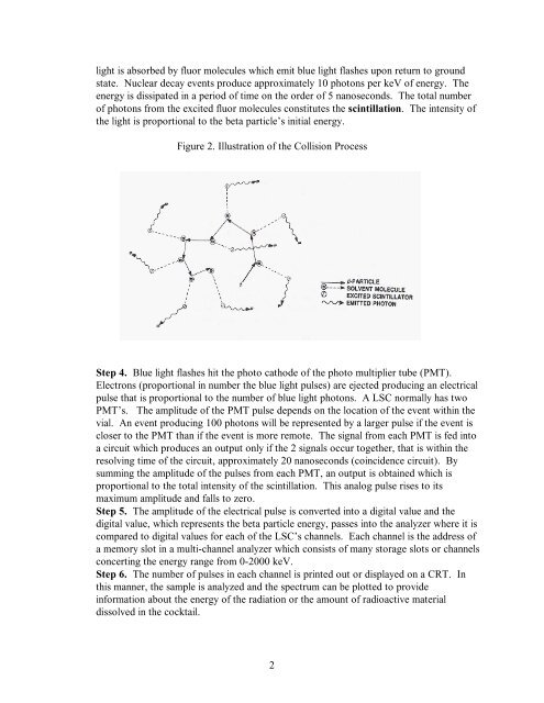
light is absorbed by fluor molecules which emit blue light flashes upon return to ground<br />
state. Nuclear decay events produce approximately 10 photons per keV of energy. The<br />
energy is dissipated in a period of time on the order of 5 nanoseconds. The total number<br />
of photons from the excited fluor molecules constitutes the scintillation. The intensity of<br />
the light is proportional to the beta particle’s initial energy.<br />
Figure 2. Illustration of the Collision Process<br />
Step 4. Blue light flashes hit the photo cathode of the photo multiplier tube (PMT).<br />
Electrons (proportional in number the blue light pulses) are ejected producing an electrical<br />
pulse that is proportional to the number of blue light photons. A LSC normally has two<br />
PMT’s. The amplitude of the PMT pulse depends on the location of the event within the<br />
vial. An event producing 100 photons will be represented by a larger pulse if the event is<br />
closer to the PMT than if the event is more remote. The signal from each PMT is fed into<br />
a circuit which produces an output only if the 2 signals occur together, that is within the<br />
resolving time of the circuit, approximately 20 nanoseconds (coincidence circuit). By<br />
summing the amplitude of the pulses from each PMT, an output is obtained which is<br />
proportional to the total intensity of the scintillation. This analog pulse rises to its<br />
maximum amplitude and falls to zero.<br />
Step 5. The amplitude of the electrical pulse is converted into a digital value and the<br />
digital value, which represents the beta particle energy, passes into the analyzer where it is<br />
compared to digital values for each of the LSC’s channels. Each channel is the address of<br />
a memory slot in a multi-channel analyzer which consists of many storage slots or channels<br />
concerting the energy range from 0-2000 keV.<br />
Step 6. The number of pulses in each channel is printed out or displayed on a CRT. In<br />
this manner, the sample is analyzed and the spectrum can be plotted to provide<br />
information about the energy of the radiation or the amount of radioactive material<br />
dissolved in the cocktail.<br />
2