SE LP10 - Access Control Solutions from ASSA ABLOY
SE LP10 - Access Control Solutions from ASSA ABLOY
SE LP10 - Access Control Solutions from ASSA ABLOY

Create successful ePaper yourself
Turn your PDF publications into a flip-book with our unique Google optimized e-Paper software.
<strong>SE</strong> <strong>LP10</strong> Mortise Lock<br />
9<br />
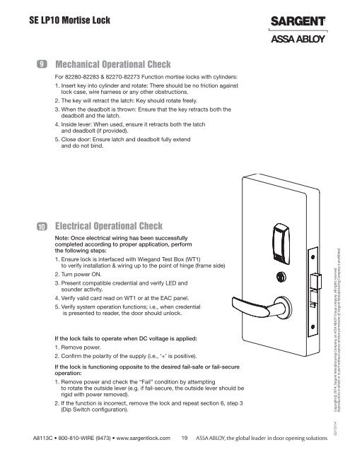
Mechanical Operational Check<br />
For 82280-82283 & 82270-82273 Function mortise locks with cylinders:<br />
1. Insert key into cylinder and rotate: There should be no friction against<br />
lock case, wire harness or any other obstructions.<br />
2. The key will retract the latch: Key should rotate freely.<br />
3. When the deadbolt is thrown: Ensure that the key retracts both the<br />
deadbolt and the latch.<br />
4. Inside lever: When used, ensure it retracts both the latch<br />
and deadbolt (if provided).<br />
5. Close door: Ensure latch and deadbolt fully extend<br />
and do not bind.<br />
10<br />
Electrical Operational Check<br />
Note: Once electrical wiring has been successfully<br />
completed according to proper application, perform<br />
the following steps:<br />
1. Ensure lock is interfaced with Wiegand Test Box (WT1)<br />
to verify installation & wiring up to the point of hinge (frame side)<br />
2. Turn power ON.<br />
3. Present compatible credential and verify LED and<br />
sounder activity.<br />
4. Verify valid card read on WT1 or at the EAC panel.<br />
5. Verify system operation functions; i.e., when credential<br />
is presented to reader, the door should unlock.<br />
If the lock fails to operate when DC voltage is applied:<br />
1. Remove power.<br />
2. Confirm the polarity of the supply (i.e., ‘+’ is positive).<br />
If the lock is functioning opposite to the desired fail-safe or fail-secure<br />
operation:<br />
1. Remove power and check the “Fail” condition by attempting<br />
to rotate the outside lever (e.g. if fail-secure, the outside lever should be<br />
rigid with power removed).<br />
2. If the function is incorrect, remove the lock and repeat section 6, step 3<br />
(Dip Switch configuration).<br />
A8113C • 800-810-WIRE (9473) • www.sargentlock.com 19<br />
02/15/14 Copyright © 2014, Sargent Manufacturing Company, an <strong>ASSA</strong> <strong>ABLOY</strong> Group company. All rights reserved.<br />
Reproductions in whole or in part without express written permission of Sargent Manufacturing Company is prohibited.