Mini Max MM20 Band S.. - Valley Woodworkers
Mini Max MM20 Band S.. - Valley Woodworkers
Mini Max MM20 Band S.. - Valley Woodworkers

You also want an ePaper? Increase the reach of your titles
YUMPU automatically turns print PDFs into web optimized ePapers that Google loves.
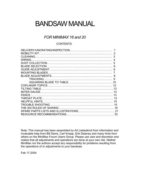
BANDSAW MANUAL<br />
FOR MINIMAX 16 and 20<br />
CONTENTS<br />
DELIVERY/UNCRATING/INSPECTION………………………………………. 1<br />
MOBILITY KIT……………………………………………………………………. 2<br />
CLEANING……………………………………………………………………….. 3<br />
WIRING…………………………………………………………………………… 4<br />
DUST COLLECTION……………………………………………………………. 5<br />
BLADE SELECTION…………………………………………………………….. 6<br />
GUIDE ADJUSTMENT………………………………………………………….. 6<br />
MOUNTING BLADES…………………………………………………………… 7<br />
BLADE ADJUSTMENTS………………………………………………………... 8<br />
TRACKING……………………………………………………………….. 9<br />
SQUARING BLADE TO TABLE…………………………………………10<br />
COPLANAR TOPICS……………………………………………………………. 12<br />
TILTING TABLE……………………………………………………………………13<br />
MITER GAUGE…………………………………………………………………… 13<br />
FENCE…………………………………………………………………………….. 13<br />
THROAT PLATE………………………………………………………………….. 13<br />
HELPFUL HINTS…………………………………………………………………. 15<br />
TROUBLE SHOOTING…………………………………………………………... 15<br />
THE SIX RULES OF SAWING…………………………………………………... 16<br />
SPARE PARTS LISTS AND ILLUSTRATIONS………………………………… 21<br />
RESOURCE RECOMMENDATIONS…………………………………………… 33<br />
Note: This manual has been assembled by Art Liebeskind from information and<br />
invaluable help from Bill Sams, Carl Knapp, Erik Delaney and many hints from<br />
others on the <strong>Mini</strong><strong>Max</strong> Forum Users Group. Please use care and discretion and<br />
realize that all adjustments and operations are done at your own risk. Neither<br />
<strong>Mini</strong><strong>Max</strong> nor the authors accept any responsibility for problems resulting from<br />
the operations of or adjustments to your bandsaw.<br />
Feb 17,2004
<strong>Mini</strong><strong>Max</strong> <strong>Band</strong>saw<br />
User’s Manual For<br />
MM 16 & 20<br />
DELIVERY UNCRATING AND INSPECTION<br />
Delivery<br />
You have made the right decision and now you are anxiously awaiting<br />
delivery. Right now, call the trucking company and make arrangements<br />
to get the machine into your shop. There are a number of options<br />
including :<br />
• self pick up at the terminal,<br />
• lift gate truck delivery to<br />
your location<br />
• or even the use of a<br />
machine rigger who will<br />
pick up the saw and place it<br />
at the point of use in your<br />
shop<br />
If you want to move the pallet you may of<br />
course use a simple pallet jack, a forklift<br />
(if you are fortunate enough to have the<br />
use of one), or the unit may be lifted and<br />
moved by a hoist connected to the lift<br />
holes at the top of the saw. See Figure 1<br />
Hoist Holes, at right. Lifting is done by<br />
passing a rope through the holes in the<br />
top of the machine. On completing the<br />
operation, close the above mentioned<br />
holes with the plastic caps provided.<br />
At any rate in addition to moving and lifting<br />
tackle, have refreshments and one or more<br />
strong friends on hand since the saw weighs about 450 pounds. The Saw will be<br />
crated and shrink wrapped on a pallet as seen below in Figure 2 Crated Saw.<br />
Obviously this packaging must be removed in order to check the condition of the<br />
sawand continue with the commissioning process.<br />
1
Inspection and Uncrating<br />
Your <strong>Mini</strong> <strong>Max</strong> <strong>Band</strong>saw is heavily built but it is not immune to shipping<br />
damage. Please inspect your saw thoroughly<br />
before signing for the machine! Inspect the<br />
crate, pallet and the actual machine for any<br />
dings, dents or crate damage. If you see<br />
anything, do not sign the delivery receipt and call<br />
<strong>Mini</strong> <strong>Max</strong> immediately at this toll free number<br />
(866-975-9663)!<br />
If you have access to a camera, photo<br />
evidence is extremely helpful. Pull out the<br />
packing list and check to see that all of your<br />
accessories are there. Confirm that if there are<br />
accessories missing,this fact shows as a back<br />
order notation on the packing list.<br />
Now that you have your bandsaw<br />
delivered safely to your shop, you can begin the<br />
uncrating process. You can use a hammer with<br />
a pry bar or even a reciprocating saw to remove<br />
the crate from the saw. Cut the plastic off the<br />
machine and remove it. Inside the plastic you<br />
will find a black plastic tool kit. The tool kit<br />
includes a push stick, allen wrenches, open end<br />
wrenches, a factory manual and 4 leveling bolts. See Figure 3, Tool Kit . Use the<br />
appropriate metric wrench in your tool kit to remove the two lag bolts that<br />
secured your saw to the frame. Once you have removed the bolts slide the<br />
bandsaw off the pallet. or lift the saw, with the two hoist holes on the top of the<br />
saw.Please be careful and observe all normal precautions and safety procedures<br />
while working on, moving, and operating this machine.<br />
MOBILITY KIT<br />
If you purchased the mobility kit you will only<br />
use two of the leveling bolts found in the toolkit.<br />
Mount the wheels to the left side of the base of<br />
the saw using the two bolts supplied. See<br />
Figure 4 Below, Mobility Wheels Mounted. An<br />
easy way to do this is tilt the saw up and slide a<br />
piece of wood under the frame. This will give<br />
you the clearance you will need to mount the wheel<br />
bracket. The Johnson bar then gets placed<br />
2
under the footbrake and you are ready to roll the machine around. See Figure 5<br />
Below, Johnson Bar Placement. Note: Always be careful where you place your<br />
Johnson. The bar can be easily and handily stored by placing the hook in one of<br />
the empty lift holes at the top of the saw.<br />
If you will not use the Mobility system,<br />
Insert the leveling bolts into the<br />
threaded holes as shown below. See<br />
Figure 6, Leveling bolts, Below.<br />
Turn the bolts “in” to raise that end of<br />
the machine. Most users have found<br />
that the machine is stable without<br />
being bolted to the floor. Although the<br />
regular manual suggests this, you may<br />
use your own judgement. Obviously if<br />
you use the mobility system, it will not<br />
be bolted down. Another option is to<br />
use wooden wedges. If the machine is moved<br />
even a few inches, the floor could<br />
change the level.. With a wooden wedge the short leg can be found and the<br />
wedge pushed under a little further to reestablish the level. If the machine is<br />
going to stay put, it is helpful to put rubber pads under the bearing legs. Glue a<br />
piece of wood to the pads as needed for level operation. This is better than<br />
having the machine resting only on leveling bolts<br />
CLEANING AND ELECTRICAL NEEDS<br />
Cleaning<br />
You are now ready to start the cleaning process. Be sure to clean all the<br />
cosmoline grease off the machine. You can use WD40, Kerosene or one of the<br />
citrus based solvents. One important side note is to remove the clear plastic<br />
blade guard and clean that only with soap and water. Oil based solvents like<br />
3
WD40 or mineral spirits will cause the guard to fog permanently. Pay special<br />
attention to cleaning the 3 micro switches on the saw), one connected to the foot<br />
pedal (behind lower wheel), one each behind upper and lower doors<br />
Take your time when cleaning the machine. This will give you the opportunity to<br />
to familiarize yourself with this new addition to the shop.<br />
Wiring<br />
Now that you have spent the last 60-90 minutes cleaning the machine you<br />
are ready to get the machine set up electrically<br />
NOTE: DISCONNECT ALL POWER BEFORE ATTEMPTING FOLLOWING<br />
PROCEDURE!!!!! MINIMAX STRONGLY SUGGESTS THAT YOUR WIRING<br />
AND CIRCUIT INSTALLATION BE DONE BY A LICENSED ELECTRICIAN<br />
ACCORDING TO YOUR LOCAL CODE!<br />
You will need to wire your saw to a 220/240V outlet. Depending on the<br />
saw you purchased you will need a 20 amp or 30 amp breaker separate circuit.<br />
Many MM16’s run very nicely with a 20 Amp circuit and #10 or 12 wire. Similarly<br />
many use a 30 amp circuit with #10 wire for the <strong>MM20</strong>. If there is any question in<br />
your mind, contact an electrician! (See Figure 7 Electrical Nameplate )<br />
If you purchased a single phase machine (all MM16’s and single phase<br />
<strong>MM20</strong>’s) the machine will have 3 wires. The yellow/green wire is the ground and<br />
the other two are your hot wires. It does not<br />
have or use a neutral wire.<br />
If your machine is 3 phase and the<br />
machine is running backwards, disconnect the<br />
power and switch two of the hot legs.<br />
The MM16 has a short cord on the machine.<br />
You can:<br />
• connect a twist lock plug to it and then run<br />
an extension cord to it,<br />
• wire the existing cord to a junction box that<br />
you add<br />
• ,or, you can replace the existing cord and<br />
hard wire the machine.<br />
The <strong>MM20</strong> has a small junction box already on<br />
the machine. (See Figure 8, <strong>MM20</strong> Box)<br />
ONCE AGAIN: Make sure the machine is<br />
disconnected from the power source when wiring<br />
the machine or the circuit breaker is turned<br />
off(put a piece of tape on the breaker switch to<br />
prevent accidentally turning the electricity on) if<br />
you are hard wiring the machine !!!!!<br />
To turn the machine on, First make sure both<br />
upper and lower doors are closed. Micro switches<br />
control the upper and lower doors and the foot brake.<br />
The <strong>Band</strong> Saw has a larger red off button and black on<br />
button. (See Figure 9 On Off Switch) The off button<br />
4
needs to be reset to restart the saw. The Off button may need to be pulled out or<br />
twisted GENTLY to reset it, depending on the type of switch on your machine. It<br />
is perfectly allright to test start the machine without a blade. If it does not start,<br />
make sure the doors are closed and also be sure that there is no Cosmoline<br />
gumming the safety microswitches.<br />
DUST COLLECTION PORT SIZE AND AIR REQUIREMENTS<br />
Dust Collection<br />
Both the MM16 and <strong>MM20</strong> have a 100mm(very close to 4”) extraction<br />
port located on the mid right side of the saw See Figure 10 Dust Outlet. You may<br />
connect a 4" flex hose directly or use a quick disconnect adaptor flange - 4" flex<br />
hose to 100mm (available from Onieda Air Systems, see sources). Depending on<br />
the particular hose or parts you get, it may be necessary to use a rubber<br />
plumbing connector (4”) with two hose clamps to adapt your hose or the quick<br />
disconnect to the outlet.<br />
A replaceable plywood deflector below the lower guides helps direct<br />
the dust to the port.See<br />
Figure 11 Dust Deflector..<br />
CFM Requirements)<br />
For a 4” Flex tube, a conservative estimate is about 800 cfm on your<br />
collection system to capture dust effectively. The actual figure can be estimated<br />
by a Cyclone or dust collection supplier such as Oneida Air( See resources).It of<br />
course depends on the distance from the collector and the pipe sizes and<br />
geometry.<br />
BLADE SELECTION/GUIDE ADJUSTMENT/MOUNTING<br />
BLADES<br />
Blade Selection (BE CAREFUL, BLADES ARE SHARP!)<br />
5
WIDTHS: Common blade widths are 1 1/4", 1", 3/4", 1/2", 3/8" ,1/4" , 1/8", 1/16"<br />
You will find that 1", 1/2", 1/4" blades cover a wide range of woodworking tasks.<br />
TEETH: The number of teeth per inch of blade (TPI) will range from 3 TPI to as<br />
high as 14 TPI. Rough work and very thick wood uses fewer TPI while narrower<br />
widths and fine work use higher TPI.<br />
TOOTH TYPE: Hook/Skip type are good for re-sawing, ripping or joinery<br />
BLADE TYPES:Blades can be had in carbon steel, Bi-metal or carbide tipped<br />
blades. General woodworking needs can be met with a variety of types. Both<br />
Carbon steel and Bimetal can be very effective. Carbide blades are a powerful<br />
addition to resaw capability but must be suited to the saw.For example, the 1”<br />
wide carbide blade offered by <strong>Mini</strong> <strong>Max</strong> is not recommended for the MM16<br />
because the smaller wheel radius flexes and work hardens the blade leading to<br />
premature breakage before dulling. A 1” Carbide is however very well suited and<br />
effective on the <strong>MM20</strong> and larger saws.<br />
Note: <strong>Mini</strong> <strong>Max</strong> sells the Olson line of bandsaw blades. other options are offered<br />
in our sources section.<br />
GUIDE INSPECTION AND ADJUSTMENT<br />
The guides are European ball-bearing type For very narrow width blades,<br />
<strong>Mini</strong><strong>Max</strong> is developing a “cool block” guide system for using 1/8" and smaller<br />
blades<br />
LOWER GUIDES<br />
On the MM16 or <strong>MM20</strong>, remove the lower guides. (See Figure12 Lower Guides)<br />
This is a good chance to check to see if the guides are cleaned of the Cosmoline!<br />
Loosen the allen screws (in the back) that hold the guides to the aluminum<br />
bracket. Align the guides and tighten the allen screws.<br />
Back the guides off and then move them back together<br />
to double check the adjustment before re-installing the<br />
guides. While the guides<br />
are out, sight them from<br />
the top to make sure the<br />
two guides are toed in<br />
slightly towards the front.<br />
(this is what makes them<br />
spin and captures the<br />
blade just behind the<br />
gullets) If they are not,or the<br />
guide wheels spin in opposite<br />
directions when the saw is run with a blade installed, call the Austin Office to<br />
report it and get instructions for a fix.<br />
UPPER GUIDES<br />
starting with the top guides ( See Figure 13 Upper Guides)<br />
1).Screw the two side guides in and make sure they are meeting up<br />
with each other like stacking coins. If they do not match up, loosen the<br />
two allen screws from the back and then adjust (twist) the guides so<br />
6
that they meet each other perfectly.<br />
2) Tighten the allen screws.<br />
3) Open the guides up a little and then bring them back together to<br />
make sure that they meet up correctly. This is to make sure that the bit<br />
of play in the guides does not give a false indication as to how they<br />
meet.<br />
4) Next, screw the guides together with the adjuster knob so that they<br />
just barely touch. Sight them from the top and see that they are toed or<br />
angled forward just a little and that the inner and outer look the same.<br />
If they are close, all is ready for installation of the blade<br />
MOUNTING BLADES<br />
NOTE:BE SURE POWER IS DISCONNECTED FROM SAW<br />
Back the guides off (open them) and install the blade as follows:<br />
1- Remove clear plastic guard<br />
2- Open cabinet doors<br />
3- Raise telescoping blade guard (See Figure 14 Guard Assembly<br />
4- Adjust upper & lower guide assemblies<br />
out of the way of the insertion of blade<br />
5- Insert blade on tires, adjust so teeth are<br />
just barely protruding beyond outside edge<br />
of tires (teeth should point downward<br />
toward table, if not turn blade inside out)<br />
6- Adjust tension<br />
7- Adjust tracking by spinning wheel<br />
manually to check tracking and blade location<br />
8- Check that the plane of the top and bottom<br />
wheels are in the same plane(Coplanar, see<br />
Coplanar section) Note that many experts insist<br />
that this is not an issue with flat tires such as<br />
those on the <strong>Mini</strong><strong>Max</strong> bandsaws.<br />
9- Adjust upper and lower thrust bearing 1/64 (<br />
.016 ) inch gap behind blade. Check to see if<br />
the back of the blade lines up with the thrust<br />
bearing in the correct place. The back of the<br />
blade should make contact close to the center<br />
of the outer machined area of the trust bearing. If the blade is too far out on the<br />
edge, the blade will tend to slide off the edge. If the blade is too far towards the<br />
center, the thrust bearing may not spin correctly and may be damaged. A one<br />
time adjustment for positioning the thrust bearing may be made on the top guides<br />
by loosening the bracket holding the entire guide assembly to the bottom of the<br />
guide post. It slides the guide diagonally to move the bearing side to side.(See<br />
7
Figure 15 Horizontal Adjustment) The blade should never hit the thrust<br />
bearing until the wood pushes the blade back during cutting.<br />
10) On the lower guides, you need to make a similar check of the alignment of<br />
the back of the blade to the thrust bearing as you raise or lower the guides in<br />
reference to the table. Note there are two pivot points on the lower guides to<br />
adjust them parallel with the blade.<br />
At this point the top and bottom guides are set up and ready to be set for the<br />
particular blade.<br />
11) Loosen the bolt that fastens thede the round rod forward. Slide the rod and<br />
guides forward, so that the front edge of the side guide is just behind the gullet.<br />
Look from the front to make sure the guides are parallel with the blade as the bolt<br />
is tightened.<br />
12) Adjust upper and lower guide bearing leaving .004 inch gap between blade<br />
and bearing (Thickness of a dollar bill folded once) Adjust the side guides in<br />
while you are spinning them with a finger. When the guide can be felt just<br />
touching the blade, back it off a hair. Now tighten the lock. As the lock ring<br />
tightens, turn the guide adjustment with it to cinch it down securely. Now spin the<br />
guide. You should barely feel it touch the blade<br />
11) Close doors and reinstall plastic blade guard<br />
12) Rotate blade by hand to check tracking<br />
13- Plug in saw, turn power on to check operation<br />
ADJUSTMENTS (TENSIONING, BLADE TRACKING<br />
SQUARING BLADE TO TABLE)<br />
ADJUSTMENTS<br />
Tuning and tweaking a bandsaw is the key to accurate, precise and<br />
simple cutting. Your enjoyment will be in direct proportion to the energy you<br />
expend on fine adjustment and tune-up.<br />
<strong>Mini</strong><strong>Max</strong> bandsaws have “flat” tires versus “crowned” tires.The flat tire offers<br />
better support for the blade while cutting and increases accuracy.<br />
TENSIONING A BANDSAW BLADE<br />
The tension gauge supplied on the machine does not show true tension<br />
but rather serves as a point of reference. See<br />
Figure 16 Tension Gauge. It serves that<br />
reference function best after you establish the<br />
correct tension for each blade. See Figure 17<br />
Tension Aduster<br />
Correct really means the tension that works<br />
best for the particular blade in use.) Set<br />
tension by gently pushing blade sideways<br />
with finger. The blade should deflect<br />
approximately 3/8 inch sideways with the<br />
telescoping blade guard at full<br />
8
height or about 1/4" deflection<br />
when distance between upper<br />
and lower guides is set at 6" or<br />
less. Because each person’s<br />
definition of moderate pressure<br />
varies you may wish to borrow or<br />
purchase a tension indicator.<br />
If using some of the so<br />
called “lower tension” blades, it is<br />
strongly suggested that the<br />
manufacturer’s instructions be<br />
followed. A few suppliers are<br />
listed in the sources section.<br />
Carbide, Bi Metal, Stellite and Carbon steel blades require different<br />
amounts of tension ranging from 15,000 to 30,000 psi.<br />
Once you find the proper tension for the blade(s) you use you can create your<br />
own indicator marks lines for repeatability. A good recommendation is to use<br />
different colored markers and color code the different blade widths.<br />
TRACKING<br />
You can not track a blade until the proper tension has been set! Pay careful<br />
attention to the preceding section on proper tensioning of the blade. The width<br />
of the blade dictates where it should run on the tire.<br />
A rule of thumb suggests that anything over a ½” blade should have the teeth<br />
slightly over hang the tire. This is to prevent premature wearing of the tires.<br />
Smaller bl run as close to the center of the wheel as possible. This is to<br />
9
prevent the blade from “walking” off the wheel.<br />
The knob on the back of the upper cabinet is the tilt adjustment on the<br />
upper wheel. See Figure 18 Tilt Adjuster. This knob allows you to change the<br />
position of the blade on the tire. Loosen the locking gib and then rotate the<br />
knob. Always rotate the wheels backwards when adjusting the saw. This will<br />
decrease the possibility of you catching a tooth on something if the blade was<br />
too far forward. Once you set the blade for the upper wheel lock the gib handle<br />
back in place.<br />
The lower wheel can be adjusted at the rear of lower cabinet. There<br />
are four bolts. DO NOT TOUCH THE BOLTS AT 3 & 9 O’CLOCK!!! (Right<br />
and Left)<br />
See Figure 19 Lower Wheel Adjustment. To tilt the wheel Back (Top further<br />
from the door), loosen the center hub bolt, loosen the lower bolt and tighten the<br />
upper bolt. To tilt the wheel Forward(Top closer to the door), loosen the top and<br />
tighten the bottom. Again rotate the wheels in reverse to check where the blade<br />
end up. Once the lower blade is tracking to your satisfaction, lock the hub bolt<br />
again.<br />
SQUARING BLADE TO TABLE<br />
SIDE TO SIDE SQUARENESS<br />
After all tracking and tensioning of the blade is accomplished, check the blade for<br />
table squareness. Use a simple machinists square. If the table is grossly out of<br />
square with the blade, check to see if the table tilt mechanism has been moved.<br />
If so, loosen the trunnion clamp bolt and square the table. To square the table to<br />
the side of the blade, first loosen the large single bolt (within the table tilt scale)<br />
which secures the table to the frame. (See Figure 20 TABLE ADJUSMENT).<br />
Then adjust the angle by turning the positive stop bolt (small bolt and nut on<br />
underside of table (See Figure 21 POSITIVE STOP) in either direction then<br />
pushing the table up or down, until the table is square with the blade.And the<br />
table is against the positive stop. Tighten large trunnion bolt.<br />
10
FRONT TO BACK SQUARENESS OF TABLE TO BLADE<br />
Use the four adjusting bolts in the trunnion on the under side of the table for<br />
adjusting the back of the blade to the table (See Figure 20 TABLE<br />
ADJUSTMENT again) . These are bolts with lock nuts and they can push or pull<br />
on the table. Experiment with loosening and tightening these adjusters till the<br />
table is square to the back of the blade.<br />
VERTICAL GUIDE POST ADJUSTMENTS<br />
Adjustment of the vertical guide post requires that the lock knob on the side of<br />
the saw be loosened,and the adjusting knob turned to raise or lower the guide<br />
assembly..(See Figure 22 GUIDE POST ADJUSTMENT). When re-positioning<br />
the height of the upper guide assembly to be close to the height of the material to<br />
be cut, the guide bearing adjustments made earlier should stay in position and inline<br />
with the blade. If not, loosen the two<br />
center bolts See Figure 23 UPPER<br />
GUIDE POST ALIGNMENT) behind the<br />
locking knob and move lightly by hand<br />
until the bearings remain in line even with<br />
vertical movement of the guide post.<br />
The lower guide assembly can also be<br />
adjusted vertically to give firmer support to<br />
the blade while cutting. In other words<br />
moved closer to the underside of the<br />
table. Adjust by loosening the 17mm bolt<br />
(See Figure 24 Lower Guide Adjust Bolt)<br />
that clamps the lower assembly and slide the assembly up or downup or down.<br />
Tighten the securing bolt.<br />
11
ADJUSTMENTS TO THE PLANE OF THE WHEELS<br />
Coplanar in <strong>Band</strong>saw terms means that the upper and lower wheel<br />
faces are in exactly the same plane . This state keeps the blade well supported<br />
for accurate sawing and blade tracking. There are differences of opinion as to<br />
whether a flat wheeled saw such as the <strong>Mini</strong><strong>Max</strong> MM16 and <strong>MM20</strong> really needs<br />
to be coplanar. Nevertheless, the following routine will indicate whether your<br />
wheels are in the same plane and will present instructions for achieving this<br />
advanced state.<br />
Wheels are adjusted to the same plane at the factory using the<br />
appropriate settings for a 1 ¼” blade. This may not necessarily mean that the<br />
wheels will be coplanar for smaller width blades. The reality is that when smaller<br />
blades (ie 1/2") are used, the blade may not track exactly the same on both the<br />
upper and lower wheels. This is normal and perfectly okay as long as the back of<br />
the blade remains square to the table. If it is not square to the table, the following<br />
adjustments will help whether you are aiming for a coplanar condition or not.<br />
STEPS TO ADJUST THE PLANES OF THE WHEEL (COPLANAR)<br />
1) Prepare a 3/4" plywood template approximately 10" wide, by 67" long with one<br />
edge perfectly straight<br />
2) Cut an arc out of the template to bypass table, (or remove table). Cut notches<br />
as needed to bypass the wheel hubs and the saw frame.<br />
3) With your widest blade on and fully tensioned hold the template against the<br />
face of the upper and lower wheels. If the wheels are coplanar, the straight edge<br />
of the plywood template will be in contact with the top and bottom of each wheel.<br />
4) If there is a gap on either the top or bottom on the lower wheel, then the plane<br />
of the wheel needs adjustment.<br />
5) On lower wheel hub on outside of frame, loosen center bolt, loosen lock nuts<br />
on the appropriate bolts to adjust (usually top and bottom at “6 and 12 o’clock)<br />
( See Section on wheel adjustment above and See Figure25 Lower Wheel<br />
Adjustment), adjust wheel into coplanar<br />
by<br />
loosening one and tightening the other<br />
in order to tilt the wheel in the desired<br />
direction.<br />
6) Reheck with template; tighten<br />
locknuts and center hub bolt;<br />
7) Stabilize blade by spinning the<br />
wheels by hand. This will indicate how<br />
the blade will track and thus position<br />
the blade to check for not only the<br />
same planes for both wheels but the<br />
squareness of the blade back to the<br />
table.<br />
12
TILTING THE TABLE, ADJUSTING THE MITER GAUGE,<br />
FENCE, AND THROAT PLATE<br />
TABLE TILTING<br />
The bandsaw table will tilt up to 45 degrees. To tilt the table loosen the large bolt<br />
enough for the table to slide in both trunions in the table tilt scale and adjust tilt<br />
by hand (SEE FIGURE 26 TRUNNION BOLT). Tighten the bolt. Note that if the<br />
lower guide assembly has been positioned close to the bottom of the table it will<br />
be necessary to move this guide assembly down in order to tilt the table more<br />
than 10 degrees. On some machines, if the bolt is only partially loosened, the<br />
left trunnion tends to bind a bit.<br />
You can tilt about 8-10 degrees in<br />
the opposite direction by removing<br />
the zero degree positive stop at<br />
the rear underside of the table.(SEE FIGURE 27,<br />
POSITIVE STOP BOLT) . This<br />
may be desirable for such<br />
operations as cutting <strong>Band</strong>sawn<br />
dovetails where the ability to tilt in<br />
both directions is useful.<br />
On some saws, the tilt mechanism trunnions are very tight. This can be eased<br />
by removing the table and using some very fine valve grinding(abrasive)<br />
compound to loosen the sliding action of the trunnion. Valve grinding compound<br />
13
looks like a gray sharpening stone that was turned into paste. It can be found at<br />
an auto parts store where both coarse and fine is available. Both grits are useful<br />
to polish trunnions, miter slots, and the kinds of roughness or binding often found<br />
on machine tools.<br />
MITER GAUGE AND SLOT<br />
If the miter gauge binds in the slot, slide it along the slot to find out where it<br />
binds. Use a fine file dragged along the edge of the slot. Then polish the slot and<br />
the miter gauge bar with some fine emery cloth. A piece of oak to back up the<br />
emery cloth will keep the repair flat and square. Frankly, a miter gauge is of very<br />
little use on a bandsaw so don’t waste too much time adjusting it.<br />
ADJUSTING THE FENCE<br />
Fence and Blade drift<br />
Blade drift means the blade isn’t cutting<br />
parallel to the fence. Every blade will<br />
cut in a slightly different manner and<br />
you may have to adjust the fence angle<br />
to compensate for this drift. To check<br />
blade drift, mark a straight line on a<br />
board 24" long, rip the board freehand<br />
while carefully following the line About<br />
halfway, through the cut, stop the saw<br />
and leave the board in place. Mark the<br />
side of the board on the saw table with<br />
a soft pencil. This line indicates the<br />
appropriate angle for the fence. Move and<br />
adjust the fence parallel to this line (and<br />
therefore parallel to the direction that the particular blade wants to cut).The fence<br />
angle may be adjusted by loosening the top bolt in the fence assembly. Pivot the<br />
fence about the roll pin and tighten the bolt. (SEE FIGURE 28 FENCE<br />
ADJUSTMENT BOLT).<br />
THROAT PLATE ADJUSTMENT<br />
The height of the throat plate is adjusted by 4 screws. A fine screwdriver may be<br />
used to adjust the plate absolutely flush to the table.(SEE FIGURE 29 THROAT<br />
PLATE ADJUSTMENT<br />
14
HELPFUL HINTS<br />
BLADE SELECTION: What blade for what purpose <br />
RE-SAWING/RIPPING: 1" Blade with 3/4 pitch (tpi) hook/skip tooth blade<br />
LIGHT RE-SAWING/RIPPING: ½”Blade with 3/4 pitch hook/skip tooth blade<br />
CURVES AND JOINERY: ½” Blade with 8/10 pitch(tpi) for joinery cuts and curves<br />
larger than 2 -1/4"radius<br />
TIGHTER CURVES: 1/4" Blade with 8/10 pitch for joinery and curves larger than<br />
3/8" radius<br />
GENERAL SMART THINGS TO DO<br />
Clean table and fence frequently and wax with paste wax to eliminate friction.<br />
Round back of blade with file or honing stone to eliminate scouring of thrust<br />
bearing and help prevent binding while cutting curves.<br />
Coat the blade with paraffin/blade lube to ease cutting and reduce pitch buildup.<br />
(Spray “PAM” works well.)<br />
Check bearings for sawdust buildup to prevent damage to bearings.<br />
Keep holes in “table insert” clear for effective dust collection.<br />
Always remove tension from blade at the end of day (establish a “signal” such<br />
as a ribbon to hang from the door as a reminder to retension before starting<br />
the saw!)<br />
TROUBLE SHOOTING CHART<br />
THE PROBLEM PROBABLE CAUSE ACTION<br />
Motor won’t start No current in circuit 1. Plug saw in<br />
2. Check circuit breaker in the dedicated<br />
circuit.<br />
3. Check if stop button is released.<br />
Clean cosmoline from micro-switches on<br />
doors and brake(stuck open)<br />
4. Adjust door switches by loosening switch<br />
holder nuts and move switch towards door.<br />
Listen for the click when switch is in<br />
Motor overheats Wrong voltage 1. Check circuit voltage<br />
2. Check wiring diagram be sure it is<br />
15
Blade doesn’t cut<br />
straight<br />
Blade wobbles<br />
Dull or badly sharpened or<br />
set blade<br />
Wheels not coplanar, Low<br />
blade tensioning, Guides or<br />
bearings not adjusted<br />
properly<br />
followed in hookup.to voltage on nameplate<br />
1. Change blade<br />
2. Sharpen and set if you are an expert<br />
1. Adjust as in section ”ADJUSTMENTS<br />
TO THE PLANE OF THE WHEELS”.<br />
2. Increase blade tension as in “BLADE<br />
MOUNTING/TENSIONING” Section.<br />
3. Adjust guide settings as in “GUIDE<br />
ADJUSTMENT SECTION”.<br />
4. Check for bad weld on blade.<br />
Blade “Ticking” Crooked weld on blade 1. Smooth weld with file<br />
2. carefully hone with stone while blade is<br />
running<br />
SIX STEPS FOR BANDSAWS With permission from<br />
“SUFFOLK SAW/TIMBERWOLF” © 2003 Suffolk Machinery<br />
Corporation. All Rights Reserved.<br />
THE SIX RULES OF SAWING<br />
FOR TURN SCREW AND SPRING TENSIONING MACHINES<br />
Remove guides--you CANNOT run this test if the band saw<br />
blade is restricted in any lateral movement.<br />
Make sure tire surfaces are in good condition--they cannot be<br />
hard, flattened out, cracked or brittle. On mills with loose<br />
fitting V-belts, replace them with the next size down so they<br />
are tight fitting. This will eliminate over 80% of the vibration<br />
in your mill and the blade.<br />
Mount the blade on the machine and apply the tension to the<br />
band that the manufacturer recommends for other steels.<br />
Close all covers for safety purposes.<br />
Start the machine, engage the clutch into the high speed cutting<br />
mode. NOTE: You will not be cutting any wood.<br />
Stand at the head of the machine, with your hand on the turn<br />
screw tensioner and your eyes on the band saw blade. Very<br />
slowly start detensioning by half turns at a time, keeping<br />
your eyes on the band saw blade. The object is to bring the<br />
tension of the blade down to a point that the blade starts to<br />
flutter. TAKE YOUR TIME.<br />
When you see the band start to flutter, you have hit ground<br />
"ZERO". Now start ADDING quarter turns of tension,<br />
SLOWLY, until the band stops fluttering and is running<br />
16
stable again. At this point ADD one-eight to one-quarter turn<br />
of tension.<br />
You have now tensioned our blade correctly. Shut off the<br />
machine and put your guides back in place. You are now<br />
ready to start sawing.<br />
ALWAYS DETENSION YOUR BAND SAW BLADES. Since you<br />
do not know exactly where the proper tension is, it will be<br />
easier to remember if you take off 8, 9, or 10 full turns of<br />
tension until the band is completely relaxed. The next time<br />
you use our bands, add the same amount of turns of tension<br />
that were taken off. At this point, you will only have to run the<br />
flutter test one time.<br />
WARNING: IF YOU DO NOT RUN THE FLUTTER TEST ON OUR<br />
SPECIAL SILICON STEEL BLADES, YOU WILL NOT ACHIEVE<br />
THE ENDURANCE AND LONGEVITY THAT OUR HIGH DUCTILE<br />
BANDS ARE CAPABLE OF.<br />
CHOOSING THE PROPER BAND SAW BLADE LUBRICATION<br />
NEVER USE WATER as a lubricant on band saw blades. Water is<br />
NOT a lubricant and is the WRONG thing to use for many reasons.<br />
For the woodworker using 1" and 1 1/4" bands, not only is water<br />
unacceptable as a lubricant, but it also rusts the bands<br />
causing deep pitting, and inappropriate chip swelling. This<br />
prematurely destroys the body of the band and its gullets. It<br />
also dry rots your tires or V-belts.<br />
For proper lubrication mix HIGH ADHESION CHAIN SAW<br />
BAR OIL, with 50% kerosene or diesel fuel. Apply the<br />
solution with a spray bottle to BOTH sides of the band about<br />
once every four minutes, while the machine is running.<br />
When this lubrication is applied, the sound of cutting<br />
decreases over 50%. DO NOT APPLY AGAIN until the<br />
sound of cutting starts increasing. I guarantee you will be<br />
amazed! Longer life; No pitch buildup; No rusted or pitted<br />
bands! A great delivery system is the 12 volt windshield<br />
washer assembly out of an old car!<br />
"Pam" spray-on vegetable shortening is a great lubrication for<br />
3/4" WIDTH AND UNDER band saw blades on vertical saws.<br />
(EXAMPLE: Delta, Grizzly, Jet, etc.) Unplug the machine.<br />
Spray Pam vegetable shortening on a rag and wipe on both<br />
sides of the blade while turning the upper wheel by hand.<br />
You will hear a 50% sound reduction when cutting.<br />
17
A band saw blade is a tool. You must lubricate both sides!<br />
In both cases, we know for a fact that lubrication of the body<br />
of the band increases band life by over 30%. Applied<br />
sparingly, you can cut grade lumber with NO staining to<br />
your product.<br />
ALWAYS DETENSION YOUR BANDS<br />
When you are done cutting for the day, take the tension off your<br />
blade. <strong>Band</strong> saw blades, when warmed up from cutting, always<br />
stretch; and upon cooling shrink by tens of thousandths of an<br />
inch each cooling period. Therefore, blades, when left on the<br />
saw over tension themselves and leave the memory of the two<br />
wheels in the steel of the band, which will cause cracking in the<br />
gullet. When you leave the band on your saw under tension, not<br />
only do you distort the crown and flatten out the tires (which<br />
makes them very hard), but you also place undue stress on your<br />
bearings and shafts. Believe it or not; you can, and will damage<br />
your wheel geometry sooner or later and considerably shorten<br />
bearing life. You are also crushing your tires or V-belts.<br />
WHAT IS APPROPRIATE SET<br />
Appropriate set is when you have a mixture of 65%-70% saw<br />
dust and 30%-35% air in the space between the body of the<br />
band and the wood you are cutting. The SIGN you are looking<br />
for, when you are running appropriate set, IS A GOOD 80%-<br />
85% SAW DUST EJECTION FROM THE CUT! If you are<br />
running too much set for the mass or thickness of the wood, you<br />
have too much air and not enough saw dust. You will leave<br />
EXCESSIVE loose saw dust and most likely it will be<br />
accompanied by tooth marks. If you are running under set, you<br />
will have no air flow pulling the saw dust out...The SIGN for this<br />
is excessive HOT packed down saw dust. This is the most<br />
damaging thing you can do to a band. You will have short<br />
cutting times and premature band breakage. The saw dust<br />
should be warm to the touch, not hot or cold. One last thing, a<br />
band that is excessively under set will cut in a wavy motion, and<br />
a band that has an improper HOOK ANGLE and is UNDER SET<br />
will cut a bow across the board every time!<br />
WHAT IS HOOK ARTICULATION<br />
Because of our deep gullets, we are able to use lower hook<br />
angles which generate less heat on the tip of the tooth. The<br />
Timber Wolf ® series of bands uses a 10 degree rake or hook<br />
angle which is capable of penetrating most surfaces from<br />
18
medium-hard to medium-soft woods.<br />
If you are cutting very hard wood like white oak, walnut, ash or<br />
anything frozen throughout, the blade will probably rise in the<br />
cut. This is called push-off. The hook angle must be brought<br />
back to 8 degrees. You will notice as the angle goes from 10<br />
degrees to 8 degrees, the tooth becomes more perpendicular,<br />
thus INCREASING its penetration factor.<br />
As the tip of the tooth goes from 10 degrees to 12 degrees the<br />
tip of the tooth starts pointing forward DECREASING<br />
penetration in hardwood. If you use 8 degrees on soft wood the<br />
blade may chatter because it's over feeding itself, unless it's<br />
very knotty. You need to use an 8 degree hook angle for hard<br />
knots. On the other hand, if you use a 12 degree hook angle on<br />
very hard wood, the tooth skips over the hard surface because<br />
the tip of the tooth is pointing too far forward.<br />
Having a 12 degree hook angle in hardwood cutting causes<br />
push-off making the band ride up. The band locks itself in place,<br />
cuts straight across, and drops down at the end of the cut. This<br />
also burns up the band and over tensions it.<br />
By articulating the proper hook angle, and having your gullet<br />
mathematically correct for the pitch, you will achieve straight<br />
grade cuts every time. YOU MUST UNDERSTAND<br />
APPROPRIATE SET AND HOOK ARTICULATION, THEY<br />
WORK TOGETHER. We manufacture for North America 5<br />
appropriate sets with a 10 degree hook angle. 70% of the time<br />
this hook angle will be perfect for whatever you are cutting.<br />
WARNING: Again just as I have brought to your attention the short<br />
life of a dial indicator, you are also trusting the templates and<br />
gauges on your band saw blade sharpeners. They are hardly set at<br />
the exact angle that you think they are. The machines themselves<br />
wear out. The pins and the guides in the sharpener that the back of<br />
the band rides on, wear out. If a band starts riding on an angle a<br />
few degrees and you are unable to see it, you will know there's<br />
something wrong after running that resharpened band. To give you<br />
an idea of the amount of wear your sharpener will receive, think of<br />
this. Your band, if 14 ft. long, will travel around your sharpener a<br />
minimum of twice during each sharpening. You have sharpened 50<br />
bands. 50 x 14 ft. twice or 28 ft. = 1,400 ft. or over a 1/4 of a mile<br />
with the back of the bands rubbing on the alignment pins and<br />
wearing them out. How do you determine if your hook angle is right,<br />
and see it. Simple: THERE IS A TOOL FEW OF YOU HAVE. There<br />
is a specific tool made especially to measure your hook angle and<br />
that's a PROTRACTOR. You must have a specific TYPE OF<br />
19
PROTRACTOR. Without it, you are blind and will never be able to<br />
articulate a band saw blade. Without a protractor, you are assuming<br />
the hook angles are right. I have analyzed over 4,000 band saw<br />
blades since 1992. Over half of the problems, were due to<br />
assuming the hook angle was right on. We have in stock precision<br />
Starrett ® band saw blade protractors, at our cost. You must have<br />
one. It's mandatory!<br />
GULLET PROCEDURE SHARPENING<br />
THERE IS ONLY ONE WAY TO SHARPEN A BAND SAW<br />
BLADE. A stone must come down the face of the tooth, around<br />
the bottom of the gullet and up the back side of the tooth in ONE<br />
SWEEPING ACTION. You MUST maintain gullet integrity.<br />
The gullet is NOT a trash can or dumpster for the saw dust. In<br />
fact, it is the second hardest working part of the band. A well<br />
defined gullet is like the inverted wing of an aircraft. It is<br />
responsible for the forced air flow, cooling the steel and removal<br />
of the saw dust.<br />
If you are running appropriate set, the air is driven through the<br />
log by the gullet at the speed of the band. This causes the saw<br />
dust to be sucked out of the cut. The saw dust effectively cools<br />
the gullet by spinning around the inside and spilling over the<br />
back side of the next tooth. You MUST maintain a 40% gullet fill<br />
for proper cooling and extended cutting time.<br />
If you sharpen just the face and the back side of the tooth, you<br />
ruin the gullet integrity and destroy the performance of the band.<br />
THERE ARE 4 PARTS TO A BAND SAW BLADE<br />
AND THE IMPORTANCE OF EACH PART IS:<br />
THE STEEL--The steel is the hardest working part. Less expensive<br />
brittle steel not only welds harder but must be highly tensioned,<br />
thus decreasing overall run time no matter what you do.<br />
THE GULLET--The gullet is the second hardest working part of the<br />
band. It is the highway for proper air flow, causing the cooling of the<br />
band and chip removal.<br />
THE TIP OF THE TOOTH--The tip of the tooth is the third most<br />
important, and we all know what that does. By the way, always<br />
keep a 10 degree hook angle. NO more, NO less for good general<br />
sawing. Very hard, frozen or knotty wood uses an 8 degree hook<br />
angle. These values bring the whole science of band saw blade<br />
physics and the ART of sawing together. On our videotape, there is<br />
a 40 minute segment dedicated on how to correctly sharpen a<br />
20
andsaw blade and also how to build, out of a 5" or 6" bench<br />
grinder, a manual gullet procedure sharpener. We include a<br />
schematic<br />
When all is said and done, the band saw, in all its shapes and<br />
sizes, is a fundamental machine. But, as you have just read, there<br />
is a lot to know in becoming the master of your machine.<br />
SPARE PARTS LISTS AND DRAWING<br />
SPARE PARTS: In order to ensure prompt shipment of the necessary spare<br />
parts, it is absolutely essential to keep meticulously to the following procedures:<br />
1) Indicate the model and part number of the machine.<br />
2) Indicate the table, code and reference number of the parts required.<br />
3) Indicate the quantity required.<br />
Table. 1<br />
MM 16-20 SEE ILLUSTRATION 1 FOLLOWING<br />
Reference #.<br />
MM 16<br />
CODE<br />
<strong>MM20</strong><br />
CODE<br />
1 43040026 43050025<br />
2 43040001 43050001<br />
3 - -<br />
4 05061916 05061916<br />
5 - -<br />
6 43040038 43040038<br />
7 - -<br />
8 - -<br />
9 10140007 10140007<br />
10 - -<br />
11 - -<br />
12 - -<br />
13 - -<br />
14 06452001 06452001<br />
15 13101181 13101181<br />
16 43070159 43070159<br />
17 13710000 13710000<br />
18 43040031 43040031<br />
19 - -<br />
20 - -<br />
21 - -<br />
22 43040029 43050021<br />
23 - -<br />
24 - -<br />
25 - -<br />
26 - -<br />
27 - -<br />
28 43040044 43040044<br />
29 48097500 48097500<br />
30 - -<br />
31 43040027 43050023<br />
21
32 - -<br />
33 - -<br />
34 - -<br />
35 - -<br />
36 - -<br />
37 43070149 43070149<br />
38 43040036 43052024<br />
39 - -<br />
40 30101900 30101900<br />
41 48178212 48178212<br />
42 30070700 30070700<br />
Table. 1 CONTINUED MM 16-20 SEE<br />
ILLUSTRATION #1 FOLLOWING<br />
43 - -<br />
44 - -<br />
45 - -<br />
46 - -<br />
47 - -<br />
48 - -<br />
Table. 3<br />
MM 16-20 SEE ILLUSTRATION 3 FOLLOWING<br />
REFERENCE #<br />
MM 16<br />
CODE<br />
MM 20<br />
CODE<br />
1 - -<br />
2 48132400 48022300<br />
22
3 12010103 12010105<br />
4 01080102 01020102<br />
5 48132200 48011800<br />
6 48138100 48149200<br />
7 48132800 48012800<br />
8 48130400 48095400<br />
9 - -<br />
10 48132400 49011900<br />
11 - -<br />
12 48130800 48021000<br />
13 - -<br />
14 - -<br />
15 48130900 48021100<br />
16 - -<br />
17 01210405 01210405<br />
18 - -<br />
19 30020200 30030300<br />
20 - -<br />
21 48130700 48020900<br />
22 48131100 48140200<br />
23 10011270 10140027<br />
24 10160000 10160000<br />
25 - -<br />
26 10044951 10044951<br />
27 48097100 48097100<br />
28 - -<br />
29 48132400 48022300<br />
30 12010103 12010105<br />
31 01080102 01020102<br />
32 48132200 48011800<br />
33 48138000 48149300<br />
34 48132800 48012800<br />
35 43040042 43060032<br />
36 43040040 43060031<br />
37 48132400 48022300<br />
38 - -<br />
39 03190303 03190304<br />
40 43040045 43040045<br />
41 - -<br />
42 - -<br />
43 - -<br />
44 04114007<br />
04115002/1 ph-<br />
04132515/3ph<br />
45 - -<br />
46 - -<br />
47 - -<br />
48 43040032 43040032<br />
49 - -<br />
50 - -<br />
51 - -<br />
23
Table. 5<br />
MM 16-20 SEE ILLUSTRATION 5 FOLLOWING<br />
Ref. N r.<br />
MM 16<br />
CODE<br />
MM 20<br />
CODE<br />
1 48130300 43052048<br />
2 43040059 43040059<br />
3 - -<br />
4 - -<br />
5 - -<br />
6 43040060 43040060<br />
7 10066763 10066763<br />
8 43040043 43050029<br />
9 48132000 48132000<br />
10 48132100 48132100<br />
11 - -<br />
12 - -<br />
13 - -<br />
14 - -<br />
15 - -<br />
16 - -<br />
17 - -<br />
18 43040062 43040062<br />
19 - -<br />
20 - -<br />
21 - -<br />
22 - -<br />
23 - -<br />
24 - -<br />
25 - -<br />
26 - -<br />
27 - -<br />
28 - -<br />
29 43040053 43040053<br />
30 - -<br />
31 - -<br />
32 - -<br />
33 - -<br />
34 43040028 43040028<br />
35 10230000 10230000<br />
36 43040061 43040061<br />
37 43040052 43050026<br />
38 43040057 43070129<br />
39 - 43050024<br />
40 - -<br />
41 - -<br />
42 - -<br />
43 - -<br />
25
Table. 8<br />
MM 16-20 SEE ILLUSTRATION 8 FOLLOWING<br />
REFERENCE #<br />
MM 16<br />
CODE<br />
<strong>MM20</strong><br />
CODE<br />
1 13427171 13427171<br />
2 30141000 30141000<br />
3 48152401 48152400<br />
4 01210405 01210405<br />
5 - -<br />
6 48152400 48152400<br />
7 43070132 43070132<br />
8 - -<br />
9 48152200 48152200<br />
10 - -<br />
11 43040030 K 43060027K<br />
12 - -<br />
13 - -<br />
14 - -<br />
15 - -<br />
16 43040030 43060027<br />
17 43070131 43070131<br />
18 - -<br />
19 - -<br />
20 - -<br />
21 - -<br />
22 10140028 10140028<br />
23 43060043 40070026<br />
24 - -<br />
25 43070231 43070231<br />
26<br />
27 - -<br />
27
Table. 10<br />
MM 16-20 SEE ILLUSTRATION 10 FOLLOWING<br />
MM 16<br />
<strong>MM20</strong><br />
Ref. Nr. CODE CODE<br />
1 - -<br />
2 48098801 48098801<br />
3 27090000 27090000<br />
4 30131400 30131400<br />
5 - -<br />
6 48098802 48098802<br />
7 27081500 27081500<br />
8 - -<br />
9 - -<br />
10 48098804 48098804<br />
11 27071300 27071300<br />
12 48132701 48098806<br />
29
Table. 11<br />
MM 16-20 SEE ILLUSTRATION 11 FOLLOWING<br />
MM 16<br />
<strong>MM20</strong><br />
REFERENCE # CODE CODE<br />
1 - 43050020<br />
2 43040041 43040041<br />
3 15 15<br />
4 17 17<br />
5 12 12<br />
6 43040033 -<br />
7 43040049 -<br />
8 43040058 -<br />
9 - 43050022<br />
10 48127006 48127006<br />
11 48127011 48127011<br />
12 10040015 10040015<br />
13 - -<br />
Table. 12<br />
MM 16-20 SEE ILLUSTRATION 12 FOLLOWING<br />
MM 16<br />
<strong>MM20</strong><br />
REFERENCE # CODE CODE<br />
1 43040034 43060030<br />
2 15 16<br />
3 17 18<br />
4 12 11<br />
5<br />
30
NOTE THAT PARTS WITHOUT A CODE ARE NORMALLY<br />
STOCK FASTENERS OR WASHERS ETC<br />
32
RECOMMENDED RESOURCES<br />
BLADES<br />
Olsen Blades <strong>Mini</strong><strong>Max</strong> 1-866-975-9663<br />
Suffolk Machinery Swedish Steel Blades 1-800-234-7297<br />
Iturra Design - (no web site ) Lenox Blades-888-722-7078<br />
Highland Hardware - Woodslicer Blades 1-800-241-6748<br />
TENSION GAUGES<br />
Iturra Design (Starret, Lenox, & Iturra Blade Gage) 1-888-722-7078<br />
Grainger (Starret) www.grainger.com<br />
DUST COLLECTION SYSTEMS<br />
Oneida Air systems …………………… 1-800-732-4065<br />
BOOKS<br />
“The Art of the <strong>Band</strong>saw” by Mark Duginske<br />
“<strong>Band</strong>saw Handbook” by Mark Duginske<br />
“The <strong>Band</strong>saw Book” by Lonnie Bird<br />
Contact <strong>Mini</strong><strong>Max</strong> user’s group www.yahoogroups.com for user friendly<br />
advice and discussions<br />
33