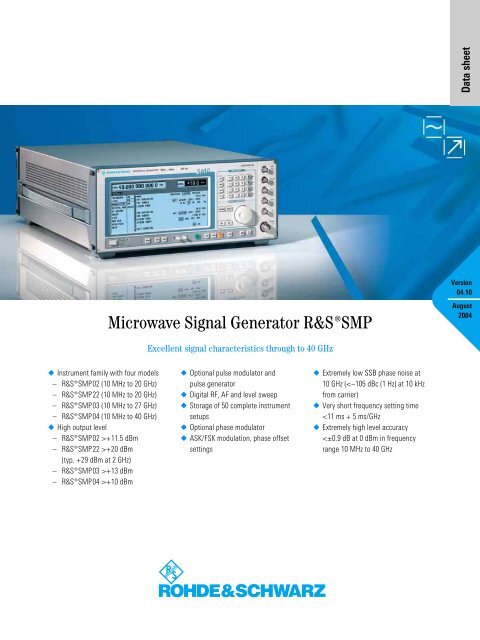
Microwave Signal Generator ¸SMP
Microwave Signal Generator ¸SMP
Microwave Signal Generator ¸SMP

You also want an ePaper? Increase the reach of your titles
YUMPU automatically turns print PDFs into web optimized ePapers that Google loves.
Data sheet<br />
Version<br />
04.10<br />
<strong>Microwave</strong> <strong>Signal</strong> <strong>Generator</strong> ¸SMP<br />
August<br />
2004<br />
Excellent signal characteristics through to 40 GHz<br />
◆ Instrument family with four models<br />
– ¸SMP02 (10 MHz to 20 GHz)<br />
– ¸SMP22 (10 MHz to 20 GHz)<br />
– ¸SMP03 (10 MHz to 27 GHz)<br />
– ¸SMP04 (10 MHz to 40 GHz)<br />
◆ High output level<br />
– ¸SMP02 >+11.5 dBm<br />
– ¸SMP22 >+20 dBm<br />
(typ. +29 dBm at 2 GHz)<br />
– ¸SMP03 >+13 dBm<br />
– ¸SMP04 >+10 dBm<br />
◆ Optional pulse modulator and<br />
pulse generator<br />
◆ Digital RF, AF and level sweep<br />
◆ Storage of 50 complete instrument<br />
setups<br />
◆ Optional phase modulator<br />
◆ ASK/FSK modulation, phase offset<br />
settings<br />
◆ Extremely low SSB phase noise at<br />
10 GHz (
<strong>Microwave</strong> signals in the range<br />
from 10 MHz to 40 GHz<br />
The basic models of the ¸SMP cover<br />
the following frequency ranges:<br />
◆ ¸SMP02/¸SMP22<br />
(2 GHz to 20 GHz)<br />
◆ ¸SMP03 (2 GHz to 27 GHz)<br />
◆ ¸SMP04 (2 GHz to 40 GHz)<br />
The lower frequency limit can be optionally<br />
extended to 10 MHz.<br />
A modern frequency synthesis concept<br />
with direct digital synthesis (DDS)<br />
ensures the following:<br />
◆ Stable output frequency<br />
◆ 0.1 Hz frequency resolution<br />
◆ Fast settling after a frequency<br />
change<br />
High, levelled output power<br />
All ¸SMP models have been<br />
designed for high output power without<br />
any compromises:<br />
◆ ¸SMP02 (>+11.5 dBm)<br />
◆ ¸SMP22 (>+20 dBm)<br />
◆ ¸SMP03 (>+13 dBm)<br />
◆ ¸SMP04 (>+10 dBm)<br />
The output levels specified are valid for<br />
the upper frequency limit.<br />
Excellent spectral purity<br />
High spectral purity is ensured by the use<br />
of YIG oscillators – up to 20 GHz without<br />
any frequency multiplying:<br />
◆ Harmonics<br />
typ. 1.8 GHz<br />
◆ Nonharmonics
Intelligent menu guidance for<br />
maximum ease of operation<br />
◆ Large-size LC display<br />
◆ Menu-guided operation with all menu<br />
levels being shown at a glance<br />
◆ Two menu memories to speed up<br />
operation<br />
User-friendly details<br />
◆ Digital RF, AF and level sweep<br />
◆ Storage of 50 complete instrument<br />
setups<br />
◆ Combination of any modulation<br />
modes possible<br />
◆ Ultra-low RF leakage<br />
◆ RF control output<br />
Unambiguous results due to<br />
high spectral purity<br />
Stable output frequency<br />
The crystal reference built-in as standard<br />
ensures an accurate and low-drift output<br />
frequency.<br />
The ¸SMP can also be fitted with an<br />
oven-controlled crystal oscillator (option<br />
¸SMP-B1, OCXO) to meet the most<br />
exacting requirements.<br />
High output level eliminates<br />
the need for add-on units<br />
A large number of microwave measurements<br />
requires mainly one thing: a high<br />
output level, which until now has only<br />
been possible with expensive add-on<br />
amplifiers.<br />
–40<br />
dBc<br />
–50<br />
Owing to their high output levels, the<br />
¸SMP models feature sufficient<br />
reserves for compensating the attenuation<br />
of long cables as well as the losses of<br />
power splitters and directional couplers.<br />
The ¸SMP22 achieves a level of up to<br />
29 dBm at 2 GHz and an excellent value<br />
of 23 dBm at 20 GHz.<br />
Our standard:<br />
0.1 Hz frequency resolution<br />
A high frequency resolution is required<br />
especially for scientific applications and<br />
in industrial research, e.g. for surface<br />
measurements of materials using radar<br />
equipment.<br />
The outstanding features of the<br />
¸SMP are the extremely low SSB<br />
phase noise of
The ¸SMP is setting standards with a<br />
resolution of 0.1 Hz throughout its frequency<br />
range, and even above 20 GHz.<br />
Variety of applications<br />
The ¸SMP is ideal for the following<br />
applications:<br />
◆ Substitution of local oscillators<br />
◆ Measurements on nonlinear components<br />
such as frequency multipliers or<br />
high-level mixers<br />
◆ Driving of travelling wave tubes<br />
(TWTs) and other power stages<br />
◆ Interconnection of several signal<br />
generators for intermodulation<br />
measurements<br />
◆ Tracking generator for spectrum and<br />
network analyzers<br />
High-quality shielding<br />
Sensitivity measurements on low-noise<br />
satellite receivers can only be made with<br />
absolutely RF-leakage-proof signal<br />
sources.<br />
The comprehensive shielding of the<br />
¸SMP ensures extremely low RF<br />
leakage.<br />
FSK modulation<br />
Owing to a special frequency control circuit,<br />
the precision FM/ϕM modulator features<br />
an extremely high carrier frequency<br />
accuracy and stability in the FM DC<br />
mode. Digital frequency shift keying (FSK<br />
modulation) is also possible. A deviation<br />
of up to 1 MHz (2 MHz above 20 GHz) can<br />
be selected.<br />
Wide ϕM modulation range<br />
The wide frequency range of the phase<br />
modulation extending from DC to 100 kHz<br />
allows testing of phase-sensitive circuits.<br />
¸SMP for use as a VCO<br />
In DC-coupled FM or ϕM mode, the<br />
¸SMP can also be used as a voltagecontrolled<br />
oscillator (VCO) and integrated<br />
into an external frequency control loop.<br />
The RF control output fitted on the rear<br />
panel is very useful for this application.<br />
¸SMP<br />
FM/ϕM<br />
modulator<br />
YIG<br />
2 GHz to 10 GHz<br />
YIG<br />
10 GHz to 20 GHz<br />
FM DC nonsynchronized<br />
(unlocked)<br />
The RF control output provides signals in<br />
the frequency range 2 GHz to 20 GHz and<br />
can, for example, be used for monitoring<br />
the output frequency with the aid of a<br />
frequency counter (FIG 3).<br />
Pulse modulation<br />
Ideal for radar receivers<br />
All data specified for pulse modulation,<br />
which is frequently used in the development,<br />
production and maintenance of<br />
radar receivers, is valid throughout the<br />
rated frequency range and also at the<br />
important intermediate frequencies of<br />
70 MHz and 140 MHz. The on/off ratio is<br />
better than 80 dB, the rise/fall time<br />
shorter than 10 ns. Pulse widths of less<br />
than 20 ns are possible (FIG 4).<br />
Optional pulse generator<br />
In addition to feeding in external modulation<br />
signals, the pulse generator (option<br />
¸SMP-B14) can also be used to gen-<br />
direct<br />
¸SMP 03/04<br />
1<br />
2 20 GHz to 40 GHz<br />
6 GHz<br />
2 GHz to 20 GHz<br />
10 MHz to 2 GHz<br />
¸SMP-B11<br />
RF<br />
out<br />
Frequency and phase modulation<br />
The ¸SMP is fitted as standard with a<br />
broadband FM modulator covering a<br />
modulation frequency range up to 5 MHz<br />
for deviations up to 10 MHz (20 MHz<br />
above 20 GHz).<br />
EXT1 or EXT2<br />
FIG 3: ¸SMP as a VCO<br />
DUT<br />
Frequency divider/<br />
phase comparator/<br />
control amplifier<br />
2 GHz to 20 GHz<br />
(RF control output)<br />
(2) (2)<br />
90 %<br />
In addition, a precision FM/ϕM modulator<br />
(option ¸SM-B5) with a modulation<br />
frequency range of up to 1 MHz and<br />
maximum deviation of up to 1 MHz<br />
(2 MHz for f >20 GHz) is available for<br />
testing communication receivers and for<br />
scientific applications.<br />
FIG 4: Pulse modulator, universally<br />
used in microwave<br />
applications such as radar;<br />
(1) shortest pulse duration<br />
20 ns,<br />
(2) typ. 3 ns rise/fall time,<br />
more than 80 dB on/off ratio<br />
(1)<br />
10 %<br />
50 %<br />
4 <strong>Microwave</strong> <strong>Signal</strong> <strong>Generator</strong> ¸SMP
erate internal single or double pulses<br />
with pulse frequencies up to 10 MHz.<br />
The pulse generator can also be triggered<br />
externally, pulse width and delay being<br />
user-selectable over a wide range.<br />
Simultaneous modulation<br />
modes and their application<br />
All modulation modes which the<br />
¸SMP is able to generate can be<br />
combined (in the case of the<br />
¸SMP03/04 with some restrictions<br />
regarding pulse and amplitude modulation).<br />
Highly complex signals can thus be<br />
generated for modern communication<br />
and radar systems.<br />
Doppler effects<br />
The combination of pulse modulation and<br />
FM DC simulates Doppler effects and also<br />
chirp signals.<br />
Pulse radar with rotating antenna<br />
Combined scan and pulse modulation<br />
provides the type of signals occurring in<br />
pulse radar applications with rotating<br />
antenna.<br />
In the example shown in FIG 5, the external<br />
pulse from the pulse generator or<br />
radar display is applied to the external<br />
pulse input of the ¸SMP and used as<br />
Pulsed transmitter<br />
Pulse generator<br />
Display<br />
LO<br />
Circulator<br />
Antenna direction pulse<br />
RF<br />
1<br />
Sideband<br />
filter<br />
a trigger for the internal pulse generator<br />
and modulator.<br />
The main advantage of this kind of trigger<br />
is that it can be delayed to simulate<br />
distance and direction and to check the<br />
values on the display.<br />
Fading<br />
Simultaneous frequency and amplitude<br />
modulation can be used to study fading<br />
effects of FM receivers.<br />
Sweep capabilities<br />
Level sweep<br />
The 20 dB level sweep of the ¸SMP is<br />
an efficient function for determining<br />
power characteristics and for compression<br />
measurements.<br />
Digital frequency sweep<br />
The digital frequency sweep with steps<br />
from 10 ms is a useful facility for measuring<br />
the frequency response of microwave<br />
modules or antennas.<br />
Sweep modes<br />
The digital sweep can be executed automatically<br />
in repetitive mode or in singleshot<br />
mode with selectable sweep time.<br />
Manual sweeping (STEP MODE) within<br />
the sweep limits is also possible. Trigger<br />
Pulse<br />
FIG 5: Radar tests (switch position 1 for testing the distance indicated by radar,<br />
switch position 2 for testing the antenna direction indicated by radar)<br />
2<br />
inputs and outputs facilitate synchronous<br />
operation in conjunction with other<br />
instruments.<br />
Use in EMC measurements<br />
Functions qualifying the ¸SMP for<br />
EMC applications include the trigger<br />
facility for step-by-step sweeping, marker<br />
outputs and, above all, the extension of<br />
the frequency range to 10 MHz (option<br />
¸SMP-B11).<br />
The capability of compensating external<br />
frequency responses is also an important<br />
feature.<br />
Frequency hopping in list mode<br />
One of the very special features of the<br />
¸SMP is the list mode. Unlike the<br />
normal sweep mode with increasing or<br />
decreasing frequencies, the list mode can<br />
be used for programming frequency hopping.<br />
A list editor makes programming<br />
extremely easy. Up to 2003 pairs of<br />
frequency and level values can be stored<br />
in lists.<br />
Of course, the same types of sweep can<br />
be executed in the list mode as in the<br />
normal sweep mode.<br />
Frequency response<br />
compensation<br />
Power amplifiers, cables, antennas and<br />
TEM cells usually exhibit a relatively large<br />
frequency response which has to be compensated<br />
to obtain accurate measurement<br />
results.<br />
The ¸SMP provides two excellent<br />
tools for the correction of external<br />
frequency responses:<br />
◆ User-defined correction of external<br />
frequency responses<br />
◆ External level control using a power<br />
meter<br />
<strong>Microwave</strong> <strong>Signal</strong> <strong>Generator</strong> ¸SMP 5
User-defined correction of external<br />
frequency responses<br />
The user correction function is extremely<br />
useful for fast RF sweeps, for example to<br />
compensate nonlinearities of an amplifier.<br />
Power amplifier<br />
Horn antenna<br />
DUT<br />
The known frequency response can be<br />
compensated by entering level correction<br />
values for up to 160 frequency points. The<br />
correction values for the frequencies<br />
between these points are determined by<br />
means of automatic interpolation (FIG 6).<br />
5<br />
5<br />
5<br />
3<br />
3 5<br />
5<br />
5<br />
In addition, the ¸SMP can automatically<br />
measure the level correction values<br />
at a keystroke with the aid of external<br />
power meters such as the ¸NRVS or<br />
¸NRVD.<br />
FIG 6: Output level with frequency response correction ON (yellow curve) and OFF (orange curve)<br />
External level control using a<br />
power meter<br />
A very simple method is the external level<br />
control with high level accuracy (FIG 7).<br />
V/GHz<br />
EXT ALC<br />
DC FREQ<br />
DC<br />
<strong>Signal</strong> <strong>Generator</strong> ¸SMP<br />
RF<br />
Power Meter ¸NRVS<br />
DUT<br />
Power splitter<br />
Power Sensor<br />
¸NRV-Z15<br />
FIG 7: External level control for the <strong>Microwave</strong> <strong>Signal</strong> <strong>Generator</strong> ¸SMP<br />
Scalar network analysis<br />
¸FSP + ¸FSP-B10<br />
The <strong>Microwave</strong> <strong>Signal</strong> <strong>Generator</strong><br />
¸SMP used as a tracking generator<br />
in conjunction with the Spectrum<br />
Analyzer ¸FSP and the option<br />
¸FSP-B10 provides a unique scalar<br />
network analysis function. This application<br />
features an extremely wide dynamic<br />
range, which allows, for example, filter<br />
resonances in the stop band to be<br />
displayed at very low levels.<br />
Due to the user-definable frequency<br />
offset, measurements on frequencyconverting<br />
devices can also be performed<br />
with this configuration.<br />
REF 10 MHz<br />
GPIB<br />
Trigger<br />
Blanking signal<br />
Aux<br />
Aux<br />
Blank<br />
Trigger<br />
¸SMP<br />
FIG 8: Scalar network analysis with the <strong>Microwave</strong> <strong>Signal</strong> <strong>Generator</strong> ¸SMP and the<br />
Spectrum Analyzer ¸FSP with option ¸FSP-B10<br />
DUT<br />
6 <strong>Microwave</strong> <strong>Signal</strong> <strong>Generator</strong> ¸SMP
Menu memories<br />
Frequently used menu settings can be<br />
stored in two memories and recalled at a<br />
keystroke.<br />
The FM modulation menu shows the clear-cut representation of selectable parameters and current<br />
instrument status. Each setting can be made quickly and easily by means of the spinwheel and a few<br />
keys.<br />
FIG 11: Storage of menu settings<br />
Automatic measurement<br />
functions for production and<br />
test labs<br />
The memory sequence is an extremely<br />
useful function. It provides convenient<br />
execution of standard test routines or frequently<br />
required sequences of different<br />
types of single measurements.<br />
Up to 50 complete instrument setups can<br />
be stored. After programming the<br />
sequence of measurements to be executed,<br />
the user can activate the autorun<br />
control facility.<br />
Remote control to SCPI standard<br />
The IEC/IEEE-bus remote control commands<br />
are in line with the SCPI guidelines.<br />
One of the advantages is that the<br />
user can exchange measuring instruments<br />
in an automatic system without<br />
having to modify the control software.<br />
Intelligent operating concept<br />
Easy-to-follow menus<br />
Neither multifunction keys nor obscure<br />
special functions burden the user. All<br />
functions are clearly arranged in menus.<br />
Menus and functions as well as parameter<br />
settings can be conveniently selected<br />
with a spinwheel.<br />
Easy-to-read screen display<br />
All settings associated with a certain<br />
function can be seen at a glance on the<br />
large-size, high-contrast LC display.<br />
HELP function<br />
Explanatory remarks can be called up for<br />
each individual menu. This does away<br />
with wasting time in looking up functions<br />
in a manual.<br />
FIG 12: Online help<br />
FIG 9: SAVE and RCL for storing and recalling<br />
settings<br />
This function also allows synchronous<br />
operation with other units through triggering.<br />
Step times can be separately<br />
programmed for each step.<br />
FIG 10: General settings and menu selection<br />
with spinwheel, RETURN, SELECT and arrow<br />
keys<br />
<strong>Microwave</strong> <strong>Signal</strong> <strong>Generator</strong> ¸SMP 7
Expertise in microwaves<br />
Continuity of progress at<br />
Rohde&Schwarz<br />
The name of Rohde&Schwarz is also<br />
synonymous with quality in the field of<br />
microelectronics.<br />
Large investments have been made in<br />
advanced technologies to fully keep up<br />
with the ever increasing demands made<br />
on the precision and reliability of microwave<br />
modules. Rohde&Schwarz uses<br />
ultra-modern clean rooms and systems for<br />
the development and production of thinfilm<br />
circuits.<br />
Airbridges is an ideal technique for implementing<br />
PCB crossovers with excellent highfrequency<br />
characteristics. The photo above<br />
has been taken with a scanning electron<br />
microscope and shows such an airbridge<br />
which is only 0.05 mm long.<br />
8 <strong>Microwave</strong> <strong>Signal</strong> <strong>Generator</strong> ¸SMP
Specifications<br />
Frequency<br />
Range (standard)<br />
¸SMP02/¸SMP22<br />
¸SMP03<br />
¸SMP04<br />
Range (with option ¸SMP-B11)<br />
¸SMP02/¸SMP22<br />
¸SMP03<br />
¸SMP04<br />
Resolution<br />
2 GHz to 20 GHz<br />
2 GHz to 27 GHz<br />
2 GHz to 40 GHz<br />
10 MHz to 20 GHz<br />
10 MHz to 27 GHz<br />
10 MHz to 40 GHz<br />
0.1 Hz<br />
Setting time (to within
Maximum level 4) ¸SMP03/SMP04 (with options ¸SMP-B12/-B13)<br />
Frequency range<br />
¸SMP03<br />
Pulse modulation<br />
off<br />
10 MHz to +10 dBm<br />
Pulse modulation<br />
on<br />
¸SMP04<br />
Pulse modulation<br />
off<br />
Pulse modulation<br />
on<br />
2 to 20/27/40 GHz same as max. level without options ¸SMP-B12/-B13<br />
Minimum level of all models<br />
Without option ¸SMP-B15/-B17<br />
With option ¸SMP-B15/-B17<br />
Resolution<br />
–20 dBm<br />
–130 dBm<br />
0.1 dB or 0.01 dB<br />
Total accuracy 3)5) (frequency response and temperature effect included)<br />
Frequency range Level Accuracy<br />
10 MHz to +10 dBm<br />
>–10 dBm<br />
>–60 dBm<br />
≤–60 dBm<br />
2 GHz to 20 GHz >+10 dBm<br />
>–10 dBm<br />
>–60 dBm<br />
≤–60 dBm<br />
>20 GHz to 27/40 GHz >+10 dBm<br />
>–10 dBm<br />
>–60 dBm<br />
≤–60 dBm<br />
Output impedance 1)2)3)4)5)<br />
VSWR<br />
f ≤20 GHz<br />
f >20 GHz<br />
Setting time<br />
(after IEC/IEEE-bus delimiter)<br />
With option ¸SMP-B15/-B17,<br />
with switching in attenuator set<br />
Non-interrupting level setting<br />
(ATTENUATOR MODE FIXED)<br />
Setting range<br />
Simultaneous modulation<br />
Linear amplitude modulation<br />
Operating modes<br />
50 Ω<br />
Phase modulation with option ¸SM-B5<br />
Operating modes<br />
Maximum deviation<br />
f ≤20 GHz<br />
f >20 GHz<br />
Resolution<br />
f ≤20 GHz<br />
f >20 GHz<br />
Setting accuracy at AF = 1 kHz<br />
f ≤20 GHz<br />
f >20 GHz<br />
internal, external AC/DC, two-tone<br />
with two separate channels ϕM1 and<br />
ϕM2<br />
10 rad<br />
20 rad<br />
ϕM distortion at AF = 1 kHz and<br />
5 rad deviation
LF generator option ¸SM-B2<br />
Waveforms<br />
Frequency range<br />
Sinewave, noise<br />
Triangular, squarewave<br />
Resolution<br />
sinewave, triangular, squarewave,<br />
noise<br />
0.1 Hz to 500 kHz<br />
0.1 Hz to 50 kHz<br />
0.1 Hz<br />
Frequency accuracy
Auxiliary interface with option ¸SMP-B18<br />
V/GHz output<br />
Z output<br />
Remote control<br />
System<br />
output voltage proportional to frequency,<br />
0.5 V/GHz 9) or 1 V/GHz selectable<br />
user-selectable level range<br />
–10 V to +10 V<br />
IEC625 (IEEE488)<br />
Command set SCPI 1992.0<br />
Connector<br />
IEC/IEEE-bus address 0 to 30<br />
Interface functions<br />
General data<br />
Power supply<br />
Electromagnetic compatibility<br />
24-contact Amphenol<br />
SH1, AH1, T6, L4, SR1, RL1, PP1, DC1,<br />
DT1, C0<br />
90 V to 132 V (AC), 47 Hz to 440 Hz<br />
180 V to 265 V (AC), 47 Hz to 440 Hz<br />
autoranging, max. 400 VA<br />
safety class I to VDE 0411 (IEC348)<br />
Standards adhered to postal regulation 243/1991<br />
EN55011 (VDE 0875 T11), class B<br />
VDE 0875, suppression level K<br />
MIL-STD-461B<br />
– RE02 radiated emissions<br />
– CE03 conducted emissions<br />
– CS01/02 conducted susceptibility<br />
RF leakage (f
Ordering information<br />
Designation Type Order No.<br />
<strong>Microwave</strong> <strong>Signal</strong> <strong>Generator</strong> ¸SMP02 1035.5005.02<br />
<strong>Microwave</strong> <strong>Signal</strong> <strong>Generator</strong> ¸SMP22 1035.5005.22<br />
<strong>Microwave</strong> <strong>Signal</strong> <strong>Generator</strong> ¸SMP03 1035.5005.03<br />
<strong>Microwave</strong> <strong>Signal</strong> <strong>Generator</strong> ¸SMP04 1035.5005.04<br />
Accessories supplied<br />
For ¸SMP02/22/03<br />
For ¸SMP04<br />
Options<br />
power cable, operating manual<br />
female adapter 3.5 mm<br />
female adapter 2.9 mm<br />
OCXO Reference<br />
Oscillator ¸SMP-B1 1036.5109.02<br />
Frequency Extension<br />
0.01 GHz to 2 GHz 1) ¸SMP-B11 1036.6240.02<br />
Pulse Modulator<br />
2 GHz to 20 GHz<br />
(¸SMP02, ¸SMP22) 1) ¸SMP-B12<br />
2 GHz to 27 GHz<br />
(¸SMP03) 1)<br />
¸SMP-B12<br />
2 GHz to 40 GHz<br />
(¸SMP04) 1)<br />
¸SMP-B12<br />
0.01 GHz to 2 GHz 1) ¸SMP-B13<br />
1036.5750.02<br />
1036.5750.03<br />
1036.5750.04<br />
1036.7147.02<br />
Pulse <strong>Generator</strong> ¸SMP-B14 1036.7347.02<br />
RF Attenuator<br />
27 GHz (¸SMP02,<br />
¸SMP22, ¸SMP03) 1) ¸SMP-B15<br />
40 GHz (¸SMP04) 1) ¸SMP-B17<br />
1036.5250.02<br />
1036.5550.02<br />
Auxiliary Interface ¸SMP-B18 1036.8920.02<br />
Rear Connectors for<br />
RF, AF<br />
¸SMP02, ¸SMP22,<br />
¸SMP03 1)<br />
¸SMP04 1)<br />
¸SMP-B19<br />
¸SMP-B20<br />
1039.4303.02<br />
1039.4503.02<br />
LF <strong>Generator</strong> ¸SM-B2 1036.7947.02<br />
FM/ϕM Modulator ¸SM-B5 1036.8489.02<br />
19" Rack Adapter ¸ZZA-94 0396.4905.00<br />
Extras<br />
Service Kit ¸SM-Z3 1085.2500.02<br />
Trolley ¸ZZK-1 1014.0510.00<br />
Transit Case ¸ZZK-945 1013.9372.00<br />
Adapter (¸SMP02,<br />
¸SMP22, ¸SMP03)<br />
3.5 mm, female<br />
3.5 mm, male<br />
N, female<br />
N, male<br />
1)<br />
Designation Type Order No.<br />
Adapter (¸SMP04)<br />
2.9 mm, female<br />
2.9 mm, male<br />
N, female<br />
N, male<br />
Factory-fitted option.<br />
1021.0512.00<br />
1021.0529.00<br />
1021.0535.00<br />
1021.0541.00<br />
1036.4790.00<br />
1036.4802.00<br />
1036.4777.00<br />
1036.4783.00<br />
More information at<br />
www.rohde-schwarz.com<br />
(search term: SMP)<br />
Certified Quality System<br />
ISO 9001<br />
DQS REG. NO 1954 QM<br />
Certified Environmental System<br />
ISO 14001<br />
DQS REG. NO 1954 UM<br />
www.rohde-schwarz.com<br />
R&S® is a registered trademark of Rohde&Schwarz GmbH&Co. KG · Trade names are trademarks of the owners · Printed in Germany (Pe sk)<br />
0758.0951.32 · ¸SMP · Version 04.10 · August 2004 · Data without tolerance limits is not binding · Subject to change