Policy Update - Design and Manufacture of Surf Boats
Policy Update - Design and Manufacture of Surf Boats
Policy Update - Design and Manufacture of Surf Boats

You also want an ePaper? Increase the reach of your titles
YUMPU automatically turns print PDFs into web optimized ePapers that Google loves.
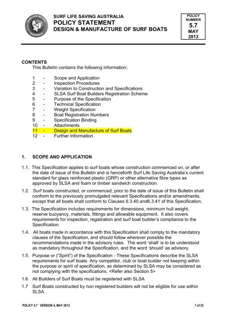
SURF LIFE SAVING AUSTRALIA<br />
POLICY STATEMENT<br />
DESIGN & MANUFACTURE OF SURF BOATS<br />
POLICY<br />
NUMBER<br />
5.7<br />
MAY<br />
2013<br />
CONTENTS<br />
This Bulletin contains the following information;<br />
1 - Scope <strong>and</strong> Application<br />
2 - Inspection Procedures<br />
3 - Variation to Construction <strong>and</strong> Specifications<br />
4 - SLSA <strong>Surf</strong> Boat Builders Registration Scheme<br />
5 - Purpose <strong>of</strong> the Specification<br />
6 - Technical Specification<br />
7 - Weight Specification<br />
8 - Boat Registration Numbers<br />
9 - Specification Binding<br />
10 - Attachments<br />
11 - <strong>Design</strong> <strong>and</strong> <strong>Manufacture</strong> <strong>of</strong> <strong>Surf</strong> <strong>Boats</strong><br />
12 - Further Information<br />
1. SCOPE AND APPLICATION<br />
1.1. This Specification applies to surf boats whose construction commenced on, or after<br />
the date <strong>of</strong> issue <strong>of</strong> this Bulletin <strong>and</strong> is henceforth <strong>Surf</strong> Life Saving Australia’s current<br />
st<strong>and</strong>ard for glass reinforced plastic (GRP) or other alternative fibre types as<br />
approved by SLSA <strong>and</strong> foam or timber s<strong>and</strong>wich construction.<br />
1.2. <strong>Surf</strong> boats constructed, or commenced, prior to the date <strong>of</strong> issue <strong>of</strong> this Bulletin shall<br />
conform to the previously promulgated relevant Specifications <strong>and</strong>/or amendments,<br />
except that all boats shall conform to Clauses 6.3.40.<strong>and</strong>6.3.41 <strong>of</strong> this Specification.<br />
1.3. The Specification includes requirements for dimensions, minimum hull weight,<br />
reserve buoyancy, materials, fittings <strong>and</strong> allowable equipment. It also covers<br />
requirements for inspection, registration <strong>and</strong> surf boat builder’s compliance to the<br />
Specification.<br />
1.4. All boats made in accordance with this Specification shall comply to the m<strong>and</strong>atory<br />
clauses <strong>of</strong> the Specification, <strong>and</strong> should follow wherever possible the<br />
recommendations made in the advisory rules. The word ‘shall’ is to be understood<br />
as m<strong>and</strong>atory throughout the Specification, <strong>and</strong> the word ‘should’ as advisory.<br />
1.5. Purpose or (“Spirit”) <strong>of</strong> the Specification - These Specifications describe the SLSA<br />
requirements for surf boats. Any competitor, club or boat builder not keeping within<br />
the purpose or spirit <strong>of</strong> specification, as determined by SLSA may be considered as<br />
not complying with the specifications. <br />
1.6 All Builders <strong>of</strong> <strong>Surf</strong> <strong>Boats</strong> must be registered with SLSA<br />
1.7 <strong>Surf</strong> <strong>Boats</strong> constructed by non registered builders will not be eligible for use within<br />
SLSA<br />
POLICY 5.7 VERSION 4, MAY 2013 1 <strong>of</strong> 23
2. INSEPECTION PROCEDURERS<br />
2.1. <strong>Surf</strong> boats shall only be eligible to have a Compliance Label <strong>and</strong> Registration<br />
Number if constructed in accordance with the current Specifications. The registered<br />
boat builder shall have quality control procedures in practice that ensure the<br />
compliance to this specification <strong>and</strong> SLSA requirements.<br />
2.2. SLSA appoints National <strong>Surf</strong> Boat Inspectors who have the authority, at any time, to<br />
inspect boats during their construction, witness the application <strong>of</strong> Compliance Labels<br />
<strong>and</strong> stamping <strong>of</strong> Registration Numbers, witness the signatures on Certificate <strong>of</strong> Initial<br />
Inspection <strong>and</strong> Registration Form, or check records <strong>and</strong> other relevant duties as<br />
requested by SLSA. The forms are available from SLSA but are normally in the<br />
possession <strong>of</strong> the National Inspectors. A Copy <strong>of</strong> this form is appended to this<br />
Specification, (Form No. 31/2001).<br />
2.3. It is the responsibility <strong>of</strong> the National Boat Inspectors should, wherever possible<br />
check, by r<strong>and</strong>om visitation <strong>and</strong> liaison, that boats built (or noticed competing) within<br />
their area, comply with the current requirements. Any known departure from the<br />
Specification shall be also reported to SLSA <strong>and</strong> the club purchasing the boat. <strong>Boats</strong><br />
built outside the current requirements shall not be permitted to compete at SLSA<br />
sanctioned competitions.<br />
2.4. M<strong>and</strong>atory Inspections—<strong>Boats</strong> being built in an Application for Registration<br />
procedure require a series <strong>of</strong> m<strong>and</strong>atory inspections by National Boat Inspectors<br />
<strong>and</strong>/or an appointed panel (see Clauses 4.3 <strong>and</strong> 4.4) who shall submit the panel’s<br />
report through the Hon. National Boat Officer to SLSA for final decision. Similarly,<br />
boats classed as experimental shall be subject to a series <strong>of</strong> inspections (as<br />
determined by SLSA) during their construction <strong>and</strong> testing before final approval (see<br />
Clauses 3.3 <strong>and</strong> 3.4).<br />
2.5. Inspection Records—National Inspectors undertaking the m<strong>and</strong>atory inspections, for<br />
either a Builder’s Registration application or an experimental boat construction, shall<br />
use SLSA Certificate <strong>of</strong> Initial Inspection <strong>and</strong> Registration Form, for recording<br />
construction progress but shall omit the final witnessing <strong>and</strong> application <strong>of</strong><br />
Compliance Label <strong>and</strong> stamping or engraving <strong>of</strong> the boats Registration Number until<br />
final approval by SLSA.<br />
2.6. Builders Quality System—Under the conditions <strong>of</strong> the Official Agreement <strong>of</strong><br />
Registration the Registered Boat Builder has an obligation <strong>and</strong> is responsible for the<br />
quality control <strong>and</strong> assurance that the boat is built to the Specification. Therefore the<br />
builder, once registered, shall then be fully responsible for final certification <strong>of</strong><br />
compliance, including weighing, the application <strong>of</strong> the Compliance Label <strong>and</strong> the<br />
stamping or engraving <strong>of</strong> the Registration Number. The boat shall not leave the Boat<br />
Builder’s premises until complete <strong>and</strong> certified as compliant.<br />
3. VARITATION TO CONSTRUCTION AND SPECIFICATIONS<br />
3.1. Deviation to the Specification—SLSA, upon the recommendation <strong>of</strong> the National<br />
Competition Manager <strong>and</strong>/or the Hon. National <strong>Surf</strong> Boat Officer, may allow a<br />
deviation to build a boat outside the SLSA Specification, subject to Clauses 3.2 <strong>and</strong><br />
3.3 <strong>of</strong> the Specification.<br />
POLICY 5.7 VERSION 4, MAY 2013 2 <strong>of</strong> 23
3.2. Experimental <strong>Boats</strong>—Before SLSA approval for the deviation, a detailed submission<br />
<strong>of</strong> the design, material <strong>and</strong> the construction methods to be used, shall be submitted<br />
to the Hon. National <strong>Surf</strong> Boat Officer for investigation <strong>and</strong> opinion. One boat may<br />
then be allowed to be constructed, which shall include a series <strong>of</strong> SLSA inspections,<br />
<strong>and</strong> it shall be classed as experimental under these conditions. Experimental <strong>Boats</strong><br />
shall not be used in any SLSA Competition unless specifically allowed by SLSA’s<br />
Competition Manager <strong>and</strong>/or the Director <strong>of</strong> Competition after due consultation with<br />
the Hon. National <strong>Surf</strong> Boat Officer.<br />
3.3. Experimental Testing Period—It shall be m<strong>and</strong>atory for an experimental boat to<br />
undergo an extensive testing period, under varying conditions as determined by<br />
SLSA, before a final decision on approval or other recommendations will be given by<br />
SLSA to alter the Specification.<br />
3.4. Conditional Approval <strong>of</strong> Experimental <strong>Boats</strong>—SLSA approval <strong>of</strong> the development,<br />
building <strong>and</strong> trialing <strong>of</strong> an experimental boat is conditional in that SLSA <strong>and</strong> the<br />
association in general will not be responsible for any expenses incurred. Further, the<br />
issue <strong>of</strong> experimental status is no guarantee <strong>of</strong> the said boat being guaranteed final<br />
approval.<br />
3.5. Specification Alteration Proposals—Any proposal to alter the Specification (including<br />
results <strong>of</strong> experimental testing) shall be submitted to the Hon. National <strong>Surf</strong> Boat<br />
Officer for evaluation <strong>and</strong> endorsement <strong>of</strong> SLSA before implementation is permitted.<br />
This requirement includes any change in basic design contemplated by the Boat<br />
Builder.<br />
3.6. National Meetings—The Hon. National <strong>Surf</strong> Boat Officer in conjunction with the<br />
National Competitions Manager, may convene meetings to consider <strong>and</strong> evaluate<br />
proposed changes or additions to the existing Specification.<br />
3.7. Meeting Participants—The meetings shall, in general, comprise appropriate National<br />
Boat Inspectors, State Boat Officers, Registered Boat Builders <strong>and</strong> other competent<br />
persons as co-opted by the Hon. National Officer or National Competitions Manager.<br />
4. SLSA SURF BOAT BUILDERS REGISTRATION SCHEME<br />
4.1. Applicant to apply in writing to SLSA, outlining company name, company principal,<br />
address, contact numbers, company background or pr<strong>of</strong>ile, <strong>and</strong> details <strong>of</strong> boat to be<br />
built. An initial (non refundable) registration fee <strong>of</strong> $500 is to accompany the initial<br />
application.<br />
4.2. On receipt <strong>of</strong> the above application, the applicant will be advised in writing that they<br />
shall supply a detailed test panel <strong>of</strong> the proposed layup <strong>and</strong> that they will be required<br />
to build one boat for inspection by the Hon. National <strong>Surf</strong> Boat Officer (or nomineesthe<br />
National Boat Inspectors). The applicant will also be issued with a copy <strong>of</strong><br />
current relevant SLSA Specifications.<br />
4.3. On advance notice from the Builder that the construction is to commence, SLSA will<br />
arrange for initial inspection <strong>of</strong> the boat moulds <strong>and</strong> construction procedure, by<br />
National Boat Inspectors (or nominee), to check that the Specifications have been<br />
met. Additional inspections at appropriate intervals will be carried out in accordance<br />
with the SLSA requirements. The series <strong>of</strong> inspections shall be reported on a<br />
Certificate <strong>of</strong> Initial Inspection <strong>and</strong> Registration Form (Form No 31/2001).<br />
4.4. On completion, the builder shall present the boat to an SLSA panel <strong>of</strong> National Boat<br />
Inspectors (or SLSA nominees) for final inspection <strong>of</strong> compliance. The panel shall<br />
POLICY 5.7 VERSION 4, MAY 2013 3 <strong>of</strong> 23
make a report, to the Hon. National <strong>Surf</strong> Boat Officer, for the recommendation to<br />
SLSA for registration or the need for further evaluation for an agreed period.<br />
4.5. Following the inspections, the Builder will be advised in writing <strong>of</strong> the outcome <strong>of</strong> the<br />
Application for Registration. The outcome <strong>of</strong> the application cannot be assumed until<br />
written confirmation has been received by the Builder from SLSA.<br />
4.6. If successful, an Official Agreement will then be forwarded to the Builder for their<br />
signature. Builders cannot manufacture or sell items purporting to comply to SLSA<br />
Specifications until the agreement has been signed <strong>and</strong> returned to SLSA. The<br />
builder will then be a Registered SLSA <strong>Surf</strong> Boat Builder.<br />
4.7. Builders applying for re-registration may continue to manufacture boats <strong>and</strong> or sell<br />
items while a new agreement is being signed.<br />
4.8. If registration is not approved, the Builder will be notified by SLSA <strong>of</strong> the reasons <strong>and</strong><br />
what action that should be taken in order that registration may be reconsidered.<br />
4.9. The Builder is then required (if successful) to purchase from SLSA, Compliance<br />
Labels ($150 each) to be glassed under the surface <strong>of</strong> all boats manufactured to the<br />
SLSA Specifications. This label shall be located inside <strong>of</strong> the hull, port side, forward<br />
<strong>of</strong> bow rowlock, just below the gunwale.<br />
4.10. Compliance Labels are numbered (Registration Number) <strong>and</strong> stamped with the<br />
Builder’s name. The Builder is also required to mark the label with the date <strong>of</strong><br />
manufacture completion (month <strong>and</strong> year). The builder shall also stamp Initials, this<br />
date <strong>and</strong> the Registration Number solidly into the inner gunwale (see Clause 8.)<br />
located between the quarter bar <strong>and</strong> the stern bulkhead (or engrave directly, or glue<br />
<strong>and</strong> engraved or stamped plate to GRP). Further, the Builder is required to keep an<br />
up-to-date record for each boat <strong>of</strong> all numbers in sequence, boat type, colour, the<br />
finished bare structural condition weight, <strong>and</strong> the name <strong>and</strong> address <strong>of</strong> the<br />
purchaser.<br />
4.11. Annual re-registration will occur on 30th September <strong>of</strong> each year at which time an<br />
agreement will be forwarded by SLSA to each Builder. A re-registration fee <strong>of</strong> $200<br />
(non-refundable) must accompany the agreement when returned to SLSA. If the<br />
agreement <strong>and</strong> fee is not received by SLSA in 30 days, the Builder’s agreement will<br />
become null <strong>and</strong> void. Inactive Boat Builders have a period <strong>of</strong> two years in which<br />
they can re-register by paying the re-registration fee <strong>of</strong> $200. Should this two year<br />
period lapse, the Builder must again pay the $500 initial non-refundable registration<br />
fee <strong>and</strong> proceed through the original registration process in becoming an SLSA<br />
Registered Builder.<br />
4.12. Penalties for non-compliance with SLSA Specifications (also see Agreement) will be<br />
determined by SLSA after consideration <strong>of</strong> the circumstances <strong>of</strong> the non-compliance,<br />
<strong>and</strong> may result in cancellation <strong>of</strong> registration. The procedures in dealing with noncompliance<br />
are:<br />
(a) A letter from SLSA will be sent asking the Builder to explain their actions to SLSA<br />
in writing.<br />
(b) A panel consisting <strong>of</strong> the SLSA Chief Executive Officer, the Director <strong>of</strong><br />
Competition <strong>and</strong> the Hon. National <strong>Surf</strong> Boat Officer (or their nominees) will<br />
adjudicate on each non-compliance matter separately <strong>and</strong> on their merits, as<br />
may be required.<br />
4.13. The Builder should be aware that an authorised SLSA representative shall be<br />
entitled at all times during normal working hours to have necessary access to the<br />
Builder’s premises to inspect boats, moulds, the construction process <strong>and</strong> the Boat<br />
POLICY 5.7 VERSION 4, MAY 2013 4 <strong>of</strong> 23
Construction Register. This is necessary to ensure that boats which have been<br />
constructed, or are in the course <strong>of</strong> construction, comply with the conditions as<br />
required in this Specification or additional SLSA rulings <strong>and</strong> requirements.<br />
4.14. Builders will be placed on the SLSA national mailing list <strong>and</strong> will receive club mail in<br />
order to keep abreast <strong>of</strong> current matters within SLSA.<br />
4.15. The above registration <strong>and</strong> compliance fees may be varied by SLSA as deemed<br />
necessary <strong>and</strong> will be notified to Builders prior to implementation.<br />
4.16. <strong>Boats</strong> built by Registered Builders <strong>and</strong> not bearing the “SLSA Compliance Label”<br />
will not be permitted to participate in SLSA competitions/activity.<br />
5. PURPOSE OF THE SPECIFICACTION<br />
5.1 The purpose <strong>of</strong> these specifications are to describe SLSA requirements for surf boats<br />
<strong>and</strong> to ensure that all surf boats used within SLSA comply with the specifications <strong>and</strong><br />
with the spirit <strong>of</strong> the specifications.<br />
5.2 These specifications refer to boats used in SLSA <strong>and</strong> will be used by SLSA Officials<br />
to determine the eligibility, or otherwise, <strong>of</strong> a surf boat.<br />
5.3 Any competitor, or club, who attempts to win a race by any other than honorable<br />
means may be disqualified. This includes the use <strong>of</strong> boat not meeting the<br />
requirements <strong>of</strong> the appropriate SLSA specifications.<br />
5.4 Builders have an obligation to SLSA to ensure that all boats manufactured comply<br />
with the appropriate specifications.<br />
5.5 Clubs/competitors have a responsibility to ensure boats remain within specification.<br />
5.6 When a change in basic design is contemplated, Builders shall first seek the advice<br />
<strong>of</strong> the National <strong>Surf</strong> Boat Officer or his/her nominee as assigned by <strong>Surf</strong> Life Saving<br />
Australia.<br />
6. TECHNICAL SPECIFICATION<br />
6.1 GENERAL<br />
6.1.1. Boat builders commencing construction <strong>of</strong> Composite foam s<strong>and</strong>wich boats for the<br />
first time shall submit a test panel as directed by the Hon. National <strong>Surf</strong> Boat Officer<br />
<strong>of</strong> the proposed layup with full details to the Hon. National <strong>Surf</strong> Boat Officer.<br />
6.1.2. Any proposed changes or alternatives to approved layups, stiffening or construction<br />
shall be submitted prior to construction, along with supporting pr<strong>of</strong>essional<br />
engineering calculations <strong>and</strong> advice, for the consideration <strong>and</strong> approval <strong>of</strong> the Hon.<br />
National <strong>Surf</strong> Boat Officer. As a minimum requirement, the layups shall be at least<br />
as strong (e.g. equal or greater reinforcement fabric weight <strong>and</strong> improved fibre<br />
orientation) as the presently approved layups in the Specification.<br />
6.1.3. All components <strong>and</strong> items listed in HULL CONSTRUCTION (Clause 6.3.) shall be<br />
fitted to the boat unless described as advisory or where an otherwise SLSA<br />
approved alternative is allowed.<br />
POLICY 5.7 VERSION 4, MAY 2013 5 <strong>of</strong> 23
6.2. DIMENSIONS<br />
6.2.1. Length Overall – Minimum 6.86m to a maximum 7.925m (not including the sweep<br />
outrigger).<br />
6.2.2. Beam – Minimum <strong>of</strong> 1.62m between projections <strong>of</strong> outside hull at top <strong>of</strong> gunwale,<br />
measured at widest midship section near to Nos. 2 or 3 thwart; see also Clause<br />
6.2.4.<br />
6.2.3. Moulded depth – Minimum <strong>of</strong> 558mm from top <strong>of</strong> gunwale to lowest part <strong>of</strong> outside<br />
hull at keel, measured at the same section as the beam measurement.<br />
6.2.4. Hull reverse curvature – Any reverse curvature <strong>of</strong> the hull, between the stern <strong>and</strong> a<br />
point 3.04m from the bow, shall be limited to a maximum <strong>of</strong> 13mm, measured<br />
between gunwale <strong>and</strong> keel. Where the gunwale has been moulded, or where the<br />
outside hull at top <strong>of</strong> the gunwale is otherwise hard to measure, the reverse<br />
curvature may be measured by placing a straight edge batten over the hull with the<br />
top end <strong>of</strong> the straight edge within 5mm <strong>of</strong> the gunwale. A projection <strong>of</strong> the straight<br />
edge to the top <strong>of</strong> the gunwale must also comply with minimum beam measurement<br />
requirements <strong>of</strong> Clause 6.2.3.<br />
6.2.5. Longitudinal Hull Pr<strong>of</strong>ile – Minimum hull depths <strong>and</strong> the minimum pr<strong>of</strong>ile, relative to<br />
the baseline at a maximum <strong>of</strong> 57mm from the hull at midships, shall be in<br />
accordance with the dimensions given in Figure 1. The gunwale <strong>and</strong> keel centre<br />
line at hull pr<strong>of</strong>iles shall each maintain a smooth <strong>and</strong> continuous curve.<br />
6.3. HULL CONSTRUCTION<br />
6.3.1. Construction Materials – wherever the words ‘suitable or approved timber’ are<br />
mentioned they shall refer only to one <strong>of</strong> the species allowed in the Specification<br />
<strong>and</strong> shall be suitable for the particular purpose. Similarly, for GRP (E-Glass fibre<br />
Reinforced Plastic) <strong>and</strong> closed-cell foam core materials the type <strong>and</strong> minimum<br />
weights/densities shall be as specified or otherwise approved by the SLSA.<br />
Adhesives used shall be either Urea, Resorcinol, Melamine, Methacrylate (Plexus,<br />
Weldon etc.) or Epoxy <strong>and</strong> shall be a gap filling, marine grade, suitable for the<br />
particular purpose. Resins used shall be marine grade, suitable for the particular<br />
purpose <strong>and</strong> the resin to glass fibre ratio shall typically be 2:1 by weight for CSM<br />
(Chopped Str<strong>and</strong> Mat) <strong>and</strong> CFM (Continuous Filament Mat for vacuum resin<br />
infusion) <strong>and</strong> 1:1 (h<strong>and</strong>-layup) or 0.7:1 (vacuum resin infusion) by weight for E-<br />
glass stitched non-crimp non-woven reinforcement fabrics. That is, for optimum<br />
strength the percentage <strong>of</strong> glass fibre content shall be matched to the<br />
reinforcement style in recognition <strong>of</strong> best practice. The use <strong>of</strong> resin only, without<br />
fibre reinforcement, to build up structure or to add hull weight is not permitted.<br />
6.3.2. Fastenings <strong>and</strong> Fittings – The fastenings shall be as specified, or <strong>of</strong> marine grade<br />
composition, suitable for the particular application from the following metals:<br />
ASTM 316 stainless steel, monel metal, silicone bronze, aluminium bronze or<br />
copper. The use <strong>of</strong> brass, steel or plated steel fasteners is not permitted, with<br />
exception <strong>of</strong> brass in electrical circuit fastenings only. Brass or steel shall not be<br />
used for any fittings unless specifically allowed in the Specification. All fittings <strong>and</strong><br />
fastenings shall be installed ensuring that there are no dangerous protruding,<br />
sharp edges or screw threads.<br />
POLICY 5.7 VERSION 4, MAY 2013 6 <strong>of</strong> 23
6.3.3. Foam S<strong>and</strong>wich Hull<br />
6.3.3.1. Core Material – Core material shall be an approved PVC or SAN foam<br />
(presently approved products are Klegecell, Airex, Divinycell <strong>and</strong> CoreCell).<br />
The minimum manufacturer’s nominal sheet density shall be 70kg/m3. The<br />
minimum nominal thickness shall be 12mm in hulls <strong>and</strong> generally10mm in<br />
decks (6mm in fore <strong>and</strong> aft cover decks <strong>and</strong> bulkheads).<br />
6.3.3.2. Skin material – The type <strong>of</strong> fibre in the reinforcement fabrics used shall be<br />
conventional E-glass <strong>and</strong> resin in the laminate must be marine grade<br />
polyester or vinylester containing styrene <strong>and</strong> suitable for the purpose.<br />
Resin used in the vacuum infusion process shall be specifically formulated<br />
for this process.<br />
6.3.3.3. Basic hull shell layup – the outside GRP s<strong>and</strong>wich skin laminate shall have<br />
a minimum <strong>of</strong> 675g/m2 dry fibre. The layup shall include a minimum<br />
225g/m2 CSM (Chopped Str<strong>and</strong> Mat) as a tie/skin coat behind the gelcoat..<br />
The inner GRP s<strong>and</strong>wich skin laminate shall have a minimum <strong>of</strong> 450g/m2<br />
<strong>of</strong> dry fibre. Basic deck shell layup shall comprise a minimum <strong>of</strong> CSM –<br />
225g/m2 either side <strong>of</strong> 10mm foam core.<br />
6.3.3.4. Multi-Layers <strong>of</strong> Woven Cloth – Should multi-layers <strong>of</strong> woven reinforcement<br />
be used anywhere in the construction <strong>of</strong> the hull or fittings, a layer <strong>of</strong> CSM<br />
(e.g. 225g/m2) shall be placed between each layer <strong>of</strong> cloth. This provision<br />
does not apply if the vacuum infusion process is used in the layup <strong>of</strong> the<br />
hull or deck shells.<br />
6.3.3.5. Connection <strong>of</strong> Layup Skins – The inner <strong>and</strong> outer skins shall be solidly<br />
connected or joined at the gunwale by excluding the foam core or replacing<br />
it with a suitable high-density core. The core material shall be continuous<br />
from gunwale to gunwale, or shall be divided at the centre line <strong>of</strong> keel with<br />
skins fixed to, or integral with, the full internal keel in one <strong>of</strong> the following<br />
ways, or otherwise as only approved by SLSA:<br />
(a) (i) The foam core shall cease 50mm from each side <strong>of</strong> centreline;<br />
(ii) The edge <strong>of</strong> the foam next to centre line shall be chamfered on<br />
its inner edge at a minimum taper <strong>of</strong> 1:1;<br />
(iii) The inside skin shall join the outside skin at the bottom <strong>of</strong> the<br />
chamfered edge <strong>and</strong> overlap the centre line a minimum <strong>of</strong> 50mm;<br />
(iv) The internal keel shall be bonded to the lapped skins using<br />
epoxy adhesive, OR,<br />
(b) (i) A timber spacer, 50mm x 12mm section shall be shaped <strong>and</strong><br />
laid full length to fit outside skin along the keel line, <strong>and</strong> effectively<br />
glued using epoxy adhesive;<br />
(ii) The foam core shall be laid hard up to the edge <strong>of</strong> the timber<br />
spacer <strong>and</strong> the inside skin laid over foam <strong>and</strong> the timber spacer;<br />
(iii) The internal keel shall be glued to the inside skin over the top<br />
<strong>of</strong> the keel line timber spacer using epoxy adhesive; OR,<br />
(c) (i) The internal keel shall be effectively glued to the outside skin<br />
using an epoxy adhesive;<br />
POLICY 5.7 VERSION 4, MAY 2013 7 <strong>of</strong> 23
(ii) The foam core shall be laid hard up to the internal keel on each<br />
side;<br />
(iii) The inside skin shall be laid over the foam core <strong>and</strong> internal<br />
keel in a continuous run.<br />
6.3.4. Single Skin Glass Reinforced Plastic (GRP) Hull.<br />
Refer to Oct 10, 2002 Specification. Builders <strong>of</strong> single-skin FRP boats use Oct 10, 2002<br />
rule.<br />
6.3.5. Timber S<strong>and</strong>wich Hull. Refer to Oct 10, 2002 Specification. Builders <strong>of</strong><br />
timber/timber-s<strong>and</strong>wich boats use Oct 10, 2002 rule.<br />
6.3.6. Scantlings, Stiffening <strong>and</strong> Strengthening – All “timbers”, including stringers, risers<br />
<strong>and</strong> gunwales, where used, shall be full length, straight grained, approved timber<br />
varieties. If stringers, risers <strong>and</strong> gunwales cannot be fitted in one length, the use <strong>of</strong><br />
scarf joins shall be acceptable with a full taper ratio <strong>of</strong> minimum 12:1. Where<br />
specifically allowed in the Specification an SLSA approved foam cored GRP<br />
construction may be used in lieu <strong>of</strong> timber.<br />
6.3.7. Structural <strong>and</strong> Scantling Sizes – All sizes quoted for timber, other material scantlings<br />
<strong>and</strong> structural components shall be the minimum finished sizes. Extreme or<br />
unnecessary dressing, scalloping, bevelling or shaping <strong>of</strong> timbers shall not be<br />
permitted. Similar restrictions shall apply to specified s<strong>and</strong>wich construction<br />
alternatives.<br />
6.3.8. Inner gunwale – The inner gunwale shall be 44mm x 22mm Silver Ash, Mountain<br />
Ash, Yellowwood or White ash efficiently glued to the hull. The dimensions shall be<br />
maintained continuously for the length <strong>of</strong> the boat <strong>and</strong> shall not be bevelled or<br />
scalloped to attach fittings.<br />
6.3.9. Outer Gunwale – The outer gunwale (gunwale mould) shall be 44mm x 22mm Silver<br />
Ash, Mountain Ash, Yellowwood or White Ash screwed <strong>and</strong> glued to the hull <strong>and</strong><br />
inner gunwale. The depth shall be maintained continuously for the total length <strong>of</strong><br />
the boat <strong>and</strong> shall not be bevelled to attach fittings. Some shaping <strong>of</strong> the thickness<br />
is permitted forward <strong>of</strong> the splashboard. As appropriate, any end grain hull veneers<br />
or s<strong>of</strong>t core material shall be sealed <strong>of</strong>f, for example with a 3mm cover board or a<br />
suitable high-density core material (see Clause 6.3.3.7.). The gunwale unit shall not<br />
be weakened in the fitting <strong>of</strong> the rowlock bosses, etc.<br />
6.3.10. Gunwale Strengthening – Inner gunwales shall be strengthened, underneath or<br />
adjacent to rowlock fittings, with 44mm x 19mm timber <strong>of</strong> the same species as the<br />
inner gunwale <strong>and</strong> shall extend full length between adjacent thwart knees; they may<br />
be tapered from the rowlock fitting to the knees or to a minimum <strong>of</strong> 300mm if the<br />
knees are not fitted. Alternatively, equivalent strengthening at the bow <strong>and</strong> stroke<br />
rowlocks may be fitted only on the outside <strong>of</strong> outer gunwale or may be incorporated<br />
in outrigger construction.<br />
6.3.11. Foam S<strong>and</strong>wich Gunwales – Alternatively, the gunwales may be <strong>of</strong> an approved<br />
foam s<strong>and</strong>wich construction but maintaining the dimensions <strong>and</strong> pr<strong>of</strong>ile, <strong>and</strong><br />
excluding <strong>and</strong> bevelling or shaping, as per timber gunwales. The following are<br />
presently approved layups:<br />
POLICY 5.7 VERSION 4, MAY 2013 8 <strong>of</strong> 23
6.3.11.1. Construction No 1 – The inner <strong>and</strong> outer gunwale shall each be a<br />
minimum <strong>of</strong> 44mm x 20mm approved foam with a minimum nominal<br />
density <strong>of</strong> 130kg/m3. The GRP skin layup shall be a minimum <strong>of</strong>:<br />
1000g/m2 E-glass fabric or unidirectional rovings<br />
6.3.11.2. Construction No 2 – The total gunwale is 44mm deep x 50mm wide<br />
approved foam with a minimum nominal density <strong>of</strong> 130kg/m3. The GRP<br />
skin layup is:<br />
2 layers <strong>of</strong> min. 668g/m2 triaxial reinforcement fabric<br />
6.3.11.3. Construction No 3 – The inner <strong>and</strong> outer gunwales are each 55mm deep<br />
x 25mm wide approved foam with a minimum density <strong>of</strong> 130kg/m3. The<br />
GRP skin layup is:<br />
Unidirectional Roving 500g/m2 (fore & aft)<br />
2 layers Woven Fabric 330g/m2 each<br />
6.3.12. Stringers <strong>and</strong> Seat Risers – Stringers <strong>and</strong> seat risers, when used shall be 32mm x<br />
19mm approved timber (extending from stem to stern) glued to contacting surfaces.<br />
Timers approved are: Silver Ash, Yellowwood, Spruce, Oregon, Alpine Ash,<br />
Coachwood, Celery-Top Pine, Hoop Pine, Huon Pine, Myrtle Beech, Queensl<strong>and</strong><br />
Maple, select Spotted Gum. A foam core with GRP skin <strong>of</strong> the same layup as the<br />
hull may be used in lieu <strong>of</strong> timber in stringers <strong>and</strong> seat risers.<br />
6.3.13. Stringers in Single Skin GRP Hulls – Hulls <strong>of</strong> solid GRP construction shall have a<br />
minimum <strong>of</strong> two full-length stringers (stiffeners). If a buoyancy insert or tanking is<br />
used, its construction may be incorporated with the hull stringers which shall<br />
maintain continuity end to end.<br />
6.3.14. Internal Keel – A full length internal keel shall be fitted using Oregon, Spruce,<br />
Celery-Top Pine or Huon Pine <strong>and</strong> the unshaped size shall be 98mm x 31mm; if<br />
Silver Ash, Mountain Ash, Alpine Ash or White Ash the unshaped size shall be<br />
76mm x 31mm; or if a foam box section is used the unshaped core size shall be<br />
98mm x 36mm which shall be fully encased in a GRP skin. An alternative approved<br />
construction is, when using full length buoyancy tank inserts, the longitudinal<br />
bulkhead verticals are considered to replace the role <strong>of</strong> the box section internal<br />
keel, providing: (a) the verticals are fully glassed <strong>and</strong> within 180mm <strong>of</strong> the centre<br />
line; (b) a minimum <strong>of</strong> 75mm <strong>of</strong> each side <strong>of</strong> each vertical is additionally glassed<br />
with min. 300g/m2 reinforcement fabric each side <strong>and</strong> adequately glassed to the<br />
hull; (c) the reinforcement component in the normal lapped hull skin layup between<br />
the verticals is increased by a minimum <strong>of</strong> 40%; <strong>and</strong> (d) the lapped hull layup must<br />
be adequate to support the external false keel <strong>and</strong> connections.<br />
6.3.15. External False Keel – A full length external keel shall be glued <strong>and</strong>/or screwed to<br />
the internal keel over the lapped hull layup using 38mm x 19mm Silver Ash,<br />
Yellowwood or Alpine Ash. The false keel may be shaped from 38mm down to<br />
19mm at the keel rubbing b<strong>and</strong> <strong>and</strong> the depth may be evenly tapered from 19mm to<br />
6mm over the aft 1.8m. The keel rubbing b<strong>and</strong> shall not include brass in its<br />
composition. Suitable plastic materials are recommended <strong>and</strong> metallic b<strong>and</strong>s are<br />
generally discouraged for reasons <strong>of</strong> crew safety.<br />
POLICY 5.7 VERSION 4, MAY 2013 9 <strong>of</strong> 23
6.3.16. Deep False Keel – Variations to the above configuration may be permitted if they<br />
comply with the following guidelines. The false keel shall be:<br />
(a) <strong>of</strong> minimum length 2m;<br />
(b) placed, as a minimum, between No 2 thwart <strong>and</strong> the quarter bar;<br />
(c) <strong>of</strong> maximum depth 75mm;<br />
(d) <strong>of</strong> minimum single side elevation area 0.10m2, i.e., greater than a basic<br />
75mm x 2.67m triangular shape plus an allowance for the concave<br />
curvature next to the hull or equivalent area variations;<br />
(e) suitably tapered at each end;<br />
(f) fitted with an approved rubbing b<strong>and</strong> extending as a minimum from the bow<br />
to the bottom <strong>of</strong> the stern end <strong>of</strong> the false keel. The rubbing b<strong>and</strong> is<br />
optional from the stern end <strong>of</strong> the false keel to the stern; <strong>and</strong><br />
(g) material may be GRP <strong>of</strong> equivalent layup as hull.<br />
6.3.17. Stem – The stem shall be reinforced internally with either:<br />
(a)<br />
(b)<br />
(c)<br />
a suitable timber insert shaped from 25mm x 36mm section effectively<br />
glued to inside <strong>of</strong> hull: OR,<br />
a minimum <strong>of</strong> two layers <strong>of</strong> 15mm foam interleaved with two layers <strong>of</strong><br />
reinforcement fabric similar to hull layup <strong>and</strong> extending a minimum <strong>of</strong><br />
200mm either side; OR,<br />
the GRP hull layup overlapping at least 200mm either side.<br />
6.3.18. Thwarts – Thwarts shall be fitted using 178mm x 22mm approved timber, suitably<br />
glued <strong>and</strong>/or screwed or fibreglassed at the seat risers or support blocks.<br />
Alternatively, they shall be 178mm x 20mm approved foam <strong>and</strong> sheathed with<br />
same layup as the hull.<br />
6.3.19. Thwart Stanchions – The thwarts shall have stanchions which shall be:<br />
(a)<br />
(b)<br />
(c)<br />
<strong>of</strong> approved timber insert <strong>of</strong> 125mm x 22mm section effectively glued <strong>and</strong> or<br />
screwed <strong>and</strong> fastened with shoulder moulds to thwarts <strong>and</strong> keel to function<br />
as both a tie down <strong>and</strong> support to the thwart. The stanchions may be<br />
shaped, provided a minimum <strong>of</strong> 75% <strong>of</strong> its original cross-sectional shape is<br />
retained; OR,<br />
<strong>of</strong> approved foam material with the same layup as hull <strong>and</strong> effectively<br />
glassed to thwarts <strong>and</strong> keel. The foam stanchion may be constructed as<br />
part <strong>of</strong> a sealed box designed to support the thwart; OR,<br />
alternatively, if the stanchions above are not used the thwarts shall be<br />
constructed as an inverted U <strong>and</strong> be <strong>of</strong> same thickness <strong>and</strong> construction as<br />
the thwart, with the depth <strong>of</strong> the downward flanges to be a minimum <strong>of</strong><br />
200mm where the flange contacts the inner hull (see figure 2).<br />
6.3.20. Thwart Knees – Thwarts shall be fitted with knees by one <strong>of</strong> the following methods:<br />
(a)<br />
Each thwart shall have four timber knees, blocked <strong>and</strong> glued to the hull,<br />
with three fastenings to the thwart <strong>and</strong> one through the gunwale. The<br />
knees shall be grown Tea-tree, plywood or steamed laminates <strong>and</strong> <strong>of</strong> 22mm<br />
minimum thickness. Copper fastenings (boat nail <strong>and</strong> roove/burr) through<br />
the gunwale may be replaced with 10 gauge screws <strong>of</strong> approved material,<br />
which shall penetrate the outer gunwale a minimum <strong>of</strong> 10mm; OR,<br />
POLICY 5.7 VERSION 4, MAY 2013 10 <strong>of</strong> 23
(b)<br />
(c)<br />
Each thwart shall have central single knees at each end <strong>of</strong> all thwarts <strong>of</strong> the<br />
above timber or similar s<strong>and</strong>wich construction as the hull <strong>and</strong> shall extend<br />
from the thwart to near the top <strong>of</strong> the inner gunwale. The knees shall be<br />
adequately glassed to the inner gunwale, inside hull <strong>and</strong> the thwart with<br />
additional reinforcement extending the full width <strong>of</strong> the thwarts; OR,<br />
Each thwart shall have a s<strong>and</strong>wich foam stiffener <strong>of</strong> the same width as the<br />
thwart at each end. The stiffener shall be <strong>of</strong> the same thickness as the hull<br />
<strong>and</strong> extend from the thwart to near he top <strong>of</strong> the inner gunwale, <strong>and</strong> shall be<br />
adequately glassed to the inner gunwale, inside hull <strong>and</strong> the thwart (see<br />
Figure 3).<br />
6.3.21. Extra Thwart – An extra thwart shall be fitted between the quarter bar <strong>and</strong> the<br />
stroke thwart by one <strong>of</strong> the following methods:<br />
(a)<br />
(b)<br />
(c)<br />
<strong>of</strong> 75mm x 19mm approved timber, strengthened on underside by 38mm x<br />
19mm timber on edge <strong>and</strong> tapering to the hull or by a 62mm x 19mm<br />
stanchion, <strong>and</strong> shall be fastened to hull with 2 knees similar to thwart knees;<br />
OR,<br />
<strong>of</strong> 62mm x 20mm approved foam <strong>and</strong> strengthened on underside with<br />
62mm x 20mm approved foam on edge, both with same layup as the outer<br />
hull; OR,<br />
an approved sealed chamber shaped to the hull may be used with approved<br />
knees fastened to the hull as in 6.3.20.<br />
6.3.22. Buoyancy tank insert – A suitable buoyancy tank insert may be moulded <strong>and</strong>/or<br />
fitted inside the hull, also contributing to hull strength, <strong>and</strong> may incorporate part <strong>of</strong><br />
the function <strong>of</strong> the thwarts <strong>and</strong> stanchions. All such inserts <strong>and</strong> “liners” generally<br />
shall be bonded to the inner surface <strong>of</strong> the hull shell with similar materials so as to<br />
form a structural connection in at least three locations, two <strong>of</strong> which are to be the<br />
gunwales. The following modifications may then be incorporated:<br />
6.3.22.1. Buoyancy Tank Insert Knees – In s<strong>and</strong>wich construction only, the “thwart”<br />
knees/stiffeners may be deleted if complying with all the following<br />
conditions:<br />
(a)<br />
(b)<br />
(c)<br />
(d)<br />
(e)<br />
a suitable buoyancy tank insert is fitted to the inside hull;<br />
the insert runs continuously the length <strong>of</strong> the hull <strong>and</strong> contributes to boat<br />
strength;<br />
the full thickness s<strong>and</strong>wich construction hull runs through <strong>and</strong> between the<br />
inner <strong>and</strong> outer gunwales; <strong>and</strong>,<br />
there is suitable reinforcement doubling at the insert/hull interface at the<br />
normal thwart/riser height <strong>and</strong> running the full length.<br />
Note that knees/stiffeners are still required in all other types <strong>of</strong> construction.<br />
6.3.22.2. Insert Tank Thwarts – in boats fitted with full length buoyancy tank inserts,<br />
a minimum <strong>of</strong> three thwarts including the bow shall be fitted. The thwarts<br />
shall be <strong>of</strong> the above specified size <strong>and</strong> shall be incorporated into insert so<br />
that full strength is maintained across the boat, gunwale to gunwale.<br />
6.3.23. Hull Decking – The decking shall be moulded <strong>and</strong> securely screwed/glued to, <strong>and</strong><br />
supported by, the gunwales <strong>and</strong> at least two deck beams <strong>of</strong> 75mm x 22mm timber<br />
or equivalent GRP/foam s<strong>and</strong>wich shall be securely connected to the gunwales.<br />
The decking shall be constructed by one <strong>of</strong> the following methods:<br />
POLICY 5.7 VERSION 4, MAY 2013 11 <strong>of</strong> 23
(a)<br />
(b)<br />
(c)<br />
6mm minimum core GRP foam s<strong>and</strong>wich; OR,<br />
5mm ply covered with 3mm timber veneer; OR<br />
2 x 3mm moulded timber veneers to finish not less than 6mm thickness;<br />
OR,<br />
6.3.24. Bulkheads – Bulkheads shall be 6mm ply or foam s<strong>and</strong>wich panels, <strong>of</strong> same layup<br />
<strong>and</strong> thickness as the hull, <strong>and</strong> shall be efficiently back framed to withst<strong>and</strong> surge<br />
<strong>of</strong> water in boat. Approved sealed bulkheads may be incorporated into the design<br />
<strong>of</strong> the buoyancy tank insert <strong>and</strong> foam part <strong>of</strong> the buoyancy provisions.<br />
6.3.25. Buoyancy – As a safety provision the boat shall remain buoyant in the damaged<br />
condition <strong>and</strong>/or with inspection hatches missing or open. Buoyancy shall be<br />
provided as follows.<br />
6.3.25.1. Buoyancy – Full foam S<strong>and</strong>wich Hull Construction additional buoyancy<br />
not required.<br />
6.3.25.2 Buoyancy-Solid GRP Hull Construction – Two units to a total minimum <strong>of</strong><br />
0.4m3 <strong>of</strong> polystyrene foam, or similar material, evenly distributed fore<br />
<strong>and</strong> aft to ensure the boat will float when damaged <strong>and</strong> full <strong>of</strong> water. The<br />
additional foam shall be used unless demonstrated that sufficient<br />
buoyancy exists.<br />
6.3.26. Coaming – A coaming shall be provided aft <strong>of</strong> the forward decking using 10mm<br />
timber, moulded or laminated in one piece, to st<strong>and</strong> 75mm above decking at the<br />
centre, or in two pieces fixed to three knees. Alternatively, the coaming may be<br />
made <strong>of</strong> GRP or foam s<strong>and</strong>wich <strong>of</strong> same layup <strong>and</strong> thickness as the hull.<br />
6.3.27. Tuck – The tuck stern shall be <strong>of</strong> same materials used in hull skin <strong>and</strong> shall be<br />
additionally reinforced with a minimum 12mm timber or foam backing or core.<br />
Timber may be used as the core material for a s<strong>and</strong>wich tuck, or as backing for an<br />
effectively reinforced solid GRP tuck.<br />
6.3.28. Quarter Knees to Tuck – Two quarter knees shall be fitted using 22mm sided Teatree<br />
or laminated or moulded plywood. Alternatively, an approved GRP lamination<br />
may be used.<br />
6.3.29. Breast Hooks – Breast hooks knees shall be fitted using 22mm sided Tea-tree or<br />
moulded plywood, suitable timber or approved GRP or foam s<strong>and</strong>wich<br />
construction moulded to shape <strong>of</strong> hull.<br />
6.3.30. Sweep Outrigger – The sweep outrigger shall be a minimum 150mm x 50mm<br />
Silver Ash, Mountain Ash, Yellowwood or Blue Gum securely fixed <strong>and</strong> glued to<br />
deck beams <strong>and</strong> fastened to the tuck with a 38mm sided knee or metal bracket.<br />
Alternatively, the sweep outrigger may be constructed with 150mm x 60mm<br />
approved foam, with a minimum density <strong>of</strong> 130kg/m3, sheathed with a minimum <strong>of</strong><br />
1000g/m2 <strong>of</strong> dry reinforcement <strong>and</strong> glued or glassed to the tuck <strong>and</strong> deck<br />
structure. The outrigger may be tapered down from the tuck to the aft bulkhead.<br />
6.3.31. Quarter Bar – The quarter bar shall be shaped from a suitable timber minimum<br />
63mm x 25mm <strong>and</strong> bolted to the gunwale with maximum 6mm stainless steel<br />
bolts; or, glued using epoxy adhesive <strong>and</strong> fastened each end with 75mm x 10<br />
POLICY 5.7 VERSION 4, MAY 2013 12 <strong>of</strong> 23
gauge stainless, monel metal or silicone bronze screws. Alternatively, the quarter<br />
bar may be constructed with 60mm a 60mm approved foam, sheathed with a<br />
minimum <strong>of</strong> 1000g/m2 <strong>of</strong> dry reinforcement <strong>and</strong> glued or glassed to gunwales.<br />
6.3.32. Foot-stretchers – Foot-stretchers shall be a minimum <strong>of</strong> 10mm marine ply<br />
laminate; or, 20mm approved foam, sheathed with a minimum <strong>of</strong> 225g/m2 <strong>of</strong> dry<br />
reinforcement (e.g. CSM – 225g/m2) ; or, approved equivalent GRP construction.<br />
These alternatives may be incorporated into the buoyancy tank insert.<br />
6.3.33. Keel B<strong>and</strong> – The keel b<strong>and</strong> shall be 19mm, marine grade stainless or approved<br />
non-ferrous or synthetic material. Note, this item needs regular inspection to<br />
ensure there are no damaged or sharp edges.<br />
6.3.34. Rowlock Fittings.<br />
6.3.34.1. Metal rowlock Fittings – The four rowlock fittings shall be fabricated from<br />
marine grade stainless steel or monel metal; or cast from marine grade<br />
phosphor bronze or similar. The fittings shall fit over the top <strong>of</strong> the<br />
gunwale or approved outrigger gunwale construction <strong>and</strong> designed so<br />
that rowlocks <strong>and</strong> oars are in the correct position <strong>of</strong> r rowing. All sharp<br />
edges shall be eliminated <strong>and</strong> corners to top <strong>and</strong> bottom plates shall<br />
have a minimum 10mm radius. Fastening shall be kept to a minimum to<br />
avoid weakening <strong>of</strong> the gunwale. Fabricated fittings shall include a full<br />
tubular section for housing the rowlock shaft <strong>and</strong> the inside <strong>of</strong> this shank<br />
tube shall not extend more than 10mm from a longitudinal line parallel to<br />
the widest line <strong>of</strong> the outer gunwale. Any rowlock fitting may be<br />
outriggered to a maximum <strong>of</strong> this widest line <strong>and</strong> is called an “outrigger<br />
rowlock fitting”.<br />
6.3.34.2. Moulded GRP Rowlock Fittings – The rowlock fittings may be<br />
incorporated into GRP gunwale construction. The dimensions <strong>and</strong><br />
restrictions shall be as for the metal fittings. The reinforcement fabric<br />
layup <strong>of</strong> the approved GRP gunwale shall be increased a minimum <strong>of</strong><br />
200% at the fitting, <strong>and</strong> a suitable synthetic or metal shank tube<br />
incorporated into the construction. Note: this fitting may not be as strong<br />
as the metal type.<br />
6.3.35. Outrigger Rowlock Fittings – An outrigged rowlock fitting is defined as one where<br />
the inside <strong>of</strong> the shank tube is more than 10mm from the normal outside line <strong>of</strong> the<br />
top edge <strong>of</strong> the outer gunwale. Outrigged fittings must be additionally protected<br />
for safety by a method approved by the Hon. National <strong>Surf</strong> Boat Officer. Approved<br />
methods are as follows.<br />
(a)<br />
(b)<br />
Cover Plates. The top <strong>and</strong> bottom plates <strong>of</strong> the rowlock fittings shall be<br />
fully enclosed with an approved metal cover ensuring that there are no<br />
protruding or sharp edges <strong>and</strong> the fitting shall have a minimum taper <strong>of</strong><br />
1:1, fore <strong>and</strong> aft (see Figure 4). This enclosed fitting only, may also be<br />
used in combination with the outer gunwale outrigged with the approved<br />
timber or GRP foam s<strong>and</strong>wich <strong>and</strong> which shall extend fore <strong>and</strong> aft with a<br />
minimum taper <strong>of</strong> 1:1.<br />
Protective Wedges. Other types <strong>of</strong> outrigger fittings, if not fully enclosed<br />
<strong>and</strong>/or not tapered correctly, shall be protected, fore <strong>and</strong> aft, by timber<br />
POLICY 5.7 VERSION 4, MAY 2013 13 <strong>of</strong> 23
wedges <strong>of</strong> species approved for gunwales. The wedges shall have a<br />
minimum taper <strong>of</strong> 3:1, <strong>and</strong> shall extend from the outer gunwale to the<br />
inside edge <strong>of</strong> the shank tube as a minimum, or to the outside edge <strong>of</strong> the<br />
fitting as a maximum. The depth <strong>of</strong> the wedges shall taper from the full<br />
fitting depth, at the fitting, down to the full depth <strong>of</strong> the gunwale, at the<br />
gunwale. The wedges shall be suitably rounded, adequately glued <strong>and</strong><br />
screwed to the gunwale gaps minimized in the fitting <strong>and</strong> not exceeding<br />
10mm (see Figure 5).<br />
6.3.36. Rowlocks – The rowlocks shall have sufficient spring to allow the oars to be<br />
released should they become fouled under the boat. The rowlocks shall also be<br />
designed so the oars will slip out when pulled inboard past the leather or synthetic<br />
sleeve. The rowlock shank shall not be greater than 16mm diameter, shall not<br />
protrude more than 50mm below the rowlock fitting <strong>and</strong> shall have a hole at the<br />
heel for a rowlock retaining pin. The retaining pin shall be manufactured from<br />
stainless steel or monel metal <strong>and</strong> be ring shaped without sharp or protruding<br />
ends to prevent injury.<br />
6.3.37. Sweep Rowlock – The rowlock shall be manufactured from stainless steel, monel<br />
metal or galvanized steel, may be rounded or goose-necked <strong>and</strong> bolted through<br />
the sweep outrigger rowlock fitting <strong>of</strong> similar material for rowlock fitting. Nyloc type<br />
nuts or a nut with a ring shaped pin shall be used to prevent release <strong>and</strong> injury.<br />
6.3.38. Bungs – Drain holes in the hull <strong>and</strong>/or stern shall have the bungs attached to the<br />
boat by nylon cord or non-ferrous chain <strong>and</strong> screw fittings.<br />
6.3.39. Oars – There is no specific Specification for surf boat oars. However, for safety<br />
the blade shall have a minimum 6mm thickness with no sharp corners at the<br />
edges.<br />
6.3.40. Rescue Tube – An SLSA approved rescue tube shall be fixed to topside <strong>of</strong> the<br />
bow thwart decking or tank top by velcro straps (for quick release).<br />
6.3.41. Optional Equipment – Additional equipment may be fitted or carried on the boat<br />
<strong>and</strong> includes pumps additional GRP seats, SLSA approved sliding seats,<br />
approved signal plate, signal flags, stainless steel boat or raft knife <strong>and</strong> buckets.<br />
Specific requirements are as follows.<br />
6.3.41.1 Pumps – A maximum <strong>of</strong> two manual or battery operated pumps <strong>of</strong><br />
unrestricted capacity may be fitted ensuring that associated piping <strong>and</strong><br />
fixtures cannot cause injury.<br />
6.3.41.2 Batteries – The batteries used shall be restricted to the fully sealed type<br />
<strong>and</strong> shall be securely attached to the boat in a battery housing <strong>of</strong> suitable<br />
shape <strong>and</strong> material. The battery housing does not need to be fully<br />
enclosed or waterpro<strong>of</strong>; but if the battery is contained in a box, breathing<br />
holes shall be provided to dissipate any dangerous gases. Care should<br />
be taken when charging the sealed batteries which should be done out <strong>of</strong><br />
the boat <strong>and</strong> only using chargers suitable for this type <strong>of</strong> battery. NOTE:<br />
ORDINARY CAR BATTERIES SHALL NOT BE USED. Associated<br />
switching <strong>and</strong> wiring fitted for pumps <strong>and</strong> batteries shall have no sharp or<br />
protruding parts, edges, screws, etc, by design <strong>and</strong>/or location which<br />
could cause injury.<br />
POLICY 5.7 VERSION 4, MAY 2013 14 <strong>of</strong> 23
6.3.41.3 GRP Seats – GRP seat shall be suitably fastened to thwarts or Buoyancy<br />
Tank inserts ensuring that they shall be readily removed for scrutineering<br />
<strong>and</strong> ensuring that there are no gaps, sharp edges or corners, etc, that<br />
could cause injury. If GRP seats are incorporated permanently, or are<br />
part <strong>of</strong> the buoyancy tank insert moulding <strong>and</strong>/or the thwart, then a<br />
minimum weight allowance <strong>of</strong> 10kg for the seats shall be added to the<br />
minimum allowed weight <strong>of</strong> the 180kg (refer section 7.3).<br />
6.3.41.4 Sliding seats – Only sliding seats approved by SLSA may be used in<br />
normal SLSA competition. Special events, etc, may specifically allow<br />
other types. Currently the only SLSA approved sliding seat is the Ferrett<br />
(South Australia) design <strong>and</strong> manufacture.<br />
6.3.41.5 Weight - The bare weight <strong>of</strong> the finished craft shall have a minimum<br />
weight <strong>of</strong> 180 kg, with a maximum weight <strong>of</strong> 190 kg at time <strong>of</strong><br />
manufacture. Final weight excludes all equipment <strong>and</strong> seats. Finished<br />
craft must be signed <strong>of</strong>f by the builder <strong>and</strong> the purchaser or their<br />
designated <strong>of</strong>ficial<br />
6.3.41.6 Racing weight- The racing weight <strong>of</strong> the surf boat shall have a minimum<br />
weight <strong>of</strong> 197kg including seats, pumps <strong>and</strong> footblocks. Excluded<br />
rowlocks, oars, batteries <strong>and</strong> any other additions. 6.3.41.6 MUST be read<br />
in conjunction with 6.3.41.5 (bare weight <strong>of</strong> hull to have a minimum<br />
weight <strong>of</strong> 180kg).<br />
7. PURPOSE OF THE SPECIFICATION<br />
7.1. Weighing Of <strong>Boats</strong>—The weight (mass) <strong>of</strong> new boats shall be established on the<br />
boat builder’s premises on completion <strong>of</strong> construction <strong>and</strong> before delivery to a<br />
purchaser. The boat shall finished for delivery, including rowlock fittings, with all<br />
components fully painted, <strong>and</strong> weighed in the “bare structural condition” using<br />
calibrated <strong>and</strong> accurate equipment.<br />
7.2. Bare Structural Condition—The bare structural condition is defined as the boat<br />
finished for delivery including rowlock fittings <strong>and</strong> footstretchers; but excluding oars,<br />
rowlocks, rescue tube <strong>and</strong> all optional equipment or their equivalent (refer Clause<br />
6.3.41.).<br />
7.3. Minimum Weight—The minimum allowable weight in the bare structural condition<br />
shall be 180.0 kg. If a boat does not achieve the specified minimum, then,<br />
additional weight shall be added only by using construction material in strategic<br />
area <strong>of</strong> the hull structure <strong>and</strong> which will strengthen the boat (i.e., hull skin, keel or<br />
gunwale). NOTE: THE USE OF BALLAST (LEAD, RESIN OR OTHER) TO ADD<br />
ADDITIONAL WEIGHT IS NOT PERMITTED.<br />
7.4. Weighing Equipment—The boat shall only be weighed using accurate equipment<br />
calibrated by a recognised organisation authorised to calibrate to a relevant<br />
National St<strong>and</strong>ard. In determining the boat weight, corrections for the minimum<br />
graduation (or readability), calibrated error <strong>and</strong> stated accuracy <strong>of</strong> the equipment<br />
shall be taken into account to ensure the boat is over the 180.0 kg plus the<br />
corrections.<br />
POLICY 5.7 VERSION 4, MAY 2013 15 <strong>of</strong> 23
For example: if the equipment, when calibrated at a load <strong>of</strong> 180.0 kg, has an indicated<br />
reading error <strong>of</strong> - 0.4 kg (correction +0.4) <strong>and</strong> the digital graduations are 0.2 kg;<br />
then the “indicated” bare structural weight should be over the total which is 180.6<br />
kg. Additionally, if the calibration authority quote an accuracy, for example +/- 1%<br />
OR +/-0.1kg, then this figure should be added to the minimum allowable weight <strong>of</strong><br />
the boat. These corrections will protect clubs from the boats weighing under<br />
specified weight in later scrutineering when different or more accurate equipment<br />
may be used.<br />
7.5. Equipment Certification—The boat builder shall ensure that the weighing equipment<br />
used is kept in calibration in accordance with the relevant National St<strong>and</strong>ard, <strong>and</strong><br />
that the certificate <strong>of</strong> calibration is made available to SLSA.<br />
7.6. Weight Registration—The measured bare structural weight shall be entered on the<br />
Certificate <strong>of</strong> Registration Form by the boat builder who shall forward the fully<br />
completed copies to SLSA <strong>and</strong> other distributees, as listed on the form, within one<br />
week <strong>of</strong> completion <strong>and</strong> weighing. The boat builder shall keep up-to date records <strong>of</strong><br />
the weight with other required data for each boat.<br />
7.7. Reweighing—The SLSA or the Hon. National <strong>Surf</strong> Boat Officer shall have the<br />
authority to direct a re-weighing <strong>of</strong> a boat by approved means, if not satisfied with<br />
the initial weight or the circumstances <strong>of</strong> its weighing.<br />
7.8. Weight Scrutineering—If boats are weighed during competition scrutineering the<br />
following procedures should be undertaken:<br />
(a)<br />
(b)<br />
(c)<br />
(d)<br />
(e)<br />
(f)<br />
<strong>Boats</strong> shall be clean, dry <strong>and</strong> stripped to bare structural condition (Clause<br />
7.2).<br />
All internal compartments shall be open for inspection.<br />
Weighing instrument should have:<br />
-a capacity <strong>of</strong> 250-300 kg,<br />
-a readability <strong>of</strong> 0.1 kg or better,<br />
-an accuracy <strong>of</strong> +/-0.1 kg or better,<br />
-a current calibration certificate from a recognised authority, <strong>and</strong><br />
-all should be taken into account in determining the weight.<br />
If required, boats should be weighed prior to the competition. If a boat is<br />
found to be under the minimum 180.0 kg it shall be excluded from<br />
competition until such time it is brought up to specification in an approved<br />
manner. Details <strong>of</strong> any boats found not to meet specifications shall be<br />
referred to the Hon. National <strong>Surf</strong> Boat Officer <strong>and</strong> SLSA for<br />
investigation.<br />
If the boat is weighed during competition it shall be thoroughly cleaned,<br />
drained <strong>and</strong> dried by towelling, etc, prior to weighing. If a crew has<br />
already competed in a boat found to be underweight the boat shall be<br />
withdrawn from that competition. Crews/individuals who have used the<br />
boat may be disqualified from the event entered <strong>and</strong> may also face<br />
disciplinary action.<br />
Preliminary weighing with some equipment installed may be undertaken<br />
<strong>and</strong> an estimate <strong>of</strong> the bare structural weight calculated using accurate<br />
weight allowances for the additional equipment. However, only known,<br />
accurate equipment weights shall be used, <strong>and</strong> if the calculated weight is<br />
close to the 180.0 kg minimum, or if there is doubt about the type <strong>and</strong><br />
POLICY 5.7 VERSION 4, MAY 2013 16 <strong>of</strong> 23
weight <strong>of</strong> the equipment, then the boat shall be stripped <strong>and</strong> weighed in<br />
the bare structural condition, as above<br />
8. BOAT REGISTRATION NUMBERS<br />
8.1. This number is basically the number on the Compliance Label <strong>and</strong> is separate from<br />
any other State boating registration requirements. Combined in the stamping or<br />
engraving <strong>of</strong> the Boat Registration Number it is a more permanent identification <strong>of</strong><br />
the boat. It shall replace all existing numbering systems.<br />
8.2. The Builder shall stamp the Boat Registration Number solidly into the inner gunwale<br />
at a position located between the quarter bar <strong>and</strong> the stern bulkhead. Alternatively<br />
on GRP gunwales, it may be engraved directly, or on an engraved or stamped plate<br />
permanently attached by resin or glue.<br />
8.3. The Boat Registration Number shall be at least the first <strong>and</strong> last letter <strong>of</strong> the boat<br />
builder’s surname, followed by the month then year <strong>of</strong> manufacture; finally, the next<br />
consecutive number (after the letters “No”) taken from the SLSA Compliance Label<br />
for the particular boat <strong>and</strong> builder<br />
For example, “Smith” built his fourteenth boat (since using Compliance Labels<br />
starting in July 1998) in August 2001, the boat should be br<strong>and</strong>ed thus:<br />
9. SPECIFICATION BINDING<br />
SH8/01 NO 14<br />
9.1. All SLSA clubs <strong>and</strong> State Associations, <strong>and</strong> Registered Boat Builders shall accept<br />
this Specification, along with <strong>of</strong>ficial amendments <strong>and</strong> relevant bulletins, as a<br />
condition <strong>of</strong> the boats use <strong>and</strong> manufacture. All clubs <strong>and</strong> competitors have a<br />
responsibility to ensure that their boats maintain compliance to the specifications.<br />
9.2. It shall be understood as a part <strong>of</strong> the condition <strong>of</strong> manufacture or use, that the<br />
SLSA shall reserve the right to direct the removal <strong>of</strong> a core sample from the boat<br />
<strong>and</strong> submit that core for analysis <strong>and</strong> testing if, in the opinion <strong>of</strong> the SLSA, there is<br />
reason to suspect that the GRP, foam or timber s<strong>and</strong>wich construction does not<br />
conform to the Specification.<br />
9.3. Should a dispute arise in relation to any aspect <strong>of</strong> this Specification then the Hon.<br />
National <strong>Surf</strong> Boat Officer shall, after consultation with the appropriate parties,<br />
arbitrate on the matter <strong>and</strong> whose decision shall be binding.<br />
10. ATTACHMENTS<br />
10.1. Attached will be found sample copies <strong>of</strong> SLSA forms <strong>and</strong> sample documents listed<br />
as follows:<br />
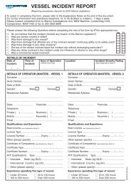
SLSA Certificate <strong>of</strong> Initial Inspection <strong>and</strong> Registration Form<br />
11. DESIGN AND MANUFACTURE OF SURF BOATS<br />
11.1. The use <strong>of</strong> communication devices is NOT permitted by competitors from the<br />
commencement to completion <strong>of</strong> a race.<br />
Note: <strong>Surf</strong> Boat Sweep Coach Mentors, Assessors <strong>and</strong> Level 3 Coaches may, with<br />
the support <strong>of</strong> the appointed Boat Panel, make application to the Referee to utilise<br />
POLICY 5.7 VERSION 4, MAY 2013 17 <strong>of</strong> 23
electronic communication devices at non-championship competitions to further mentor<br />
boat sweeps to gain competency in surf conditions, provided that such mentoring<br />
does not extend to "competing unfairly".<br />
11.2. The use <strong>of</strong> video camera is permitted provided they are installed on a mounting<br />
device <strong>and</strong> toggle strap supplied or recommended by the manufacturer <strong>of</strong> the<br />
device.<br />
11.3. Installation shall be permitted on the splash board (front deck), on the tank opposite<br />
the stroke’s seat (no.4) <strong>and</strong> rear deck.<br />
11.4. The weight <strong>of</strong> any plugs permanently installed into the boat to attach the video<br />
cameras shall be included in the overall “bare weight” <strong>of</strong> the boat.<br />
11.5. The weight <strong>of</strong> other (non-permanently installed) mounts <strong>and</strong> cameras are NOT to be<br />
included in the overall “racing weight” <strong>of</strong> the craft.<br />
11.6. A Boat Sweep (only) is also permitted to have a camera on a helmet (worn)<br />
provided that the camera is installed on a mounting device <strong>and</strong> toggle strap<br />
supplied or recommended by the manufacturer <strong>of</strong> the device<br />
12. FURTHER INFORMATION<br />
11.1. Further information or enquires concerning the construction <strong>of</strong> surf boats should be<br />
directed to:<br />
Physical Address:<br />
Hon National <strong>Surf</strong> Boat Officer, SLSA at<br />
789 Botany Road Rosebery NSW 2018, or,<br />
Postal Address: Locked Bag 1010<br />
Rosebery, NSW 2018<br />
Australia<br />
Photos <strong>and</strong> certificate <strong>of</strong> initial registration<br />
POLICY 5.7 VERSION 4, MAY 2013 18 <strong>of</strong> 23
POLICY 5.7 VERSION 4, MAY 2013 19 <strong>of</strong> 23
POLICY 5.7 VERSION 4, MAY 2013 20 <strong>of</strong> 23
POLICY 5.7 VERSION 4, MAY 2013 21 <strong>of</strong> 23
<strong>Surf</strong> Life Saving Australia Limited<br />
CERTIFICATE OF INITIAL INSPECTION AND REGSTRATION<br />
SURF LIFE SAVING BOAT<br />
DISTRIBUTION WHITE SLSA<br />
BY BUILDER: GREEN PURCHASING CLUB<br />
YELLOW BOAT BUILDER<br />
PINK CLUB’S STATE CENTRE<br />
BLUE INSPECTOR<br />
A. ORDERING INFORMATION:<br />
BOAT ORDERED BY:______________________________________SLSC.STATE:_______________________DATE:_______/______/____<br />
CONSTRUCTION STATUS: REGISTRATION EXPERIENCE STANDARD OTHER DESCRIBE:_____________________ _____<br />
BASIC CONSTRUCTION MATERIALS:_______________________ ____________________________________________________________<br />
_______________________________________________________________________________<br />
*DATE OF SLSA ADVICE TO BUILD:______/______/______<br />
DATE CONSTRUCTION COMMENCED______/_____/______<br />
NOTE:<br />
B. REPORT ON INSPECTION:<br />
MANDATORY FOR REGISTRATION OR EXPERIMENTAL CONSTRUCTION, AS DIRECTED BY SLSA*.<br />
MAY ALSO BE USSED BY SLSA INSPECTION VISITS, OR BY THE BUILDER AS A CHECK LIST RECORD<br />
1. PRELIMINARY INSPECTION ON ADVANCE NOTICE OF BUILDER<br />
INSPECT MOULD CHECK MOULD DIMENSIONS CONSTRUCTION PROCEDURES OTHER DESCRIBE:________________<br />
COMMENT:________________________________________________________________________________________________________<br />
____________________________________________________________________________<br />
SIGNED:_________________________________________SIGNED:___________________________DATE:________/________/_________<br />
BOAT BUILDER<br />
BOAT INSPECTOR<br />
2. INTERMEDIATE INSPECTION DURING CONSTRUCTION AND FITTING OUT<br />
HULL REMOVED FROM MOULD HULL SKIN STRINGERS AND BRACKETS<br />
GUNWALES AND KEEL THWARTS STANCHIONS OTHER LIST:<br />
COMMENT:________________________________________________________________________________________________________<br />
SIGNED:_______________________________________SIGNED:________________________________________DATE:____/____/______<br />
BOAT BUILDER<br />
BOAT INSPECTOR<br />
3. FINAL INSPECTION AT COMPLETION<br />
DECKING BULKHEADS BUOYANCY MATERAIL BUOYANCY TANK INSERT<br />
ROWLOCK FITTING ZERO BALLAST OVERALL FINISH WEIGHING CALIBRATION<br />
THE WEIGHT IN THE BARE STRUCTURAL CONDITION IS _______._______KG (I.A.W CLAUSE 7.)<br />
COMMENT:________________________________________________________________________________________________________<br />
SIGNED:____________________________________SIGNED:___________________________________DATE:________/_______/_______<br />
BOAT BUILDER<br />
BOAT INSPECTOR<br />
C. SLSA BOAT REGISTRATION: (M<strong>and</strong>atory for all <strong>Boats</strong>)<br />
1. CERTIFICATION OF COMPLIANCE<br />
I,______________________________, REGISTERED SLSA SURF BOAT BUILDER, HEREBY DECLARE AND CERTIFY THAT THE ABOVE<br />
MENTIONED SURFBOAT HAS BEEN CONSUTRUCTED IN ACCORDANCE WITH ALL REQUIREMENTS OF THE CURRENT<br />
POLICY 5.7 VERSION 4, MAY 2013 22 <strong>of</strong> 23
SPECIFICATION FOR THE CONSTRUCTION OF SLSA SURF BOATS AND SLSA AGREEMENTS AND INSTRUCTIONS; AND<br />
THAT THE WEIGHT MEASURED IN ACCORDANCE WITH THE SPECIFICATION IS OVER THE MINIMUM ALLLOWABLE, AS IS<br />
RECORDEDIN SECTION B.3 ABOVE.<br />
SIGNED:__________________________________WITNESS:____________________________________DATEl______/________/_________<br />
BOAT BUILDER<br />
ADDRESS:__________________________________________________________________________________________________________<br />
2. BOAT REGISTRATION.<br />
COMPLIANCE LABEL NO.;__________________DATE:______/______/______ STAMPED REGISTRATION NO:____.___/____NO______<br />
EG Stamping for Engraving would be; BT8/01 No 14<br />
Eg Barnet finish August 2001: SLSA Label 00014 08/2001<br />
POLICY 5.7 VERSION 4, MAY 2013 23 <strong>of</strong> 23