4th generation of Coromax pulse generators for ESP's - isesp
4th generation of Coromax pulse generators for ESP's - isesp
4th generation of Coromax pulse generators for ESP's - isesp

You also want an ePaper? Increase the reach of your titles
YUMPU automatically turns print PDFs into web optimized ePapers that Google loves.
4 th <strong>generation</strong> <strong>of</strong> <strong>Coromax</strong> <strong>pulse</strong> <strong>generators</strong> <strong>for</strong><br />
ESP’s<br />
Victor Reyes<br />
FLSmidth Airtech<br />
Denmark<br />
vicr@flsairtech.com<br />
Peter Elholm<br />
FLSmidth Airtech<br />
Denmark<br />
PE@flsairtech.com<br />
1 Abstract:<br />
The first plants using the latest <strong>generation</strong> <strong>of</strong> <strong>Coromax</strong> <strong>pulse</strong> <strong>generators</strong> <strong>for</strong> ESP´s have been<br />
commissioned. The present paper will present the new features developed as well a comparison with<br />
competing types <strong>of</strong> power supplies <strong>for</strong> ESP’s. Among the new features, the use <strong>of</strong> single IGBT’s as<br />
main semiconductor switch and extremely narrow <strong>pulse</strong>s can be mentioned. Furthermore the results<br />
obtained after the commissioning <strong>of</strong> a sinter plant producing 15.000 t/d will be given.<br />
2 Introduction<br />
The tendency in air pollution regulations is a<br />
decrease <strong>of</strong> the accepted levels <strong>for</strong> fine<br />
particles. E.g. the EU has imposed lower limit<br />
on ambient concentration <strong>of</strong> fine particulate<br />
matter (PM2.5). It is well known that <strong>pulse</strong><br />
energization is the most effective means in<br />
charging and filtering fine particulate when<br />
using ESP’s.<br />
In order to improve the state-<strong>of</strong>-the-art in <strong>pulse</strong><br />
energization, Airtech- Air Pollution Control FL-<br />
Smidth has developed the 4 th <strong>generation</strong> <strong>of</strong> its<br />
line <strong>of</strong> <strong>pulse</strong> <strong>generators</strong>. The main goal <strong>for</strong> the<br />
new system was to increase the rate <strong>of</strong> rise <strong>of</strong><br />
the ESP voltage by a factor <strong>of</strong> 2 and in this<br />
way to be able to apply higher voltage levels to<br />
the ESP. This was obtained in practice by<br />
decreasing the <strong>pulse</strong> width correspondingly.<br />
Furthermore, the system is able to apply a<br />
higher <strong>pulse</strong> voltage compared with previous<br />
<strong>generation</strong>s. Other improvements have been<br />
introduced regarding the manner the high<br />
voltage semiconductor switch handles the<br />
sparks occurring inside the ESP.<br />
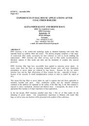
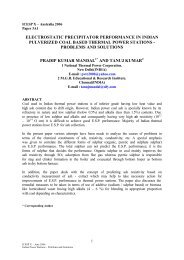
Physically the system comprises one control<br />
cabinet and a HV oil tank, like a traditional TR<br />
set, where the oil tank is placed on the ESP<br />
ro<strong>of</strong>, as shown in Fig. 1.<br />
Fig. 1 <strong>Coromax</strong> HV oil tank<br />
The electrode/collecting system behaves as a<br />
capacitance with losses.The <strong>Coromax</strong> mrk. IV<br />
is designed <strong>for</strong> a rated load <strong>of</strong> 115 nF, but it<br />
can operate with a wide range <strong>of</strong> ESP<br />
capacitances (40% - 200% <strong>of</strong> rated value).<br />
The art <strong>of</strong> <strong>pulse</strong> energization consists <strong>of</strong><br />
narrow HV <strong>pulse</strong>s in the range <strong>of</strong> tenths <strong>of</strong><br />
microseconds, superimposed on a base<br />
voltage, which are applied to an ESP field [1],<br />
[2] generating negative corona.<br />
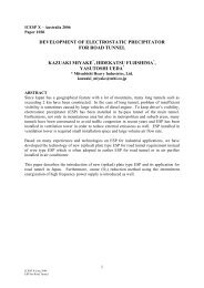
The principle is illustrated in Fig. 2 showing the<br />
<strong>Coromax</strong> voltage wave<strong>for</strong>m compared with the<br />
one generated by a traditional single-phase TR<br />
set (DC-energization). Furthermore, the<br />
smooth DC voltage delivered by a SMPS unit<br />
is shown. Some <strong>of</strong> these units can operate in<br />
the so-called intermittent mode (IE-mode =<br />
intermittent energization) giving a DC voltage<br />
with high ripple and a variety <strong>of</strong> degrees <strong>of</strong><br />
intermittence. But these HV supplies operate in
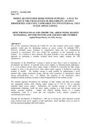
Fig. 3 Simplified main circuit <strong>of</strong> a <strong>Coromax</strong><br />
<strong>pulse</strong> system<br />
Fig. 2 Wave<strong>for</strong>m <strong>of</strong> the output voltage<br />
the millisecond range with modest dv/dt in the<br />
range <strong>of</strong> few kV/ms.<br />
The present version <strong>of</strong> the COROMAX system<br />
dealt with in this paper, aims at improving the<br />
per<strong>for</strong>mance in fine particulate and high<br />
resistivity dust collection by halving the <strong>pulse</strong><br />
width. In this way the dv/dt applied to an ESP<br />
field is doubled (up to 2 kV/µs).<br />
To improve the conditions regarding service<br />
and troubleshooting, other requirements were<br />
to avoid series connection <strong>of</strong> power semiconductors<br />
and placement in insulating oil.<br />
Furthermore, because <strong>of</strong> an eventual higher<br />
sparking level the <strong>pulse</strong> amplitude has been<br />
increased by 10 kV compared with previous<br />
<strong>generation</strong>s.<br />
Be<strong>for</strong>e a <strong>pulse</strong> is generated, the capacitor C S is<br />
charged to a voltage +U PS through the primary<br />
winding <strong>of</strong> the <strong>pulse</strong> trans<strong>for</strong>mer. The coupling<br />
capacitor C C is used <strong>for</strong> avoiding short-circuit<br />
<strong>of</strong> the DC-power supply and it is charged to the<br />
voltage U DC like the ESP capacitance.<br />
Then a series resonant circuit comprising the<br />
storage capacitance C S , the coupling<br />
capacitance C C , the precipitator capacitance<br />
C F and the leakage inductance <strong>of</strong> the <strong>pulse</strong><br />
trans<strong>for</strong>mer (PT) is <strong>for</strong>med. This circuit is<br />
closed when the IGBT switch is turned on.<br />
When this happens an oscillation is initiated<br />
and a current with the wave<strong>for</strong>m shown in Fig.<br />
4 starts flowing through the IGBT. When the<br />
current through the IGBT reaches its zerocrossing<br />
(T/2), it changes direction and<br />
circulates through the reverse diode (D) built in<br />
the IGBT module, until it becomes zero. Then<br />
the period <strong>of</strong> the oscillation (T) is elapsed and<br />
a HV <strong>pulse</strong> has been generated.<br />
In order to fulfil these requirements a solution<br />
with <strong>pulse</strong> trans<strong>for</strong>mer with a suitable trans<strong>for</strong>mation<br />
ratio and a switch made <strong>of</strong> high power<br />
IGBT’s operating at 2.5kV was chosen.<br />
Finally it can be mentioned than considerably<br />
improvements have been introduced in the<br />
automatic control system.<br />
3 Principle <strong>of</strong> operation <strong>of</strong> the<br />
COROMAX system<br />
A simplified diagram <strong>of</strong> the main circuit is<br />
shown in Fig. 3.<br />
The DC base voltage applied to the ESP is<br />
delivered by a controlled HV power supply<br />
(-U DC ). The power <strong>for</strong> <strong>pulse</strong> <strong>generation</strong> is<br />
delivered by another controlled HV supply<br />
(+U PS ).<br />
Fig. 4. Wave<strong>for</strong>ms during a normal high<br />
voltage <strong>pulse</strong>
The voltage across the ESP and the current<br />
through the switch has the wave<strong>for</strong>ms shown<br />
in Fig.4. The voltage rating is 60 kVDC and 80<br />
kV <strong>pulse</strong>, respectively.<br />
The <strong>pulse</strong> current is a sine wave, where the<br />
positive half-cycle corresponds to the IGBT<br />
conduction interval and the negative to the<br />
reverse diode conduction interval. Its rated<br />
value is 9 kA peak . The rated <strong>pulse</strong> width is<br />
75µs. This can be repeated with a frequency,<br />
variable between 2 and 100 pps. The rated<br />
voltage <strong>of</strong> the <strong>pulse</strong> power supply (U PS ) is 2.5<br />
kV.<br />
The <strong>pulse</strong> voltage has a wave<strong>for</strong>m corresponding<br />
to a shifted cosine wave. The equations<br />
describing the wave<strong>for</strong>ms can be found in [1].<br />
The block diagram shown in Fig. 5 illustrates<br />
the complete <strong>pulse</strong> system. In order to cope<br />
with the high <strong>pulse</strong> current level, especially in<br />
case <strong>of</strong> sparks in the ESP, the primary circuit is<br />
divided in two equal branches in parallel.<br />
There<strong>for</strong>e the <strong>pulse</strong> trans<strong>for</strong>mer comprises 2<br />
primary windings, improving the current distribution<br />
between the 2 IGBT’s. The DC voltage<br />
supply (U DC ) and the <strong>pulse</strong> supply (U PS ) are fed<br />
from the three-phase AC line.<br />
This voltage level is raised by HV trans<strong>for</strong>mers<br />
The output <strong>of</strong> the <strong>pulse</strong> power supply is filtered<br />
by L ps1 , L ps2 , C s1 and C s2 .<br />
The <strong>pulse</strong> <strong>for</strong>ming network is the same as the<br />
one shown in Fig. 3 with the exception that, in<br />
practice, there are 2 parallel branches in the<br />
primary circuit. Furthermore, in parallel with<br />
each IGBT is connected a clamping network,<br />
consisting <strong>of</strong> a diode D cl in series with a large<br />
capacitor C cl , which function will be discussed<br />
later.<br />
4 Automatic control unit<br />
The firing angle <strong>for</strong> both power supplies is<br />
determined by the control unit BCU PC. This is<br />
placed in the control cabinet and<br />
communicates with control unit BCU LVJB at<br />
the HV tank via a CAN Bus. These units<br />
include the control strategies, spark<br />
classification, monitoring and alarm processing<br />
system. The operation <strong>of</strong> the system is<br />
per<strong>for</strong>med from the EPCU (EsP Control Unit),<br />
which also takes care <strong>of</strong> the rapping control<br />
and heating <strong>of</strong> insulators and hoppers. EPCU<br />
is common <strong>for</strong> a number <strong>of</strong> ESP bus-sections<br />
but typically <strong>for</strong> one ESP chamber.<br />
The control panel <strong>of</strong> the EPCU is shown in<br />
Fig.6.<br />
Fig. 5 Block diagram <strong>of</strong> the COROMAX<br />
and rectified by three-phase bridge rectifiers.<br />
The output voltages (U DC ,U PS ) are controlled<br />
by three-phase thyristor controllers by varying<br />
the primary voltage <strong>of</strong> the HV trans<strong>for</strong>mer.<br />
Each controller receives the firing <strong>pulse</strong>s from<br />
a firing PC board.<br />
The output <strong>of</strong> the DC power supply is passed<br />
through a LC filter with capacitive input, whose<br />
main function is to keep the base voltage<br />
smooth, especially after firing a HV <strong>pulse</strong>.<br />
Fig. 6 Front panel <strong>of</strong> the control system<br />
When treating medium and high resistivity<br />
dusts, an accurate control <strong>of</strong> the base voltage<br />
is quite important. The EPCU controls its level<br />
in a way that the generated ‘DC corona<br />
current’ can be kept at a setpoint <strong>of</strong> normally a<br />
‘few milliamps’. In this way back corona can be<br />
avoided.
This ‘DC corona current’ is the current flowing<br />
between two consecutive <strong>pulse</strong>s after the ion<br />
cloud generated by the first one has reached<br />
the collecting plates. This means that this<br />
current has to be measured sampling the<br />
corresponding signals just be<strong>for</strong>e the next<br />
<strong>pulse</strong> is generated. Because a typical<br />
repetition frequency in case <strong>of</strong> medium dust<br />
resistivity is 50 - 60 pps, the control system<br />
has a time interval <strong>of</strong> 17 - 20 ms to per<strong>for</strong>m the<br />
measurement. This measurement was not<br />
possible in previous <strong>generation</strong>s and may be<br />
considered as a major improvement in the new<br />
<strong>Coromax</strong>.<br />
clamping diode is biased in the <strong>for</strong>ward<br />
direction and the current surge <strong>pulse</strong> charges<br />
the clamping capacitor. If this is sufficient<br />
large, the voltage increase in C Cl is limited and<br />
the overvoltage across the IGBT’s can be kept<br />
at few hundred volts.<br />
A typical example is seen if Fig. 6, showing<br />
what happens in case <strong>of</strong> a <strong>pulse</strong> spark.<br />
5 IGBT switch function<br />
The HV switch is the heart <strong>of</strong> a <strong>pulse</strong> system<br />
and the most critical situation <strong>for</strong> the<br />
semiconductors used, is the occurrence <strong>of</strong><br />
sparks.<br />
Normally the sparks occurs around the top <strong>of</strong><br />
the <strong>pulse</strong>, but they can also occur earlier or<br />
later, depending on the mechanical condition<br />
<strong>of</strong> the ESP and/or the resistivity <strong>of</strong> the<br />
particulate removed by the ESP. These sparks<br />
are named <strong>pulse</strong> sparks.<br />
(a)<br />
Occasionally sparks may occur shortly after a<br />
<strong>pulse</strong> and they are named DC-sparks, as only<br />
the base voltage is applied to the ESP at the<br />
spark instant.<br />
The previous <strong>pulse</strong> systems used HF thyristors<br />
connected in series as a switch [1,2]. In case<br />
<strong>of</strong> sparks the switch is exposed to a<br />
considerable overvoltage. To cope with this<br />
situation the switch can be oversized using a<br />
larger number <strong>of</strong> elements in series, which is<br />
too expensive. The normal solution used is<br />
<strong>generation</strong> <strong>of</strong> protection firing <strong>pulse</strong>s. Because<br />
<strong>of</strong> the connection <strong>of</strong> many thyristors in series,<br />
this kind <strong>of</strong> protection is critical, as explained in<br />
[2].<br />
By using an IGBT switch instead, this can be<br />
turned <strong>of</strong>f when a spark is detected. This gives<br />
a much more simple protection principle <strong>for</strong> the<br />
IGBT switch. When the IGBT’s are turned <strong>of</strong>f it<br />
is necessary to have an alternative path <strong>for</strong> the<br />
energy stored in the system. This function is<br />
per<strong>for</strong>med by the clamping diode D cl and the<br />
clamping capacitor C cl . When the IGBT’s are<br />
turned <strong>of</strong>f after detection <strong>of</strong> a <strong>pulse</strong> spark, the<br />
(b)<br />
Fig. 7 Wave<strong>for</strong>ms in case <strong>of</strong> <strong>pulse</strong> spark.<br />
These wave<strong>for</strong>ms are obtained with the<br />
simulation program POWERSIM and<br />
correspond to rated values. Fig. 7.a shows a<br />
<strong>pulse</strong> spark occurring on top <strong>of</strong> the <strong>pulse</strong> just<br />
after the zero-crossing <strong>of</strong> the IGBT current<br />
(Iigbt). As seen the ESP voltage (Uesp) drops<br />
very fast from 140 kV to 0. The IGBT current
changes direction and begins to increase, but<br />
after a delay <strong>of</strong> few microseconds the IGBT’s<br />
are turned <strong>of</strong>f and the <strong>pulse</strong> current<br />
commutates to the clamping network. The<br />
current through the clamping capacitor (ICcl) is<br />
shown in Fig.7.b.<br />
Here it is seen that C cl is charged by this<br />
current and the overvoltage applied to the<br />
IGBT’s is limited to about 200 V. Fig. 7 shows<br />
the currents in one parallel branch only. During<br />
a normal <strong>pulse</strong> the peak current through one<br />
IGBT is 4.2 kA. Fig. 7 also shows that the<br />
IGBT’s are not exposed to current surges,<br />
because these are overtaken by the clamping<br />
network made <strong>of</strong> passive components.<br />
In case <strong>of</strong> DC-sparks the IGBT’s are already<br />
turned <strong>of</strong>f, so the only possible current path <strong>for</strong><br />
the surge is the clamping network.<br />
This solution has been patented in a number <strong>of</strong><br />
countries, the EU and EEUU among them.<br />
The IGBT’s are fired by a commercially<br />
existing IGBT driver, They are physically<br />
placed in a LV junction box (LVJB) attached to<br />
the oil tank as seen in Fig. 8.<br />
Fig. 9 1200A/3300 V IGBT used as switch<br />
As shown, the switch is implemented with<br />
commercially available elements and no series<br />
connection is used. The switch is mounted in<br />
air, so measurements and eventual troubleshooting<br />
and replacement is much easier.<br />
6 Practical experiences<br />
After a long test <strong>of</strong> the prototype in a Danish<br />
power plant a number <strong>of</strong> units have been sold.<br />
At the moment more than 20 units are in<br />
operation, mainly in sinter strand plants and<br />
also in a power plant.<br />
6.1 Electrical operation<br />
The main wave<strong>for</strong>ms are easy to collect via<br />
existing BNC connectors. The wave<strong>for</strong>ms<br />
corresponding to a normal <strong>pulse</strong> are shown in<br />
Fig. 10.<br />
Fig. 8 IGBTs mounted in LVJB<br />
The IGBT’s are mounted on a heat sink with<br />
cooling fins, which is in contact with the oil<br />
inside the HV tank. Fig. 9 shows one <strong>of</strong> the<br />
utilized IGBT’s together with the corresponding<br />
IGBT driver.<br />
Fig. 10 ESP and IGBT voltage and IGBT<br />
current during a normal <strong>pulse</strong>.<br />
The voltage across the IGBT is 2.5 kV (rated<br />
value) causing a peak current <strong>of</strong> about 4.8 kA<br />
flowing through the switch and a total ESP<br />
voltage <strong>of</strong> 132 kV (U DC = 55 kV). The <strong>pulse</strong><br />
width is 78 µs.
Fig. 11 illustrates a <strong>pulse</strong> spark occurring after<br />
the top <strong>of</strong> the <strong>pulse</strong>, showing the ESP voltage<br />
and the current through one IGBT. It is seen<br />
that the current through the IGBT is only<br />
flowing during the normal <strong>pulse</strong>, but when the<br />
sparks occurs the IGBT is turned <strong>of</strong>f. The<br />
surge current is then overtaken by the<br />
clamping network, as illustrated in Fig. 7.<br />
African coal, producing a medium resistivity<br />
flyash.<br />
The ESP is from FLS comprising two<br />
chambers, with 4 bus-sections each, energized<br />
with 8 third <strong>generation</strong> <strong>Coromax</strong> systems.<br />
Each <strong>Coromax</strong> energizes 4320 m 2 (400 mm<br />
wide spacing) <strong>of</strong> collecting area, corresponding<br />
to a capacitive load <strong>of</strong> 120 nF. The rated mean<br />
current is 600 mA.<br />
The gas flow is 32.000m 3 /min and the dust<br />
load is 18.5 gr/Nm 3 dry @ 6% O 2 .<br />
Fig. 11 ESP voltage and IGBT current<br />
during a <strong>pulse</strong> spark.<br />
The new <strong>Coromax</strong> energizes the 2 nd bussection<br />
<strong>of</strong> the West chamber. A switch box was<br />
mounted allowing and easy change-over with<br />
the existing <strong>pulse</strong> system. The electrical<br />
operation is best illustrated by the CVC shown<br />
in Fig. 13.<br />
During normal (repetitive) operation the wave<strong>for</strong>m<br />
<strong>of</strong> the ESP voltage is shown in Fig. 12.<br />
Fig. 13 Pulse and DC I-V characteristics<br />
Fig. 12 ESP voltage and IGBT voltage at<br />
normal repetitive operation.<br />
Fig. 12 shows also the occurrence <strong>of</strong> a spark<br />
and the following voltage recovery. It is also<br />
seen the amplitude <strong>of</strong> the <strong>pulse</strong>s follow the<br />
envelope <strong>of</strong> the IGBT voltage very close.<br />
6.2 Site experiences<br />
6.2.1 Plant No. 1<br />
The first system (prototype) was installed in a<br />
Danish power plant, the unit #3 at Nordjyllandsværket.<br />
Unit #3 has a nominal load <strong>of</strong><br />
350 MW and the boiler is fired with different<br />
coal blends. The load varies typically between<br />
80 and 100% according to the daily demands.<br />
The typical coal blend during the test period<br />
were a mix <strong>of</strong> Russian, Indonesian and South<br />
African or Russian, Colombian and South<br />
As shown, total voltages (DC+<strong>pulse</strong>) <strong>of</strong> 113 kV<br />
are possible (U DC = 50 kV). The increase in the<br />
<strong>pulse</strong> voltage compared with the old <strong>Coromax</strong><br />
is 4-6 kV, but because the prototype only<br />
energizes 1/8 <strong>of</strong> the ESP, no appreciable<br />
emission reduction was observed. The<br />
emission level is below 50 mg/Nm 3 , typically<br />
35 mg/Nm 3 .<br />
Moreover, Fig. 13 clearly indicates the<br />
outstanding feature <strong>of</strong> <strong>pulse</strong> energization,<br />
where the ESP current can be varied independently<br />
<strong>of</strong> the voltage, just by varying the <strong>pulse</strong><br />
repetition frequency.
6.2.2 Plant No. 2<br />
The first commercial units where<br />
commissioned in 2010 at the waste gas ESP at<br />
sinter plant in South America.<br />
The sinter waste gas is characterized by fine<br />
particulate high resistivity dust and the<br />
<strong>Coromax</strong> with its individual control <strong>of</strong> voltage<br />
and current is in particular appropriate <strong>for</strong> that<br />
process.<br />
A new ESP was delivered comprising two<br />
chambers with 3 sections each. Both inlet<br />
sections are energized with single phase TR´s<br />
and the other 4 sections with 4 th <strong>generation</strong><br />
<strong>Coromax</strong> systems. See Fig. 1.<br />
The plant has sinter strand <strong>of</strong> 450 m 2 designed<br />
<strong>for</strong> a production <strong>of</strong> 15000 t/day. The ESP is<br />
designed <strong>for</strong> a gas flow <strong>of</strong> 38.868 m 3 /min and<br />
an inlet temperature <strong>of</strong> 160˚C. The guaranteed<br />
dust emission is 50 mg/Nm 3 (dry).<br />
The capacitive load <strong>for</strong> each <strong>Coromax</strong> system<br />
is about 145 nF, i.e. 25 % higher than rated<br />
load. The rated <strong>pulse</strong> voltage is 80 kV, the<br />
rated base voltage is 60 kV and the rated<br />
mean ESP current is 600 mA.<br />
The per<strong>for</strong>mance test was made with a<br />
production <strong>of</strong> 15800 t/day, a gas flow rate <strong>of</strong><br />
29245 m 3 /min and a temperature about 165°C.<br />
The result was 5 mg/Nm 3 that was much below<br />
the guarantee limit. Some <strong>of</strong> the lower value<br />
may relate to the lower gas flow rate. However,<br />
the main part may relate to the unique feature<br />
<strong>of</strong> the new <strong>Coromax</strong>.<br />
6.2.3 Plant No. 3<br />
The second commercial units were also<br />
installed in a sinter plant waste gas ESP in<br />
South America and were commissioned late in<br />
2010. An existing 2 chambers ESP, each with<br />
3 sections, were furnished with new internals<br />
and 6 <strong>Coromax</strong> systems.<br />
The plant has a sinter strand <strong>of</strong> 146 m 2<br />
designed <strong>for</strong> a production <strong>of</strong> 6100 t/day. The<br />
ESP is designed <strong>for</strong> a gas flow <strong>of</strong> 18.350<br />
m 3 /min and an inlet temperature <strong>of</strong> 110˚C. The<br />
guaranteed dust emission is 30 mg/Nm 3 (dry).<br />
rated base voltage is 60 kV and the rated<br />
mean ESP current is 600 mA.<br />
The per<strong>for</strong>mance test was made with a<br />
production <strong>of</strong> 5425 t/day, a gas flow rate <strong>of</strong><br />
19.088 m 3 /min and an inlet temperature about<br />
90°C. The result was 6 mg/Nm 3 , that is in a<br />
very safe distance to the guaranteed limit. With<br />
operational data close to the design, the much<br />
better results relate solely to the <strong>Coromax</strong><br />
features.<br />
7 Conclusions<br />
It has been possible to include improvements<br />
with respect to previous <strong>Coromax</strong> <strong>generation</strong>s.<br />
Among them, the following can be mentioned:<br />
● Almost twice higher dv/dt applied to the ESP<br />
as the <strong>pulse</strong> width is now only 75 µs.<br />
● 10 kV higher <strong>pulse</strong> voltage allowing a better<br />
particle charging.<br />
● Modern up-to-date HV switch with commercially<br />
available IGBT’s mounted in air. No<br />
series connected modules are needed, making<br />
possible an easy maintenance and<br />
troubleshooting.<br />
● More simple and efficient way <strong>of</strong> coping with<br />
sparks, due to the turn-<strong>of</strong>f capabilities <strong>of</strong><br />
IGBT’s.<br />
● Up-to-date automatic control system, including<br />
control <strong>of</strong> rappers and heaters.<br />
Regarding emission guarantees, these have<br />
been achieved without problems. Further, the<br />
results have been beyond expectation.<br />
8 Litterature<br />
[1] K. Parker. ‘Electrical operation <strong>of</strong> electrostatic<br />
precipitators’. IEE Power and Energy<br />
Series. 2003.<br />
[2] V. Reyes ‘Semiconductor switch <strong>for</strong> HV<br />
<strong>pulse</strong> <strong>generation</strong>’. 20 th Conference on Power<br />
Conversion, Munich, 1990. Germany.<br />
The capacitive load <strong>of</strong> each <strong>Coromax</strong> is about<br />
90 nF. The rated <strong>pulse</strong> voltage is 80 kV, the