io 3d pico up/flat/plug/track(PDF/5.7 MB) - Occhio
io 3d pico up/flat/plug/track(PDF/5.7 MB) - Occhio
io 3d pico up/flat/plug/track(PDF/5.7 MB) - Occhio

You also want an ePaper? Increase the reach of your titles
YUMPU automatically turns print PDFs into web optimized ePapers that Google loves.
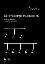
<strong>io</strong> <strong>3d</strong> <strong>pico</strong><br />
Montageanleitung<br />
mounting instruct<strong>io</strong>ns<br />
<strong>up</strong><br />
<strong>flat</strong><br />
<strong>plug</strong><br />
<strong>track</strong>
<strong>io</strong> <strong>3d</strong> <strong>pico</strong><br />
Montageanleitung S. 2<br />
mounting instruct<strong>io</strong>ns p. 67<br />
<strong>up</strong><br />
<strong>flat</strong><br />
<strong>plug</strong><br />
<strong>track</strong>
Inhalt<br />
Sicherheitshinweise 4<br />
Produktbeschreibung 5<br />
1 Voreinstellung head 7<br />
2 Montage head 11<br />
3 Montage body 19<br />
4 Montage head + body 55<br />
5 touchless Dimmfunkt<strong>io</strong>n 61<br />
Informat<strong>io</strong>nen 64<br />
Technische Daten 65<br />
3
Sicherheitshinweise<br />
Lesen Sie die Montage-/Gebrauchsanweisung<br />
sorgfältig durch, bevor<br />
Sie die Leuchte installieren. Beachten<br />
Sie die Sicherheitshinweise in<br />
dieser Anleitung genau und Bewahren<br />
Sie die Anleitung auf.<br />
Erklärung der Kennzeichnung<br />
Dieses Zeichen macht Sie auf eine<br />
gefährliche Situat<strong>io</strong>n aufmerksam,<br />
die eine schwere Verletzung oder<br />
den Tod nach sich ziehen kann,<br />
wenn sie nicht beachtet wird. Es<br />
macht Sie zudem auf mögliche<br />
Sachschäden und andere wichtige<br />
Informat<strong>io</strong>nen in Verbindung mit<br />
diesem Produkt aufmerksam.<br />
Allgemeine Sicherheitshinweise<br />
Die Montage von Elektrokomponenten<br />
darf nur von qualifiziertem<br />
Fachpersonal durchgeführt werden.<br />
Reparaturarbeiten dürfen nur<br />
von autorisiertem Fachpersonal<br />
oder dem Hersteller durchgeführt<br />
werden.<br />
Vor allen Arbeiten am Strahler<br />
(Installat<strong>io</strong>n, Leuchtmittelwechsel,<br />
Reinigung etc.) diesen unbedingt<br />
vom Stromnetz trennen.<br />
0.2m<br />
Sicherheitsabstand zu brennbaren<br />
Objekten einhalten: 20 cm!<br />
Dieses Zeichen macht Sie auf heiße<br />
Oberflächen aufmerksam, deren<br />
Berührung Verbrennungen zur Folge<br />
haben können.<br />
Dieses Zeichen macht Sie auf Situat<strong>io</strong>nen<br />
aufmerksam, bei denen Sie<br />
direkt in das Licht der LED blicken<br />
könnten. Dies kann zu Nachbildern<br />
und bei längerer Dauer zu Schädigungen<br />
der Augen führen.<br />
Achtung: Die Oberfläche des Strahlers<br />
kann nach längerer Betriebsdauer<br />
heiß sein!<br />
Vor allen Arbeiten am Strahler<br />
(Montage des Strahlers, Wechsel<br />
des Leuchtmittels, Wechsel der<br />
Inserts, usf.), Strahler immer ausschalten<br />
und mindestens 30 Minuten<br />
abkühlen lassen.<br />
4
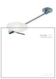
Produktbeschreibung<br />
LED Decken- / Wandstrahler mit kugelförmigem<br />
Kopf und Linsenoptik. Frei<br />
beweglich durch Occh<strong>io</strong> <strong>3d</strong>-Kinematik<br />
mit zwei im Winkel von 45° zueinander<br />
stehenden Drehachsen, Bedienung über<br />
wärmeentkoppelte Grip-pads. Kopf<br />
für Wartungszwecke abnehmbar, LED<br />
wechselbar.<br />
<strong>io</strong> <strong>3d</strong> <strong>pico</strong> steht in den Montagevarianten<br />
„<strong>up</strong>“ (Aufbau/feste Decken), „<strong>flat</strong>“<br />
(Hohldecke/Deckendose), „<strong>plug</strong>“ (Hohldecke<br />
mit Einputzplatte) und „<strong>track</strong>“<br />
(1- oder 3- Phasen Stromschiene) zur<br />
Verfügung.<br />
Leistung 18W oder 13W (vorwählbar),<br />
dimmbar bauseits über dimmbares<br />
Vorschaltgerät oder per Gestensteuerung<br />
über touchless Dimmfunkt<strong>io</strong>n<br />
(deaktivierbar).<br />
Lichtwirkung über opt<strong>io</strong>nale inserts<br />
veränderbar, dichroitische Farbfilter<br />
zusätzlich einsetzbar.<br />
Oberflächenkombinat<strong>io</strong>nen von Kopf,<br />
Pads, Arm und Fuß frei konfigurierbar,<br />
Pads wechselbar.<br />
5
1<br />
Voreinstellung<br />
head<br />
7
Wahl Betriebsmodus<br />
Der head verfügt über einen Drehschalter,<br />
mit dem die Lichtleistung (Watt)<br />
und die touchless Dimmfunkt<strong>io</strong>n für<br />
das berührungslose Dimmen/Schalten<br />
eingestellt werden kann.<br />
Im Auslieferungszustand ist der Drehschalter<br />
auf „18W“ eingestellt.<br />
Die jeweiligen Einstellmöglichkeiten werden<br />
in nebenstehender Tabelle erläutert.<br />
Wir empfehlen für diesen Strahler<br />
die Einstellungen „18W“ (Dimmung<br />
über bauseitigen Dimmer) oder<br />
„18W SENSOR“ (Dimmung über<br />
integrierten berührungslosen Sensordimmer).<br />
Drehschalter mit der Fingerk<strong>up</strong>pe auf<br />
die gewünschte Leistung und Funkt<strong>io</strong>n<br />
einstellen.<br />
Achtung: Die Oberfläche des Strahlers<br />
wird im 18W Dauertbetrieb sehr<br />
warm!<br />
Nicht direkt in die Lichtquelle<br />
blicken!<br />
Vor dem Einstellen des Drehschalters<br />
(z.B. nachträgliche Einstellung)<br />
head immer vom body abnehmen.<br />
8
Voreinstellung head<br />
1<br />
Schalterstellung Funkt<strong>io</strong>n Empfohlene Einstellung für<br />
18W<br />
18W SENSOR<br />
13W<br />
13W SENSOR<br />
Lichtleistung: 18W · Wand- und Deckenleuchten<br />
touchless Dimmfunkt<strong>io</strong>n: außerhalb des Handbereichs<br />
AUS<br />
· An-/Ausschalten über Netzschalter<br />
· Dimmung über bauseitigen Dimmer<br />
Lichtleistung: 18W · Wand- und Deckenleuchten außerhalb<br />
des Handbereichs und falls<br />
touchless Dimmfunkt<strong>io</strong>n:<br />
EIN<br />
höhere Lichtleistungen gewünscht<br />
sind. Achtung: Strahler wird im<br />
18W Dauertbetrieb sehr warm!<br />
· An-/Ausschalten und Dimmung<br />
über touchless Dimmfunkt<strong>io</strong>n<br />
(Handbewegung)*<br />
· Zuverlässiger Sensorbetrieb ist<br />
nur dann sichergestellt wenn der<br />
Schutzleiter korrekt angeschlossen<br />
ist.<br />
Lichtleistung: 13W · Leuchten innerhalb des Handbereichs,<br />
insbesondere Tisch-/<br />
touchless Dimmfunkt<strong>io</strong>n:<br />
AUS<br />
Leseleuchten und Bodenstrahler<br />
· An-/Ausschalten über Netzschalter<br />
· Dimmung über bauseitigen Dimmer<br />
Lichtleistung: 13W<br />
touchless Dimmfunkt<strong>io</strong>n:<br />
EIN<br />
· Leuchten innerhalb des Handbereichs,<br />
insbesondere Tisch-/<br />
Leseleuchten und Bodenstrahler<br />
· An-/Ausschalten und Dimmung<br />
über touchless Dimmfunkt<strong>io</strong>n<br />
(Handbewegung)*<br />
· Zuverlässiger Sensorbetrieb ist<br />
nur dann sichergestellt wenn der<br />
Schutzleiter korrekt angeschlossen<br />
ist.<br />
*touchless Dimmfunkt<strong>io</strong>n: Anleitung s. Seite 62<br />
9
2<br />
Montage head<br />
11
Montage head<br />
2<br />
Aufbau <strong>io</strong> head<br />
head<br />
(LED bereits montiert)<br />
pads<br />
Inserts<br />
(opt<strong>io</strong>nal)<br />
Farbfilter<br />
satiniertes<br />
Glas<br />
softedge<br />
Glas<br />
Fresnel<br />
Linse<br />
Linse<br />
13
Pads einsetzen<br />
Pads in die seitlichen Mulden des head<br />
einlegen …<br />
… und so weit drehen, bis sie einrasten<br />
und magnetisch gehalten werden.<br />
Click!<br />
Oberfläche der LED (gelbe Fläche)<br />
nicht berühren! Die LED kann dadurch<br />
beschädigt werden.<br />
Um Kratzer zu vermeiden, Einzelteile<br />
des Strahlers bei der Montage<br />
immer auf eine weiche Unterlage<br />
legen!<br />
14
Montage head 2<br />
Pads entnehmen:<br />
Pad am unteren Rand (Linsen-Seite)<br />
nach innen drücken, ...<br />
… dass es sich auf der gegenüberliegenden<br />
Seite abhebt und entnehmen<br />
lässt.<br />
Pad entnehmen.<br />
15
Inserts einsetzen (opt<strong>io</strong>nal)<br />
head<br />
Inserts<br />
(opt<strong>io</strong>nal)<br />
Farbfilter<br />
(rot, grün, blau, gelb, magenta)<br />
satiniertes Glas<br />
(für weiche<br />
Lichtverteilung)<br />
softedge Glas<br />
(Für weiche<br />
Lichtkontur)<br />
Fresnel Linse<br />
(zur Bündelung<br />
des Lichts)<br />
Linse<br />
(für Blendfreies,<br />
gerichtetes Licht)<br />
16
Montage head 2<br />
Linse mit der Rückseite nach oben auf<br />
eine weiche Unterlage legen.<br />
Inserts bis zum Anschlag in die<br />
Halterungen einschieben.<br />
Click!<br />
In die Halteclips der Linse können max.<br />
zwei Inserts eingesetzt werden.<br />
Posit<strong>io</strong>n der Fresnel Linse:<br />
Farbfilter<br />
(opt<strong>io</strong>nal)<br />
Fresnel Linse so einsetzen, dass die<br />
gerillte Seite zur Linse zeigt.<br />
Fresnel Linse<br />
Linse<br />
17
Linse einsetzen 2<br />
Linse in die Öffnung des head einsetzen<br />
und …<br />
Click!<br />
… so weit drehen, bis die Linse von den<br />
radial angeordneten Magneten gehalten<br />
wird.<br />
Entnehmen:<br />
Linse so weit drehen bis sich die<br />
Magnetkraft löst und herausnehmen.<br />
Der head ist nun für die Montage head<br />
+ body vorbereitet.<br />
Oberfläche der LED (gelbe Fläche)<br />
nicht berühren! Die LED kann dadurch<br />
beschädigt werden.<br />
18
3<br />
Montage body<br />
<strong>io</strong> <strong>3d</strong> <strong>pico</strong> <strong>up</strong><br />
für feste Decke<br />
21<br />
<strong>io</strong> <strong>3d</strong> <strong>pico</strong> <strong>flat</strong><br />
für Hohlraum-/Einputzdose<br />
27<br />
<strong>io</strong> <strong>3d</strong> <strong>pico</strong> <strong>plug</strong><br />
für Hohldecke mit Einputzplatte<br />
für Hohldecke mit Panel<br />
33<br />
41<br />
<strong>io</strong> <strong>3d</strong> <strong>pico</strong> <strong>track</strong><br />
für 1- oder 3-Phasenschiene<br />
51<br />
19
<strong>io</strong> <strong>3d</strong> <strong>pico</strong> <strong>up</strong><br />
3<br />
Installat<strong>io</strong>n auf<br />
festem Untergrund<br />
230V AC<br />
Netzanschlussleitung<br />
Montageplatte hoch<br />
Schrauben<br />
(Hohlraumdose)<br />
Occh<strong>io</strong> Konverter<br />
48V, 25W<br />
Leuchtenkabel mit<br />
Stecker<br />
Leuchtenkörper<br />
Inbusschrauben<br />
Cover hoch<br />
21
Installat<strong>io</strong>n<br />
Enden des Netzkabels auf 5 cm ablängen<br />
und an den Enden abisolieren.<br />
230V AC<br />
Netzanschlussleitung<br />
5 cm<br />
Montageplatte über den Stromauslass<br />
an Wand/Decke setzen und so drehen,<br />
dass die Langlöcher die gewünschte<br />
Ausrichtung haben. Posit<strong>io</strong>nen der<br />
Bohrlöcher anzeichnen.<br />
Auf den Verlauf von Stromleitungen<br />
achten!<br />
Zwei Löcher ø 6 mm bohren, Dübel<br />
bündig einsetzen und Montageplatte<br />
anschrauben (Schrauben und Dübel<br />
sind im Lieferumfang enthalten).<br />
Darauf achten, dass die Schrauben<br />
bündig mit der Montageplatte abschließen.<br />
22
<strong>io</strong> <strong>3d</strong> <strong>pico</strong> <strong>up</strong><br />
3<br />
Klappe in der Mitte des Konverters mit<br />
Hilfe eines Schraubendrehers öffnen.<br />
Konverter bündig in die Montageplatte<br />
einrasten.<br />
Dabei die Enden der Netzleitung durch<br />
die Öffnung des Konverters führen.<br />
Click!<br />
Anschluss einzeln<br />
L L<br />
N N<br />
Kabelenden der Netzleitung nach<br />
Schema mithilfe einer Spitzzange an die<br />
Klemmen des Konverters anschließen.<br />
230V<br />
Für die Sensorfunkt<strong>io</strong>n ist der<br />
Erdungsanschluss dringend erforderlich!<br />
Anschluss mit Durchverdrahtung<br />
L L<br />
N N<br />
230V<br />
weitere<br />
Leuchte<br />
$Achtung!<br />
Vor der Montage alle stromführenden<br />
Leitungen vom Stromnetz trennen!<br />
23
Installat<strong>io</strong>n<br />
Klappe des Konverters schließen.<br />
Click!<br />
Stecker des Leuchtenkörpers in die<br />
Buchse des LED-Konverters stecken.<br />
Schutzschlauch des Leuchtenarms<br />
nicht entfernen.<br />
Click!<br />
24
<strong>io</strong> <strong>3d</strong> <strong>pico</strong> <strong>up</strong><br />
3<br />
Kabel in die Aussparung des Konverters<br />
legen – nicht einklemmen!<br />
Leuchtenkörper mit mitgelieferten<br />
Schrauben (Inbus) auf beide Abstandshalter<br />
der Montageplatte schrauben.<br />
Dabei darauf achten, dass die Rastnasen<br />
des Leuchtenkörpers (siehe<br />
Detail) bündig auf den Abstandshaltern<br />
aufliegen.<br />
Schutzfolie vom Cover abnehmen.<br />
Click!<br />
Cover vorsichtig über den Leuchtenarm<br />
führen.<br />
Durch Rechtsdrehung arretieren.<br />
Schutzschlauch vom Leuchtenarm<br />
entfernen.<br />
Der body ist nun fertig montiert<br />
25
<strong>io</strong> <strong>3d</strong> <strong>pico</strong> <strong>flat</strong> 3<br />
Externer<br />
Konverter*<br />
230V AC<br />
Netzanschlussleitung<br />
Hohlraumdose<br />
(bauseitig)<br />
Montageplatte flach<br />
Sekundärseitiges Kabel<br />
des externen Occh<strong>io</strong> Konverters<br />
(mit grüner Buchse)<br />
oder im Lieferumfang<br />
beigelegtes Kabel zum<br />
Anschluß an Gleichspannungsquelle<br />
von Fremdanbietern<br />
(mit grüner Buchse)<br />
Schrauben<br />
(Hohlraumdose)<br />
Leuchtenkabel mit<br />
Stecker<br />
Leuchtenkörper<br />
Inbusschrauben<br />
Cover flach<br />
* externer<br />
LED Konverter<br />
(Gleichspannungsquelle)<br />
42 … 48V DC,<br />
min. 22 W pro<br />
Strahler<br />
27
Installat<strong>io</strong>n<br />
Externer<br />
Occh<strong>io</strong><br />
Konverter<br />
230V AC<br />
Netzanschlussleitung<br />
Externen Occh<strong>io</strong> Konverter<br />
anschließen (siehe Beiblatt zum<br />
Konverter):<br />
Konverter nach Schema an die Netzleitung<br />
anschließen.<br />
LED-Anschlusskabel im Konverter<br />
einstecken.<br />
Buchse des LED-Anschlusskabels<br />
durch die Hohlraum-/Einputzdose nach<br />
außen führen.<br />
LED Anschlusskabel vom Konverter<br />
oder LED Verlängerungs kabel mit<br />
Buchse<br />
Konverter<br />
(Fremdhersteller)<br />
230V AC<br />
Netzanschlussleitung<br />
Konverter eines Fremdherstellers<br />
anschließen (siehe Beiblatt zum<br />
Konverter):<br />
Konverter nach Schema an die Netzleitung<br />
anschließen.<br />
Kabel mit LED-Buchse an den Konverter<br />
anschließen.<br />
Technische Hinweise des jeweiligen<br />
Herstellers beachten!<br />
Schwarz = Pluspol, Weiß = Minuspol<br />
Buchse des LED Verlängerungskabels<br />
durch die Hohlraum-/Einputzdose nach<br />
außen führen.<br />
28<br />
LED Verlängerungs kabel mit<br />
Buchse vom Konverter<br />
$Achtung!<br />
Vor der Montage alle stromführenden<br />
Leitungen vom Stromnetz trennen!
<strong>io</strong> <strong>3d</strong> <strong>pico</strong> <strong>flat</strong> 3<br />
Montageplatte an die Hohlraumdose<br />
schrauben. Dabei die Buchse des<br />
LED-Anschlusskabels durch die Öffnung<br />
führen.<br />
Darauf achten, dass die Schrauben<br />
bündig mit der Montageplatte abschließen.<br />
Stecker des Leuchtenkörpers mit der<br />
Buchse des LED-Anschlusskabels<br />
verbinden.<br />
Schutzschlauch des Leuchtenarms<br />
nicht entfernen.<br />
29
Installat<strong>io</strong>n 3<br />
Kabel mit Steckverbindung in den Hohlraum<br />
zurückführen.<br />
Leuchtenkörper mit mitgelieferten<br />
Schrauben (Inbus) auf die Montageplatte<br />
schrauben.<br />
Schutzfolie vom Cover abnehmen.<br />
Click!<br />
Cover vorsichtig über den Leuchtenarm<br />
führen.<br />
Durch Rechtsdrehung arretieren.<br />
Schutzschlauch vom Leuchtenarm<br />
entfernen.<br />
Der body ist nun fertig montiert.<br />
30
<strong>io</strong> <strong>3d</strong> <strong>pico</strong> <strong>plug</strong> (Einputzplatte)<br />
3<br />
Montage mit Einputzplatte<br />
Sekundärseitiges Kabel des<br />
externen Occh<strong>io</strong> Konverters<br />
(mit grüner Buchse)<br />
oder im Lieferumfang beigelegtes<br />
Kabel zum Anschluß an<br />
Gleichspannungsquelle von<br />
Fremdanbietern (mit grüner<br />
Buchse)<br />
Konverter*<br />
230V AC<br />
Netzanschlussleitung<br />
Ausschnitt:<br />
> 196 x 196 mm<br />
Einputzplatte für<br />
rahmenlosen Einbau<br />
(Faserzementplatte<br />
mit Steckpunkt)<br />
196 x 196 mm<br />
Dicke: 12,5 mm<br />
<strong>pico</strong> <strong>plug</strong><br />
*Externer LED Konverter (Gleichspannungsquelle)<br />
42 … 48V DC, min. 22 W pro Strahler<br />
33
Montage mit Einputzplatte<br />
Deckenausschnitt im Format<br />
> 196 x 196 mm herstellen.<br />
> 196 mm > 196 mm<br />
Das Vorschaltgerät ist nach dem<br />
Einbau der Einputzplatte durch<br />
die Öffnung nicht mehr erreichbar.<br />
Deshalb ist eine Revis<strong>io</strong>nsklappe an<br />
anderer Stelle vorzusehen.<br />
Stromleitungen sind vor Einbau der<br />
Einputzplatte zu verlegen und an die<br />
Öffnung der Einputzplatte heranzuführen.<br />
34
<strong>io</strong> <strong>3d</strong> <strong>pico</strong> <strong>plug</strong> (Einputzplatte)<br />
3<br />
Externen Occh<strong>io</strong> Konverter<br />
anschließen (siehe Beiblatt zum<br />
Konverter):<br />
Externer<br />
Occh<strong>io</strong> Konverter<br />
230V AC<br />
Netzanschlussleitung<br />
Mitgeliefertes Kabel ggf. verlängern und<br />
mit externem Konverter verbinden.<br />
Konverter nach Schema an die Netzleitung<br />
anschließen.<br />
Leuchten anschlusskabel vom<br />
Konverter oder Verlängerungs kabel<br />
mit Buchse<br />
Achtung:<br />
Die Buchse des Leuchtenanschlusskabels<br />
unbedingt in die Schutzkappe<br />
einstecken!<br />
Sicherungsseil und LED-Kabel wie<br />
in der Abbildung kurz nach dem<br />
Stecker mit Klebeband verbinden!<br />
Kabel und Sicherungsseil können<br />
nur dann nach der Montage herausgezogen<br />
werden!<br />
35
Installat<strong>io</strong>n<br />
Konverter eines Fremdherstellers<br />
anschließen (siehe Beiblatt zum<br />
Konverter):<br />
Konverter<br />
(Fremdhersteller)<br />
230V AC<br />
Netzanschlussleitung<br />
Mitgeliefertes Kabel ggf. verlängern und<br />
mit externem Konverter verbinden.<br />
Konverter nach Schema an die Netzleitung<br />
anschließen.<br />
Kabel mit LED-Buchse an den Konverter<br />
anschließen.<br />
Technische Hinweise des jeweiligen<br />
Herstellers beachten!<br />
Schwarz = Pluspol, Weiß = Minuspol<br />
Leuchten anschlusskabel vom<br />
Konverter oder Verlängerungs kabel<br />
mit Buchse<br />
Achtung:<br />
Die Buchse des Leuchtenanschlusskabels<br />
unbedingt in die Schutzkappe<br />
einstecken!<br />
Sicherungsseil und LED-Kabel wie<br />
in der Abbildung kurz nach dem<br />
Stecker mit Klebeband verbinden!<br />
Kabel und Sicherungsseil können<br />
nur dann nach der Montage herausgezogen<br />
werden!<br />
36
<strong>io</strong> <strong>3d</strong> <strong>pico</strong> <strong>plug</strong> (Einputzplatte) 3<br />
Einputzplatte fachgerecht bündig in der<br />
Öffnung montieren. Dazu vorgesehene<br />
Bohrlöcher verwenden.<br />
Wird die Platte an anderen Stellen fixiert,<br />
vor dem Anschrauben vorbohren, um<br />
die Einputzplatte nicht zu beschädigen.<br />
Fugen verputzen und scheifen.<br />
Darauf achten, dass die Innenseite des<br />
Steckpunkts nicht verschmutzt wird.<br />
WARNUNG!<br />
Der Hersteller weist ausdrücklich<br />
darauf hin, dass eine nicht fachgerecht<br />
installierte Einputzplatte<br />
herabfallen kann und eine erhebliche<br />
Gefahr darstellt!<br />
37
Montage mit Einputzplatte<br />
Malerarbeiten ausführen.<br />
Dabei darauf achten, dass die Innenseite<br />
des Steckpunkts nicht verschmutzt<br />
wird.<br />
Schutzkappe mithilfe eines Schraubendrehers<br />
entfernen.<br />
Kabelende etwas herausziehen.<br />
Sicherheitsschlaufe der Leuchte in<br />
den Karabiner einhängen!<br />
38
<strong>io</strong> <strong>3d</strong> <strong>pico</strong> <strong>plug</strong> (Einputzplatte)<br />
3<br />
Buchse des LED-Anschlusskabels<br />
mit dem Stecker des Leuchtenkabels<br />
verbinden.<br />
Click!<br />
Click!<br />
Kabel und Steckverbindung durch die<br />
Öffnung zurückschieben.<br />
Pico <strong>plug</strong> in den Steckpunkt einstecken.<br />
Der Plug rastet in Endstellung ein.<br />
Sicheren Halt überprüfen!<br />
Der <strong>pico</strong> <strong>plug</strong> ist nun für die Montage<br />
head + body vorbereitet.<br />
39
<strong>io</strong> <strong>3d</strong> <strong>pico</strong> <strong>plug</strong> (Panel)<br />
3<br />
Montage Panel<br />
Sekundärseitiges Kabel des<br />
externen Occh<strong>io</strong> Konverters<br />
(mit grüner Buchse)<br />
oder im Lieferumfang beigelegtes<br />
Kabel zum Anschluß an<br />
Gleichspannungsquelle von<br />
Fremdanbietern (mit grüner<br />
Buchse)<br />
Konverter*<br />
230V AC<br />
Netzanschlussleitung<br />
Schrauben<br />
Länge: max. 14 mm<br />
Steckpunkt<br />
Distanzscheiben<br />
1 und 1,5 mm<br />
Bohrung: Ø 32 mm<br />
Plattenstärke: 7,5-15 mm<br />
<strong>pico</strong> <strong>plug</strong><br />
*Externer LED Konverter (Gleichspannungsquelle)<br />
42 … 48V DC, min. 22 W pro Strahler<br />
41
Montage Panel<br />
Bohrung mit Durchmesser<br />
32 mm herstellen.<br />
Panelstärke:<br />
min. 7,5 - max. 15 mm<br />
Ø 32 mm<br />
7,5-15 mm<br />
Das Vorschaltgerät ist nach dem<br />
Einbau des Panels durch die Öffnung<br />
nicht mehr erreichbar. Deshalb<br />
ist eine Revis<strong>io</strong>nsklappe an anderer<br />
Stelle vorzusehen.<br />
Stromleitungen sind vor Einbau des<br />
Panels zu verlegen und an die Öffnung<br />
des Panels heranzuführen.<br />
Montage in Gipskartonplatten nur<br />
mit Einputzplatte (s. vorheriges<br />
Kapitel)<br />
42
<strong>io</strong> <strong>3d</strong> <strong>pico</strong> <strong>plug</strong> (Panel)<br />
3<br />
Externen Occh<strong>io</strong> Konverter<br />
anschließen (siehe Beiblatt zum<br />
Konverter):<br />
Externer<br />
Occh<strong>io</strong> Konverter<br />
230V AC<br />
Netzanschlussleitung<br />
Mitgeliefertes Kabel ggf. verlängern und<br />
mit externem Konverter verbinden.<br />
Konverter nach Schema an die Netzleitung<br />
anschließen.<br />
LED- Anschlusskabel vom Konverter<br />
oder Verlängerungs kabel mit LED-<br />
Buchse<br />
Achtung:<br />
Die Buchse des Leuchtenanschlusskabels<br />
unbedingt in die Schutzkappe<br />
einstecken!<br />
Sicherungsseil und LED-Kabel wie<br />
in der Abbildung kurz nach dem<br />
Stecker mit Klebeband verbinden!<br />
Kabel und Sicherungsseil können<br />
nur dann nach der Montage herausgezogen<br />
werden!<br />
43
Installat<strong>io</strong>n<br />
Konverter eines Fremdherstellers<br />
anschließen (siehe Beiblatt zum<br />
Konverter):<br />
Konverter<br />
(Fremdhersteller)<br />
230V AC<br />
Netzanschlussleitung<br />
Mitgeliefertes Kabel ggf. verlängern und<br />
mit externem Konverter verbinden.<br />
Konverter nach Schema an die Netzleitung<br />
anschließen.<br />
Kabel mit LED-Buchse an den Konverter<br />
anschließen.<br />
Technische Hinweise des jeweiligen<br />
Herstellers beachten!<br />
Schwarz = Pluspol, Weiß = Minuspol<br />
Leuchten anschlusskabel vom<br />
Konverter oder Verlängerungs kabel<br />
mit Buchse<br />
Achtung:<br />
Die Buchse des Leuchtenanschlusskabels<br />
unbedingt in die Schutzkappe<br />
einstecken!<br />
Sicherungsseil und LED-Kabel wie<br />
in der Abbildung kurz nach dem<br />
Stecker mit Klebeband verbinden!<br />
Kabel und Sicherungsseil können<br />
nur dann nach der Montage herausgezogen<br />
werden!<br />
44
<strong>io</strong> <strong>3d</strong> <strong>pico</strong> <strong>plug</strong> (Panel)<br />
3<br />
Steckpunkt von der Rückseite der<br />
Bohrung einstecken.<br />
Die Hülse des Steckpunkts muss mit<br />
der Sichtfläche des Panels bündig<br />
abschließen.<br />
Falls die Hülse heraussteht, wie folgt<br />
vorgehen …<br />
… Steckpunkt mit so vielen Distanzscheiben<br />
unterlegen bis die Hülse<br />
bündig mit der Sichtfläche des Panels<br />
abschließt.<br />
Dabei darauf achten, dass die Pins der<br />
Distanzscheiben ineinander einrasten.<br />
Steckpunkt mit drei Schrauben (Länge:<br />
max. 14 mm) anschrauben.<br />
Schraubenlänge beachten!<br />
Panel montieren.<br />
45
Montage Panel<br />
Malerarbeiten ausführen.<br />
Dabei darauf achten, dass die Innenseite<br />
des Steckpunkts nicht verschmutzt<br />
wird.<br />
Schutzkappe mithilfe eines Schraubendrehers<br />
entfernen.<br />
Kabelende etwas herausziehen.<br />
Sicherheitsschlaufe der Leuchte in<br />
den Karabiner einhängen!<br />
46
<strong>io</strong> <strong>3d</strong> <strong>pico</strong> <strong>plug</strong> (Panel)<br />
3<br />
Buchse des LED-Anschlusskabels<br />
mit dem Stecker des Leuchtenkabels<br />
verbinden.<br />
Click!<br />
Kabel und Steckverbindung durch die<br />
Öffnung zurückschieben.<br />
Pico <strong>plug</strong> in den Steckpunkt einstecken.<br />
Der Plug rastet in Endstellung ein.<br />
Sicheren Halt überprüfen!<br />
Der <strong>pico</strong> <strong>plug</strong> ist nun für die Montage<br />
head + body vorbereitet.<br />
47
1 0<br />
3 2<br />
48
<strong>io</strong> <strong>3d</strong> <strong>pico</strong> <strong>track</strong><br />
3<br />
EUTRAC-kompatible<br />
1- oder 3-Phasen<br />
Stromschiene<br />
(230 V)<br />
1- oder 3-Phasen<br />
Track-Adapter<br />
Gehäuse<br />
mit cover<br />
49
Installat<strong>io</strong>n<br />
Leuchtenarm wie in der Abb. ausrichten.<br />
Cover kräftig nach unten ziehen<br />
(wird durch Magnetkraft gehalten).<br />
Track-Adapter am Gehäuse um 90°<br />
drehen.<br />
$<br />
Achtung!<br />
Vor der Montage alle stromführenden<br />
Leitungen vom Stromnetz trennen!<br />
50
1 0<br />
1 0<br />
<strong>io</strong> <strong>3d</strong> <strong>pico</strong> <strong>track</strong><br />
3<br />
Strahler an der gewünschten Stelle in<br />
die Schiene einsetzen.<br />
3 2<br />
Unbeschrifteten Knebel um 90° im Uhrzeigersinn<br />
schließen. Hiermit wird der<br />
Track-Adapter an den neutralen Leiter<br />
angeschlossen.<br />
Endposit<strong>io</strong>n des Knebels: parallel zur<br />
Schiene<br />
3 2<br />
51
1 0<br />
Installat<strong>io</strong>n<br />
Einstellen auf Phase 1<br />
1 0<br />
3 2<br />
Einstellknebel um 90° im Uhrzeigersinn<br />
drehen.<br />
Der Track-Adapter ist nun an Phase 1<br />
angeschlossen.<br />
Einstellen auf Phase 2<br />
(nur 3- Phasen Track-Adapter)<br />
3 2<br />
1 0<br />
Einstellknebel um 90° gegen den<br />
Uhrzeigersinn drehen.<br />
Der Track-Adapter ist nun an Phase 2<br />
angeschlossen.<br />
Einstellen auf Phase 3<br />
(nur 3- Phasen Track-Adapter)<br />
3 2<br />
Einstellknebel herausziehen.<br />
Um 90° gegen den Uhrzeigersinn<br />
drehen.<br />
Der Track-Adapter ist nun an Phase 3<br />
angeschlossen.<br />
52
<strong>io</strong> <strong>3d</strong> <strong>pico</strong> <strong>track</strong><br />
3<br />
Gehäuse um 90° schwenken.<br />
Ausrichtung: Parallel zur Stromschiene.<br />
Cover bündig zurückschieben (wird<br />
magnetisch gehalten).<br />
Schutzfolie von Gehäuse und body<br />
entfernen.<br />
Der body ist nun fertig montiert.<br />
53
4<br />
Montage<br />
head + body<br />
55
Montage head + body 4<br />
body<br />
(montiert)<br />
head<br />
45°<br />
45°<br />
22,5°<br />
57
head anbringen<br />
Head mit leichter Drehbewegung bis<br />
zum Anschlag auf den Stecker des<br />
Leuchtenkörpers schieben.<br />
Head rastet in Endstellung bündig ein.<br />
Click!<br />
Hinweis:<br />
Der head muss mit 45° gekennzeichnet<br />
sein. Heads mit 22,5° sind nicht mit<br />
diesem Leuchtenkörper kompatibel.<br />
45°<br />
Der Strahler ist nun fertig montiert.<br />
58
Montage head + body 4<br />
Head abnehmen:<br />
Knopf am Stirnende des Leuchtenkörpers<br />
leicht drücken, head drehen bis der<br />
Knopf einrastet, head weiterdrehen.<br />
Die Arretierung des heads wurde gelöst.<br />
Der head kann nun vom Stecker abgenommen<br />
werden.<br />
59
Strahler einstellen<br />
4<br />
Head zum Einstellen nur an den Pads<br />
greifen.<br />
Mit dem Occh<strong>io</strong> <strong>3d</strong> Gelenk lässt sich<br />
der Strahler vollkommen frei in jede<br />
beliebige Richtung bewegen.<br />
360°<br />
360° mit Anschlag<br />
Achtung!<br />
Die Oberfläche des Strahlers kann bei<br />
voller Leistung im Dauerbetrieb heiß<br />
werden.<br />
60
5<br />
touchless<br />
Dimmfunkt<strong>io</strong>n<br />
61
Um die touchless Dimmfunkt<strong>io</strong>n des<br />
Strahlers zu nutzen, muss der Drehschalter<br />
im head auf „13W SENSOR“<br />
bzw. „18W SENSOR“ eingestellt sein<br />
(siehe S. 8).<br />
Der Strahler kann dann mit berührungslosen<br />
Handbewegungen an- und<br />
ausgeschaltet bzw. gedimmt werden.<br />
Hinweise:<br />
Die SENSOR-Elektronik für Schaltung<br />
und Dimmung ist nur mit eingesetzter<br />
Optik aktiv. Der unbestückte head kann<br />
nicht berührungslos gesteuert werden.<br />
ca. 2 cm<br />
Sensorzone<br />
Nach Einsetzen der Optik Sensorkalibrierung<br />
(ca. 10 Sekunden) abwarten.<br />
Sensorzone<br />
Der Erfassungsbereich des Sensors liegt<br />
innerhalb von ca. 2 cm vor der Optik<br />
des Strahlers.<br />
62
touchless Dimmfunkt<strong>io</strong>n 5<br />
0 / I<br />
An- und Ausschalten<br />
Eine Wischbewegung (Verweildauer<br />
unter einer Sekunde) mit der Hand<br />
innerhalb des Erfassungsbereichs des<br />
Sensors schaltet das Licht an und aus.<br />
Dimmen<br />
Eine längere Verweildauer (über einer<br />
Sekunde) der Hand innerhalb des<br />
Erfassungsbereichs des Sensors dimmt<br />
das Licht.<br />
Die Dimmung startet mit kurzer Verzögerung<br />
automatisch. Die Leuchte dimmt<br />
bis zur Maximalstellung.<br />
Zum Wechsel zwischen Auf- und<br />
Abdimmen muß die Hand kurz aus dem<br />
Erfassungsbereich des Sensors genommen<br />
werden.<br />
63
Pflegehinweise<br />
Leuch te nur in abgekühltem Zu stand<br />
reinigen!<br />
Zur Reinigung der Leuchte ein trockenes<br />
Mikrofasertuch oder das Occh<strong>io</strong><br />
Reinigungsmittel verwenden.<br />
Info & Kontakt<br />
Weitere Fragen beantwortet gerne Ihr<br />
Occh<strong>io</strong> Fachhändler<br />
www.occh<strong>io</strong>.com<br />
info@occh<strong>io</strong>.com<br />
64
Technische Daten Leuchte<br />
Artikelbezeichnung<br />
<strong>io</strong> <strong>3d</strong> <strong>pico</strong> <strong>up</strong><br />
für feste Decke<br />
<strong>io</strong> <strong>3d</strong> <strong>pico</strong> <strong>flat</strong><br />
für Hohlraumdose<br />
<strong>io</strong> <strong>3d</strong> <strong>pico</strong> <strong>plug</strong><br />
für Hohldecke mit Einputzplatte<br />
Occh<strong>io</strong> <strong>io</strong> <strong>3d</strong> <strong>pico</strong><br />
head Ø 100mm, base Ø 88mm,<br />
H 29mm, Gesamthöhe max. 159mm<br />
head Ø 100mm, base Ø 88mm,<br />
H 8mm, Gesamthöhe max. 138mm<br />
head Ø 100mm, <strong>plug</strong> Ø 32mm,<br />
Gesamthöhe max. 130mm<br />
<strong>io</strong> <strong>3d</strong> <strong>pico</strong> <strong>track</strong><br />
head Ø 100mm, <strong>track</strong> Gehäuse: L 181 x<br />
für 1- oder 3-Phasen Stromschiene B 46 x H 46mm, Ges. H max. 176mm<br />
Schutzklasse<br />
Betriebsspannung<br />
Vorschaltgerät<br />
Dimmung<br />
Material<br />
Leuchtmittel<br />
LED Leistung<br />
<strong>up</strong>/<strong>track</strong> Vers<strong>io</strong>n: 2 mit Funkt<strong>io</strong>nserdung<br />
<strong>flat</strong>/<strong>plug</strong> Vers<strong>io</strong>n: 3 mit Funkt<strong>io</strong>nserdung<br />
<strong>up</strong>/<strong>track</strong> Vers<strong>io</strong>n: 230V AC, 50Hz<br />
<strong>flat</strong>/<strong>plug</strong> Vers<strong>io</strong>n: 42…48V DC, min 22W pro<br />
Strahler<br />
<strong>up</strong>/<strong>track</strong> Vers<strong>io</strong>n: integriert<br />
<strong>flat</strong>/<strong>plug</strong> Vers<strong>io</strong>n: extern<br />
über im Kopf integrierten touchless Sensor<br />
(Schutzleiteranschluss erforderlich) oder:<br />
<strong>up</strong>/<strong>track</strong> Vers<strong>io</strong>n: per Phasenabschnitt dimmer<br />
(Liste kompatibler Dimmer: www.occh<strong>io</strong>.de/dim).<br />
<strong>flat</strong>/<strong>plug</strong> Vers<strong>io</strong>n: mit geeignetem Vorschaltgerät<br />
dimmbar.<br />
Aluminium, Zink, Stahl, Messing verchromt<br />
oder lackiert, Kunststoff<br />
Occh<strong>io</strong> LED-Chip<br />
18W / 13W umschaltbar<br />
Zulässige Betriebsbedingung – 10°C bis + 40°C<br />
nur im Innenbereich betreiben<br />
Prüfzeichen<br />
Technische und gestalterische<br />
Änderungen vorbehalten.<br />
<strong>up</strong>/<strong>track</strong>:<br />
<strong>flat</strong>/<strong>plug</strong>:<br />
MA_53472_<strong>io</strong>_<strong>3d</strong>_<strong>pico</strong>_<strong>up</strong>_<strong>flat</strong>_<strong>plug</strong>_<strong>track</strong>_de | 10_2013<br />
65
Technische Daten LED<br />
LED-<br />
Bezeichnung<br />
Ausführung<br />
Lebensdauer<br />
Energieeffizienzklasse<br />
– EEI<br />
Entsorgung<br />
Occh<strong>io</strong> LED<br />
LED-Chip (wechselbar)<br />
> 50.000 h<br />
A<br />
Bei örtlicher Entsorgungsstelle<br />
entsorgen. Das Leuchtmittel ist<br />
recyclebar; RoHS-konform.<br />
Nicht in den Hausmüll geben!<br />
66
<strong>io</strong> <strong>3d</strong> <strong>pico</strong><br />
mounting instruct<strong>io</strong>ns<br />
<strong>up</strong><br />
<strong>flat</strong><br />
<strong>plug</strong><br />
<strong>track</strong>
Contents<br />
Safety precaut<strong>io</strong>ns 70<br />
Product descript<strong>io</strong>n 71<br />
1 Presetting the head 73<br />
2 Assembling the head 77<br />
3 Assembling the body 85<br />
4 Assembling the head<br />
and body 121<br />
5 Touchless dimming<br />
funct<strong>io</strong>n 127<br />
Informat<strong>io</strong>n 130<br />
Technical data 131<br />
69
Safety precaut<strong>io</strong>ns<br />
Read through the mounting/use<br />
instruct<strong>io</strong>ns carefully before installing<br />
the lamp. Follow the safety<br />
precaut<strong>io</strong>ns in these instruct<strong>io</strong>ns<br />
closely and keep the instruct<strong>io</strong>ns in<br />
a safe place.<br />
Explanat<strong>io</strong>n of symbols<br />
This symbol warns you of a dangerous<br />
situat<strong>io</strong>n which could lead to<br />
ser<strong>io</strong>us injury or even death if the<br />
instruct<strong>io</strong>ns are not observed. It<br />
also draws your attent<strong>io</strong>n to possible<br />
material damage and provides<br />
other important informat<strong>io</strong>n in connect<strong>io</strong>n<br />
with this product.<br />
General safety precaut<strong>io</strong>ns<br />
The assembly and installat<strong>io</strong>n of<br />
electrical components must be carried<br />
out only by qualified personnel.<br />
Repairs must be carried out only by<br />
authorised, qualified personnel or<br />
the manufacturer.<br />
Before performing any work on the<br />
spotlight (installat<strong>io</strong>n, changing the<br />
light source, cleaning, etc.), it must<br />
be disconnected from the mains<br />
s<strong>up</strong>ply.<br />
0.2m<br />
Maintain the minimum safety<br />
distance from flammable materials:<br />
20 cm.<br />
This symbol warns you of hot surfaces,<br />
which could cause burns if<br />
touched.<br />
This symbol draws your attent<strong>io</strong>n to<br />
situat<strong>io</strong>ns in which you could look<br />
directly into the light of the LED.<br />
This may cause an after-image effect<br />
and may result in damage to the<br />
eyes if you look at the light directly<br />
for prolonged per<strong>io</strong>ds.<br />
Caut<strong>io</strong>n: When used for prolonged<br />
per<strong>io</strong>ds, the surface of the spotlight<br />
can become hot.<br />
Before performing any work on<br />
the spotlight (fitting the spotlight,<br />
changing the light source or insert,<br />
etc.), always switch the spotlight<br />
off and let it cool for at least 30<br />
minutes.<br />
70
Product descript<strong>io</strong>n<br />
LED ceiling/wall spotlight with spherical<br />
head and lens optics. Movable in any direct<strong>io</strong>n<br />
thanks to Occh<strong>io</strong> 3D kinematics<br />
with two pivots set at an angle of 45° to<br />
each other; operat<strong>io</strong>n via heat-insulated<br />
grip pads. Head can be taken off for<br />
maintenance; replaceable LED.<br />
<strong>io</strong> <strong>3d</strong> <strong>pico</strong> is available in the “<strong>up</strong>”<br />
(surface-mounted/solid ceilings), “<strong>flat</strong>”<br />
(hollow ceiling/ceiling box), “<strong>plug</strong>” (hollow<br />
ceiling with mounting board) and<br />
“<strong>track</strong>” (1- or 3-phase bus bar) mounting<br />
variants.<br />
Power 18 W or 13 W (preselectable);<br />
dimmable via customer-s<strong>up</strong>plied dimmable<br />
ballast or by hand movement<br />
control via touchless dimming funct<strong>io</strong>n<br />
(can be deactivated).<br />
Lighting effect can be changed through<br />
opt<strong>io</strong>nal inserts; dichroitic colour filter<br />
can be addit<strong>io</strong>nally inserted.<br />
Surface combinat<strong>io</strong>ns of head, pads,<br />
arm and base can be configured as<br />
desired; pads replaceable.<br />
71
1<br />
Presetting<br />
the head<br />
73
Operating mode select<strong>io</strong>n<br />
The head has a rotary switch which can<br />
be used to adjust the output of the light<br />
(wattage) and the touchless dimming<br />
funct<strong>io</strong>n for touchless dimming and<br />
switching on/off.<br />
When delivered, the rotary switch is set<br />
to “18 W”.<br />
The respective setting opt<strong>io</strong>ns are<br />
shown in the adjacent table.<br />
For this spotlight, we recommend<br />
the settings “18 W” (dimming via a<br />
dimmer provided and fitted by the<br />
customer) or “18 W SENSOR” (dimming<br />
via the integrated touchless<br />
sensor dimmer).<br />
Using a finger tip, adjust the rotary<br />
switch to the desired power and funct<strong>io</strong>n<br />
setting.<br />
Caut<strong>io</strong>n: When in continuous operat<strong>io</strong>n<br />
at 18 W, the surface of the<br />
spotlight becomes very hot.<br />
74<br />
Do not look directly into the light.<br />
Before setting the rotary switch (e.g.<br />
subsequent adjustment), always<br />
first remove the head from the body.
Presetting the head<br />
1<br />
Switch setting Funct<strong>io</strong>n Recommended setting for<br />
18 W Light output: 18 W<br />
Touchless dimming funct<strong>io</strong>n:<br />
OFF<br />
· Wall and ceiling-mounted lamps<br />
beyond hand reach<br />
· Switching on/off via mains switch<br />
· Dimming via a dimmer provided<br />
and fitted by the customer<br />
18 W SENSOR Light output: 18 W<br />
Touchless dimming funct<strong>io</strong>n:<br />
ON<br />
· Wall and ceiling-mounted lamps<br />
beyond hand reach and in cases<br />
where higher light outputs are desired.<br />
Caut<strong>io</strong>n: When in continuous<br />
operat<strong>io</strong>n at 18 W, the spotlight<br />
becomes very hot.<br />
· Switching on/off and dimming via<br />
touchless dimming funct<strong>io</strong>n (hand<br />
movement)*<br />
· Permitted sensor operat<strong>io</strong>n is<br />
only ensured once the grounding<br />
conductor is correctly connected.<br />
13 W Light output: 13 W<br />
Touchless dimming funct<strong>io</strong>n:<br />
OFF<br />
· Lamps within hand reach, especially<br />
table/reading lamps and<br />
floor spotlights<br />
· Switching on/off via mains switch<br />
· Dimming via a dimmer provided<br />
and fitted by the customer<br />
13 W SENSOR Light output: 13 W<br />
Touchless dimming funct<strong>io</strong>n:<br />
ON<br />
· Lamps within hand reach, especially<br />
table/reading lamps and<br />
floor spotlights<br />
· Switching on/off and dimming via<br />
touchless dimming funct<strong>io</strong>n (hand<br />
movement)*<br />
· Permitted sensor operat<strong>io</strong>n is<br />
only ensured once the grounding<br />
conductor is correctly connected.<br />
*touchless dimming funct<strong>io</strong>n: See manual, page 128<br />
75
2<br />
Assembling<br />
the head<br />
77
Assembling the head<br />
2<br />
Configurat<strong>io</strong>n of the <strong>io</strong> head<br />
Head<br />
(LED already fitted)<br />
Pads<br />
Inserts<br />
(opt<strong>io</strong>nal)<br />
Colour filter<br />
Satinised<br />
glass<br />
Soft-edge<br />
glass<br />
Fresnel<br />
lens<br />
Lens<br />
79
Fitting the pads<br />
Place the pads in the recesses on the<br />
side of the head…<br />
…and turn them until they lock in posit<strong>io</strong>n<br />
and are held in place magnetically.<br />
Click!<br />
Do not touch the surface of the LED<br />
(yellow surface). The LED may be<br />
damaged as a result.<br />
To prevent scratches, always lay the<br />
individual parts of the spotlight on a<br />
soft surface during assembly.<br />
80
Assembling the head 2<br />
To remove the pads:<br />
Push the lower edge of the pad (lens<br />
side) inwards...<br />
…so that it lifts <strong>up</strong> on the opposite side<br />
and can be removed.<br />
Remove the pad.<br />
81
Fitting the inserts (opt<strong>io</strong>nal)<br />
Head<br />
Inserts<br />
(opt<strong>io</strong>nal)<br />
Colour filter<br />
(red, green, blue, yellow, magenta)<br />
Satinised glass<br />
(for soft<br />
light diffus<strong>io</strong>n)<br />
Soft-edge glass<br />
(for soft<br />
contours of light)<br />
Fresnel lens<br />
(for focussing the<br />
light)<br />
Lens<br />
(for glare-free,<br />
directed light)<br />
82
Assembling the head 2<br />
Lay the lens on a soft surface with its<br />
rear side facing <strong>up</strong>wards.<br />
Fully slide the inserts into the<br />
holders.<br />
Click!<br />
A maximum of two inserts can be fitted<br />
into the retaining clips of the lens.<br />
Posit<strong>io</strong>n of the fresnel lens:<br />
Colour filter<br />
(opt<strong>io</strong>nal)<br />
Fit the fresnel lens so that the grooved<br />
side faces towards the lens.<br />
Fresnel lens<br />
lens<br />
83
Fitting the lens 2<br />
Place the lens into the opening in the<br />
head and…<br />
Click!<br />
…turn it until it is held in place by the<br />
radially arranged magnets.<br />
To remove:<br />
Turn the lens until the magnetic force is<br />
released.<br />
The head is now ready for the head and<br />
body assembly.<br />
Do not touch the surface of the LED<br />
(yellow surface). The LED may be<br />
damaged as a result.<br />
84
3<br />
Assembling the<br />
body<br />
<strong>io</strong> <strong>3d</strong> <strong>pico</strong> <strong>up</strong><br />
for solid ceiling<br />
87<br />
<strong>io</strong> <strong>3d</strong> <strong>pico</strong> <strong>flat</strong><br />
for hollow ceiling/plastering box<br />
93<br />
<strong>io</strong> <strong>3d</strong> <strong>pico</strong> <strong>plug</strong><br />
for hollow ceiling with mounting board<br />
for hollow ceiling with panel<br />
99<br />
107<br />
<strong>io</strong> <strong>3d</strong> <strong>pico</strong> <strong>track</strong><br />
for 1- or 3-phase bus bar<br />
117<br />
85
<strong>io</strong> <strong>3d</strong> <strong>pico</strong> <strong>up</strong><br />
3<br />
Installat<strong>io</strong>n on a<br />
firm background<br />
230 V AC<br />
mains cable<br />
Mounting plate posit<strong>io</strong>ned<br />
<strong>up</strong>wards<br />
Screws<br />
(Hollow ceiling box)<br />
Occh<strong>io</strong> converter<br />
48 V, 25 W<br />
Lamp cable with <strong>plug</strong><br />
Lamp body<br />
Allen screws<br />
High cover<br />
87
Installat<strong>io</strong>n<br />
Cut the ends of the mains cable to a<br />
length of 5 cm and strip at the ends.<br />
230 V AC<br />
mains cable<br />
5 cm<br />
Place the mounting plate over the power<br />
outlet and against the wall/ceiling,<br />
and turn it until the elongated holes are<br />
aligned as required. Mark the posit<strong>io</strong>ns<br />
where the holes are to be drilled.<br />
Check the routing of the power<br />
cables.<br />
Drill two 6 mm diameter holes, push in<br />
the rawl<strong>plug</strong>s so that they lie flush and<br />
screw on the mounting plate (screws<br />
and rawl<strong>plug</strong>s are included in the scope<br />
of delivery).<br />
Ensure that the screws finish flush with<br />
the mounting plate.<br />
88
<strong>io</strong> <strong>3d</strong> <strong>pico</strong> <strong>up</strong><br />
3<br />
Using a screwdriver, open the flap in the<br />
middle of the converter.<br />
Lock the converter into the mounting<br />
plate so that it is fitted flush.<br />
At the same time, guide the ends of<br />
the mains cable through the converter<br />
opening.<br />
Click!<br />
Connected separately<br />
L L<br />
N N<br />
Using long-nosed pliers, connect the<br />
cable ends of the mains cable to the<br />
terminals of the converter according to<br />
the diagram.<br />
230 V<br />
The earthing connect<strong>io</strong>n is urgently<br />
required for the sensor funct<strong>io</strong>n.<br />
Connected with through-wiring<br />
L L<br />
N N<br />
230 V<br />
Other<br />
lamp<br />
$Caut<strong>io</strong>n<br />
Before fitting, disconnect all currentcarrying<br />
lines from the mains s<strong>up</strong>ply.<br />
89
Installat<strong>io</strong>n<br />
Close the flap of the converter.<br />
Click!<br />
Insert the <strong>plug</strong> of the lamp body into the<br />
socket of the LED converter.<br />
Do not remove the lamp stem's protective<br />
sleeve.<br />
Click!<br />
90
<strong>io</strong> <strong>3d</strong> <strong>pico</strong> <strong>up</strong><br />
3<br />
Lay the cable in the recess of the converter.<br />
Do not trap the cable.<br />
Screw the lamp body onto the two<br />
spacers of the mounting plate using the<br />
screws (Allen) provided.<br />
When doing so, ensure that the snap<br />
tabs on the lamp body (see detail) rest<br />
flush on the spacers.<br />
Click!<br />
Remove the protective film from the<br />
cover.<br />
Carefully guide the cover over the lamp<br />
stem.<br />
Lock in place by turning to the right.<br />
Remove the protective sleeve from the<br />
lamp stem.<br />
The body is now fully assembled.<br />
91
<strong>io</strong> <strong>3d</strong> <strong>pico</strong> <strong>flat</strong> 3<br />
External<br />
converter*<br />
230 V AC<br />
mains cable<br />
Hollow ceiling box<br />
(provided and fitted by<br />
customer)<br />
Flat mounting plate<br />
External Occh<strong>io</strong> converter<br />
secondary-side cable (with<br />
green socket)<br />
or cable included in scope<br />
of delivery for connecting<br />
to the DC voltage source<br />
from external s<strong>up</strong>pliers<br />
(with green socket)<br />
Screws<br />
(Hollow ceiling box)<br />
Lamp cable with <strong>plug</strong><br />
Lamp body<br />
Allen screws<br />
Flat cover<br />
* External LED<br />
converter (DC<br />
voltage source)<br />
42 – 48 V DC,<br />
min. 22 W per<br />
spotlight<br />
93
Installat<strong>io</strong>n<br />
External<br />
Occh<strong>io</strong><br />
converter<br />
230 V AC<br />
mains cable<br />
Connecting an external Occh<strong>io</strong><br />
converter (see s<strong>up</strong>plementary sheet<br />
for the converter):<br />
Connect the converter to the mains<br />
cable as shown in the wiring diagram.<br />
Plug in the LED connect<strong>io</strong>n cable in the<br />
converter.<br />
Guide the socket of the LED connect<strong>io</strong>n<br />
cable to the outside through the hollow<br />
ceiling/plastering box.<br />
LED connect<strong>io</strong>n cable from the<br />
converter or LED extens<strong>io</strong>n cable<br />
with socket<br />
Converter<br />
(External manufacturer)<br />
230 V AC<br />
mains cable<br />
Connecting a converter from an<br />
external manufacturer (see s<strong>up</strong>plementary<br />
sheet for the converter):<br />
Connect the converter to the mains<br />
cable as shown in the wiring diagram.<br />
Connect the cable with the LED socket<br />
to the converter.<br />
Observe the technical instruct<strong>io</strong>ns of the<br />
particular manufacturer.<br />
Black = positive pole, white = negative<br />
pole<br />
Guide the socket of the LED extens<strong>io</strong>n<br />
cable to the outside through the hollow<br />
ceiling/plastering box.<br />
94<br />
LED extens<strong>io</strong>n cable with<br />
socket from the converter<br />
$Caut<strong>io</strong>n<br />
Before fitting, disconnect all currentcarrying<br />
lines from the mains s<strong>up</strong>ply.
<strong>io</strong> <strong>3d</strong> <strong>pico</strong> <strong>flat</strong> 3<br />
Screw the mounting plate to the hollow<br />
ceiling box. As you do so, guide the<br />
socket of the LED connect<strong>io</strong>n cable<br />
through the opening.<br />
Ensure that the screws finish flush with<br />
the mounting plate.<br />
Connect the <strong>plug</strong> of the lamp body to<br />
the socket of the LED connect<strong>io</strong>n cable.<br />
Do not remove the lamp stem's protective<br />
sleeve.<br />
95
Installat<strong>io</strong>n 3<br />
Guide the cable with the <strong>plug</strong> connect<strong>io</strong>n<br />
back into the hollow ceiling box.<br />
Screw the lamp body onto the mounting<br />
plate using the screws (Allen) provided.<br />
Click!<br />
Remove the protective film from the<br />
cover.<br />
Carefully guide the cover over the lamp<br />
stem.<br />
Lock in place by turning to the right.<br />
Remove the protective sleeve from the<br />
lamp stem.<br />
The body is now fully assembled.<br />
96
<strong>io</strong> <strong>3d</strong> <strong>pico</strong> <strong>plug</strong> (mounting board)<br />
3<br />
Assembling with mounting board<br />
External Occh<strong>io</strong> converter<br />
secondary-side cable (with<br />
green socket)<br />
or cable included in scope<br />
of delivery for connecting to<br />
the DC voltage source from<br />
external s<strong>up</strong>pliers (with green<br />
socket)<br />
Converter*<br />
230 V AC<br />
mains cable<br />
Cut-out:<br />
> 196 x 196 mm<br />
Mounting board for<br />
frameless installat<strong>io</strong>n<br />
(fibre cement plate<br />
with socket)<br />
196 x 196 mm<br />
Thickness: 12.5 mm<br />
<strong>pico</strong> <strong>plug</strong><br />
*External LED converter (DC voltage source)<br />
42 – 48 V DC, min. 22 W per spotlight<br />
99
Assembling with mounting board<br />
Prepare a ceiling cut-out<br />
> 196 x 196 mm in size.<br />
> 196 mm > 196 mm<br />
The ballast can no longer be<br />
accessed through the opening<br />
after the mounting board has been<br />
installed. An inspect<strong>io</strong>n flap should<br />
therefore be provided at another<br />
locat<strong>io</strong>n.<br />
Power lines should be routed before<br />
the mounting board is installed and<br />
these should be guided to the opening<br />
of the mounting board.<br />
100
<strong>io</strong> <strong>3d</strong> <strong>pico</strong> <strong>plug</strong> (mounting board)<br />
3<br />
Connecting an external Occh<strong>io</strong><br />
converter (see s<strong>up</strong>plementary sheet<br />
for the converter):<br />
External<br />
Occh<strong>io</strong> converter<br />
230 V AC<br />
mains cable<br />
Lengthen the cable provided, if necessary,<br />
and connect it to the external<br />
converter.<br />
Connect the converter to the mains<br />
cable as shown in the wiring diagram.<br />
Lamp connect<strong>io</strong>n cable from the<br />
converter or extens<strong>io</strong>n cable with<br />
socket<br />
Caut<strong>io</strong>n:<br />
The socket for the lamp connect<strong>io</strong>n<br />
cable must be inserted into the<br />
protective cover.<br />
Tape together the security wire and<br />
LED cable just after the <strong>plug</strong>, as<br />
shown in the illustrat<strong>io</strong>n.<br />
The cable and security wire can only<br />
then be pulled out after fitting.<br />
101
Installat<strong>io</strong>n<br />
Connecting a converter from an<br />
external manufacturer (see s<strong>up</strong>plementary<br />
sheet for the converter):<br />
Converter<br />
(External manufacturer)<br />
230 V AC<br />
mains cable<br />
Lamp connect<strong>io</strong>n cable from the<br />
converter or extens<strong>io</strong>n cable with<br />
socket<br />
Lengthen the cable provided, if necessary,<br />
and connect it to the external<br />
converter.<br />
Connect the converter to the mains<br />
cable as shown in the wiring diagram.<br />
Connect the cable with the LED socket<br />
to the converter.<br />
Observe the technical instruct<strong>io</strong>ns of the<br />
particular manufacturer.<br />
Black = positive pole, white = negative<br />
pole<br />
Caut<strong>io</strong>n:<br />
The socket for the lamp connect<strong>io</strong>n<br />
cable must be inserted into the<br />
protective cover.<br />
Tape together the security wire and<br />
LED cable just after the <strong>plug</strong>, as<br />
shown in the illustrat<strong>io</strong>n.<br />
The cable and security wire can only<br />
then be pulled out after fitting.<br />
102
<strong>io</strong> <strong>3d</strong> <strong>pico</strong> <strong>plug</strong> (mounting board) 3<br />
Fit the mounting board in the opening<br />
correctly so that it is flush. To do so, use<br />
the drilled holes provided.<br />
If the board is to be fixed in any other<br />
posit<strong>io</strong>n, pre-drill holes before screwing<br />
it in place in order to avoid damaging<br />
the mounting board.<br />
Plaster over and sand the joins.<br />
Ensure that the inside of the socket is<br />
clean.<br />
WARNING<br />
The manufacturer expressly indicates<br />
that if the mounting board has<br />
not been properly fitted, it may fall,<br />
thereby posing a significant danger.<br />
103
Assembling with mounting board<br />
Carry out any painting and decorating<br />
work.<br />
When doing so, ensure that the inside<br />
of the socket is clean.<br />
Remove the protective cover using a<br />
screwdriver.<br />
Pull out the cable ends a little.<br />
Hook the lamp's security loop into<br />
the snap hook.<br />
104
<strong>io</strong> <strong>3d</strong> <strong>pico</strong> <strong>plug</strong> (mounting board)<br />
3<br />
Connect the socket of the LED connect<strong>io</strong>n<br />
cable with the <strong>plug</strong> of the lamp<br />
cable.<br />
Click!<br />
Click!<br />
Push the cable and <strong>plug</strong> connect<strong>io</strong>n<br />
back through the opening.<br />
Insert the <strong>pico</strong> <strong>plug</strong> into the socket. The<br />
<strong>plug</strong> clicks into place in its end posit<strong>io</strong>n.<br />
Check that it is held securely.<br />
The <strong>pico</strong> <strong>plug</strong> is now ready for head and<br />
body assembly.<br />
105
106
<strong>io</strong> <strong>3d</strong> <strong>pico</strong> <strong>plug</strong> (panel)<br />
3<br />
Panel fitting<br />
External Occh<strong>io</strong> converter<br />
secondary-side cable (with<br />
green socket)<br />
or cable included in scope<br />
of delivery for connecting to<br />
the DC voltage source from<br />
external s<strong>up</strong>pliers (with green<br />
socket)<br />
Converter*<br />
230 V AC<br />
mains cable<br />
Screws<br />
Length: max. 14 mm<br />
Socket<br />
Spacers<br />
1 and 1.5 mm<br />
Drilled hole: 32 mm diameter<br />
Plate thickness: 7.5-15 mm<br />
<strong>pico</strong> <strong>plug</strong><br />
*External LED converter (DC voltage source)<br />
42 – 48 V DC, min. 22 W per spotlight<br />
107
Panel fitting<br />
Drill a hole with a diameter<br />
of 32 mm.<br />
Panel thickness:<br />
min. 7.5 - max. 15 mm<br />
32 mm<br />
diameter<br />
7.5-15 mm<br />
The ballast can no longer be accessed<br />
through the opening after<br />
the panel has been installed. An<br />
inspect<strong>io</strong>n flap should therefore be<br />
provided at another locat<strong>io</strong>n.<br />
Power lines should be routed before<br />
the panel is installed and these<br />
should be guided to the opening of<br />
the panel.<br />
Fitting in gypsum plaster boards<br />
only with mounting board (see prev<strong>io</strong>us<br />
sect<strong>io</strong>n)<br />
108
<strong>io</strong> <strong>3d</strong> <strong>pico</strong> <strong>plug</strong> (panel)<br />
3<br />
Connecting an external Occh<strong>io</strong><br />
converter (see s<strong>up</strong>plementary sheet<br />
for the converter):<br />
External<br />
Occh<strong>io</strong> converter<br />
230 V AC<br />
mains cable<br />
Lengthen the cable provided, if necessary,<br />
and connect it to the external<br />
converter.<br />
Connect the converter to the mains<br />
cable as shown in the wiring diagram.<br />
LED connect<strong>io</strong>n cable from the<br />
converter or extens<strong>io</strong>n cable with<br />
LED socket<br />
Caut<strong>io</strong>n:<br />
The socket for the lamp connect<strong>io</strong>n<br />
cable must be inserted into the<br />
protective cover.<br />
Tape together the security wire and<br />
LED cable just after the <strong>plug</strong>, as<br />
shown in the illustrat<strong>io</strong>n.<br />
The cable and security wire can only<br />
then be pulled out after fitting.<br />
109
Installat<strong>io</strong>n<br />
Connecting a converter from an<br />
external manufacturer (see s<strong>up</strong>plementary<br />
sheet for the converter):<br />
Converter<br />
(External manufacturer)<br />
230 V AC<br />
mains cable<br />
Lamp connect<strong>io</strong>n cable from the<br />
converter or extens<strong>io</strong>n cable with<br />
socket<br />
Lengthen the cable provided, if necessary,<br />
and connect it to the external<br />
converter.<br />
Connect the converter to the mains<br />
cable as shown in the wiring diagram.<br />
Connect the cable with the LED socket<br />
to the converter.<br />
Observe the technical instruct<strong>io</strong>ns of the<br />
particular manufacturer.<br />
Black = positive pole, white = negative<br />
pole<br />
Caut<strong>io</strong>n:<br />
The socket for the lamp connect<strong>io</strong>n<br />
cable must be inserted into the<br />
protective cover.<br />
Tape together the security wire and<br />
LED cable just after the <strong>plug</strong>, as<br />
shown in the illustrat<strong>io</strong>n.<br />
The cable and security wire can only<br />
then be pulled out after fitting.<br />
110
<strong>io</strong> <strong>3d</strong> <strong>pico</strong> <strong>plug</strong> (panel)<br />
3<br />
Insert the socket from the rear side of<br />
the drilled hole.<br />
The sleeve of the socket must end flush<br />
with the visible surface of the panel.<br />
If the sleeve protrudes, proceed as<br />
follows…<br />
…Shim the socket with enough spacers<br />
until the sleeve ends flush with the visible<br />
surface of the panel.<br />
When shimming, ensure that the spacer<br />
pins lock into the holes provided.<br />
Screw the socket in place with three<br />
screws (length: max. 14 mm).<br />
Check the length of the screws.<br />
Fit the panel.<br />
111
Panel fitting<br />
Carry out any painting and decorating<br />
work.<br />
When doing so, ensure that the inside<br />
of the socket is clean.<br />
Remove the protective cover using a<br />
screwdriver.<br />
Pull out the cable ends a little.<br />
Hook the lamp's security loop into<br />
the snap hook.<br />
112
<strong>io</strong> <strong>3d</strong> <strong>pico</strong> <strong>plug</strong> (panel)<br />
3<br />
Connect the socket of the LED connect<strong>io</strong>n<br />
cable with the <strong>plug</strong> of the lamp<br />
cable.<br />
Click!<br />
Push the cable and <strong>plug</strong> connect<strong>io</strong>n<br />
back through the opening.<br />
Insert the <strong>pico</strong> <strong>plug</strong> into the socket. The<br />
<strong>plug</strong> clicks into place in its end posit<strong>io</strong>n.<br />
Check that it is held securely.<br />
The <strong>pico</strong> <strong>plug</strong> is now ready for head and<br />
body assembly.<br />
113
1 0<br />
3 2<br />
114
<strong>io</strong> <strong>3d</strong> <strong>pico</strong> <strong>track</strong><br />
3<br />
EUTRAC-compatible<br />
1- or 3-phase<br />
bus bar<br />
(230 V)<br />
1- or 3-phase<br />
<strong>track</strong> adapter<br />
Housing<br />
with cover<br />
115
Installat<strong>io</strong>n<br />
Align the lamp stem as shown in the<br />
illustrat<strong>io</strong>n.<br />
Firmly pull the cover downwards<br />
(it is held in place by magnets).<br />
Turn the <strong>track</strong> adapter on the housing<br />
90°.<br />
$<br />
Caut<strong>io</strong>n<br />
Before fitting, disconnect all currentcarrying<br />
lines from the mains s<strong>up</strong>ply.<br />
116
1 0<br />
1 0<br />
<strong>io</strong> <strong>3d</strong> <strong>pico</strong> <strong>track</strong><br />
3<br />
Fit the spotlight into the <strong>track</strong> at the<br />
desired posit<strong>io</strong>n.<br />
3 2<br />
Lock the blank toggle by turning it 90°<br />
clockwise. This connects the <strong>track</strong><br />
adapter to the neutral wire.<br />
Final posit<strong>io</strong>n of the toggle: Parallel to<br />
the <strong>track</strong><br />
3 2<br />
117
1 0<br />
Installat<strong>io</strong>n<br />
Phase 1 adjustment<br />
1 0<br />
3 2<br />
Turn the adjusting toggle 90° clockwise.<br />
The <strong>track</strong> adapter is now connected to<br />
phase 1.<br />
Phase 2 adjustment<br />
(3-phase <strong>track</strong> adapter only)<br />
3 2<br />
1 0<br />
Turn the adjusting toggle 90°<br />
anticlockwise.<br />
The <strong>track</strong> adapter is now connected to<br />
phase 2.<br />
Phase 3 adjustment<br />
(3-phase <strong>track</strong> adapter only)<br />
3 2<br />
Pull out the adjusting toggle.<br />
Turn it 90° anticlockwise.<br />
The <strong>track</strong> adapter is now connected to<br />
phase 3.<br />
118
<strong>io</strong> <strong>3d</strong> <strong>pico</strong> <strong>track</strong><br />
3<br />
Swivel the housing 90°.<br />
Alignment: Parallel to the bus bar.<br />
Push the cover back on so it is flush (it<br />
is held in place by magnets).<br />
Remove the protective film from the<br />
housing and body.<br />
The body is now fully assembled.<br />
119
120
4<br />
Assembling<br />
the head and body<br />
121
122
Assembling the head and body 4<br />
Body<br />
(fitted)<br />
Head<br />
45°<br />
45°<br />
22.5°<br />
123
Fitting the head<br />
With a slight turning movement, fully<br />
push the head onto the <strong>plug</strong> of the lamp<br />
body.<br />
Click!<br />
The head is flush when it locks into its<br />
final posit<strong>io</strong>n.<br />
Note:<br />
The head must be marked with 45°.<br />
Heads with 22.5° are not compatible<br />
with this lamp body.<br />
45°<br />
The spotlight is now fully assembled.<br />
124
Assembling the head and body 4<br />
To remove the head:<br />
Lightly press the button on the front<br />
end of the lamp body and turn the head<br />
until the button locks. Continue turning<br />
the head.<br />
The locking mechanism of the head has<br />
been released.<br />
The head can now be removed from<br />
the <strong>plug</strong>.<br />
125
Adjusting the spotlight<br />
4<br />
When adjusting, only grip the head at<br />
the pads.<br />
Thanks to the Occh<strong>io</strong> <strong>3d</strong> joint, the spotlight<br />
can be completely freely moved in<br />
any direct<strong>io</strong>n.<br />
360°<br />
360° with stop<br />
Caut<strong>io</strong>n<br />
When used in continuous operat<strong>io</strong>n<br />
at maximum power, the surface of the<br />
spotlight can become hot.<br />
126
5<br />
Touchless<br />
dimming funct<strong>io</strong>n<br />
127
In order to use the spotlight's touchless<br />
dimming funct<strong>io</strong>n, the rotary switch in<br />
the head must be set to “13 W SEN-<br />
SOR” or “18 W SENSOR” (see p. 74).<br />
The spotlight can then be switched on<br />
and off or dimmed using touchless hand<br />
movements.<br />
Note:<br />
The SENSOR electronics for switching<br />
on/off and dimming only work if optical<br />
fittings are fitted. If the head has no<br />
optical fittings, it cannot be controlled<br />
touchlessly.<br />
approx. 2 cm<br />
Sensor zone<br />
After inserting the optical fittings, wait<br />
for the sensor calibrat<strong>io</strong>n to be completed<br />
(approx. 10 seconds).<br />
Sensor zone<br />
The sensitivity range of the sensor lies<br />
within approx. 2 cm in front of the spotlight's<br />
optical fittings.<br />
128
Touchless dimming funct<strong>io</strong>n 5<br />
0 / I<br />
Switching on and off<br />
A sweeping movement (dwell time less<br />
than one second) of the hand within the<br />
sensitivity range of the sensor switches<br />
the light on and off.<br />
Dimming<br />
A longer dwell time (more than one second)<br />
of the hand within the sensitivity<br />
range of the sensor dims the light.<br />
Dimming starts automatically after a<br />
short delay. The lamp dims as far as the<br />
maximum setting.<br />
To switch from dimming <strong>up</strong> to dimming<br />
down, you must briefly remove your<br />
hand from the sensitivity range of the<br />
sensor.<br />
129
Care instruct<strong>io</strong>ns<br />
Always allow the lamp to cool down<br />
before cleaning.<br />
To clean the lamp, use a dry microfibre<br />
cloth or the Occh<strong>io</strong> cleaning agent.<br />
Informat<strong>io</strong>n & contact<br />
Your Occh<strong>io</strong> specialist retailer will gladly<br />
answer any other quest<strong>io</strong>ns<br />
www.occh<strong>io</strong>.com<br />
info@occh<strong>io</strong>.com<br />
130
Technical data – lamp<br />
Product designat<strong>io</strong>n<br />
<strong>io</strong> <strong>3d</strong> <strong>pico</strong> <strong>up</strong><br />
for solid ceiling<br />
<strong>io</strong> <strong>3d</strong> <strong>pico</strong> <strong>flat</strong><br />
for hollow ceiling box<br />
<strong>io</strong> <strong>3d</strong> <strong>pico</strong> <strong>plug</strong><br />
for hollow ceiling w. mounting board<br />
<strong>io</strong> <strong>3d</strong> <strong>pico</strong> <strong>track</strong><br />
for 1- or 3-phase bus bar<br />
Safety class<br />
S<strong>up</strong>ply voltage<br />
Ballast<br />
Dimming<br />
Materials<br />
Light source<br />
LED power<br />
Occh<strong>io</strong> <strong>io</strong> <strong>3d</strong> <strong>pico</strong><br />
Head dia. 100 mm, base dia. 88 mm,<br />
H 29 mm, total height max. 159 mm<br />
Head dia. 100 mm, base dia. 88 mm,<br />
H 8 mm, total height max. 138 mm<br />
Head dia. 100 mm, <strong>plug</strong> dia. 32 mm,<br />
Total height max. 130 mm<br />
Head dia. 100 mm, <strong>track</strong> housing: L 181 x<br />
W 46 x H 46 mm, total H max. 176 mm<br />
<strong>up</strong>/<strong>track</strong> vers<strong>io</strong>n: 2 with funct<strong>io</strong>nal earthing<br />
<strong>flat</strong>/<strong>plug</strong> vers<strong>io</strong>n: 3 with funct<strong>io</strong>nal earthing<br />
<strong>up</strong>/<strong>track</strong> vers<strong>io</strong>n: 230 V AC, 50 Hz<br />
<strong>flat</strong>/<strong>plug</strong> vers<strong>io</strong>n: 42 – 48 V DC, min. 22 W per<br />
spotlight<br />
<strong>up</strong>/<strong>track</strong> vers<strong>io</strong>n: Integrated<br />
<strong>flat</strong>/<strong>plug</strong> vers<strong>io</strong>n: External<br />
Via touchless sensor integrated in the head<br />
(grounding conductor required) or:<br />
<strong>up</strong>/<strong>track</strong> vers<strong>io</strong>n: By trailing-edge phase-cut<br />
dimmer (for a list of compatible dimmers, see<br />
www.occh<strong>io</strong>.de/dim).<br />
<strong>flat</strong>/<strong>plug</strong> vers<strong>io</strong>n: Dimmable with suitable ballast.<br />
Aluminium, zinc, steel, chrome-plated or<br />
painted brass, plastic<br />
Occh<strong>io</strong> LED chip<br />
18 W/13 W switchable<br />
Permitted operating condit<strong>io</strong>ns -10 °C to +40 °C<br />
For indoor use only<br />
Test symbols<br />
Subject to technical and design<br />
modificat<strong>io</strong>ns without notice.<br />
<strong>up</strong>/<strong>track</strong>:<br />
<strong>flat</strong>/<strong>plug</strong>:<br />
MA_53472_<strong>io</strong>_<strong>3d</strong>_<strong>pico</strong>_<strong>up</strong>_<strong>flat</strong>_<strong>plug</strong>_<strong>track</strong>_en | 10_2013<br />
131
Technical data – LED<br />
LED<br />
designat<strong>io</strong>n<br />
Vers<strong>io</strong>n<br />
Life time<br />
Energy efficiency<br />
class – EEI<br />
Disposal<br />
Occh<strong>io</strong> LED<br />
LED chip (replaceable)<br />
> 50,000 hrs<br />
A<br />
Dispose of at the local waste<br />
disposal centre. The light source is<br />
recyclable and RoHS-compliant.<br />
Do not dispose of with household waste.<br />
132
Occh<strong>io</strong> GmbH<br />
Wiener Platz 7<br />
D 81667 München<br />
Fon +49-89-44 77 86 30<br />
Fax +49-89-44 77 86 39<br />
info@occh<strong>io</strong>.com<br />
www.occh<strong>io</strong>.com