KS485S user manual
KS485S user manual
KS485S user manual

Create successful ePaper yourself
Turn your PDF publications into a flip-book with our unique Google optimized e-Paper software.
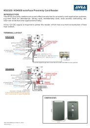
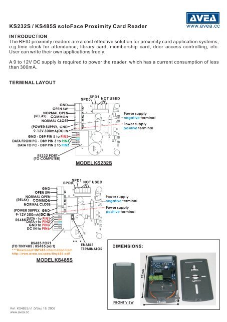
KS232S / <strong>KS485S</strong> soloFace Proximity Card Reader<br />
www.avea.cc<br />
INTRODUCTION<br />
The RFID proximity readers are a cost effective solution for proximity card application systems,<br />
e.g.time clock for attendance, library card, membership card, door access controlling, etc.<br />
User can write their own applications freely.<br />
A 9 to 12V DC supply is required to power the reader, which has a current consumption of less<br />
than 300mA.<br />
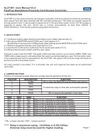
TERMINAL LAYOUT<br />
(RELA Y)<br />
OPE N SW<br />
NORMAL OPEN<br />
COMMON<br />
NORM AL CLOSE<br />
(POWER SUPPLY,<br />
9- 12V 300mA)<br />
GND<br />
GND<br />
DC<br />
IN<br />
GND - DB9 PIN 5 to PIN3<br />
DATA FRO M P C - DB9 PIN 3 to PIN4<br />
DATA TO PC - D B9 PIN 2 to PIN5<br />
PIN1<br />
PIN2<br />
PIN3<br />
PIN4<br />
PIN5<br />
PIN6<br />
PIN7<br />
PIN8<br />
SPD0 SPD1<br />
NOT USED<br />
Power supply<br />
negative terminal<br />
Power supply<br />
positive terminal<br />
RS232 PORT<br />
(TO COMPUTER)<br />
MODEL KS232S<br />
(RELA Y)<br />
OPEN SW<br />
NORMA L OPEN<br />
COMMON<br />
NORMAL CLOSE<br />
( POWER SUPPL Y,<br />
9- 12V 300mA)<br />
GND<br />
GND<br />
DC IN<br />
RS485<br />
DATA - to PIN1<br />
DATA+<br />
to PIN2<br />
GN D to PIN3<br />
DC I N to PIN6<br />
PIN1<br />
PIN2<br />
PIN3<br />
PIN4<br />
PIN5<br />
PIN6<br />
PIN7<br />
PIN8<br />
SPD0<br />
SPD1<br />
NOT USED<br />
Power supply<br />
negative terminal<br />
Power supply<br />
positive terminal<br />
RS485 PORT<br />
(TO TINY48 5 / RS485 port)<br />
*** Downloa d TINY485 informatio n from<br />
http ://www.ave a. cc/spe c/ tiny485. pdf<br />
MODEL <strong>KS485S</strong><br />
ENABLE<br />
TERMINATOR<br />
DIMENSIONS:<br />
57mm<br />
97mm<br />
9mm<br />
12mm<br />
FRONT VIEW<br />
57mm<br />
23.5mm<br />
Ref: <strong>KS485S</strong>/v1.0/Sep 18, 2008<br />
www.avea.cc
SETTINGS<br />
The communication speed can be set by SPD0 and SPD1. The frame format is 8 bit data, no<br />
parity, one start bit and one stop bit.<br />
SPD1 SPD0 FUNCTION<br />
Open Open 1200 bit/s.<br />
Open Close 9600 bit/s.<br />
Close Open 38400 bit/s.<br />
Close Close 115200 bit/s.<br />
* Default speed for KS232M is 1200 bit/s.<br />
Four communication formats are available, first 3 are ASCII based and the fourth is framed<br />
format. The default is format 3.<br />
FMT1 FMT0 FUNCTION<br />
1 1 Format 0, xxxxxxxxxxx (i.e. 11 digit + LF + CR)<br />
1 0 Format 1, xxx,xxxxx (i.e. 3 digit + comma + 5 digit + LF +<br />
CR)<br />
0 1 Format 2, xxxxx,xxxxxxxx (i.e. 5 digit + comma + 8 digit +<br />
LF + CR)<br />
0 0 Format 3, 0x02+0x06+n1+n2+n3+n4+n5+cs+0x03<br />
Where cs=n1+n2+n3+n4+n5<br />
BEEP FUNCTION MODE FUNCTION<br />
0 No Beep 0 Auto Repeat<br />
1 Auto Beep 1 No Repeat<br />
COMMUNICATION PROTOCOLS<br />
PC can send commands to the reader at any time and the reader will send back the response (if<br />
available). When the reader read a valid card, it will send the card code to the PC. The<br />
communication format from PC to reader is fixed. But there are four formats can be selected for<br />
reader to send to PC.<br />
Commands (From PC to reader):<br />
Command Hex Description<br />
~r 0x7e, 0x72 Turn off Relay<br />
~R 0x7e, 0x52 Turn on Relay<br />
~1 0x7e, 0x31 Pulse Relay for 1 second<br />
~2 0x7e, 0x32 Pulse Relay for 2 seconds<br />
~l 0x7e, 0x6c Turn off LED<br />
~L 0x7e, 0x4c Turn on LED<br />
~b 0x7e, 0x62 Turn off Buzzer<br />
~B 0x7e, 0x42 Turn on Buzzer<br />
~0 0x7e, 0x30 Make a beep sound<br />
~ 0x7e, 0x3f Inquire status<br />
~O 0x7e, 0x4f Inquire options<br />
~oX 0x7e, 0x6f, X Set options, where X=(0x41 + options) and option bit<br />
definitions are:<br />
Bit 0 – FMT 0<br />
Bit 1 – FMT 1<br />
Bit 2 – BEEP<br />
Bit 3 – MODE
ASCII RESPONSE (From reader to PC, format 0, 1 & 2)<br />
Response Hex Description<br />
‘RST’+LF+CR 0x52, 0x53, 0x54, Reader reset<br />
0x0a, 0x0d<br />
‘PO’+LF+CR 0x50, 0x4f, 0x0a, “OPEN SW” closed<br />
0x0d<br />
‘PF’+LF+CR 0x50, 0x46, 0x0a, “OPEN SW” opened<br />
0x0d<br />
‘S’+[s1]+[s2]+[s3]+[s4 0x53, s1, s2, s3, s4, Status response, where s1 to s4 can be ‘H’ or ‘L’ only<br />
]+CR+LF<br />
0x0a, 0x0d (0x48, 0x4c):<br />
S1 – switch state<br />
S2 – Red LED state<br />
‘s’+options+CR+LF<br />
0x73, options, 0x0a,<br />
0x0d<br />
Packet Response (From reader to PC, format 3)<br />
Response<br />
0x02, 0x02, 0x52, 0x52, 0x03 Reader reset<br />
0x02, 0x02, 0x50, 0x50, 0x03 Switch closed<br />
0x02, 0x02, 0x70, 0x70, 0x03 Switch opened<br />
S3 – Relay state<br />
Options response, where options=’A’+X, X ‘s bit<br />
definitions are:<br />
Bit 0 – FMT 0<br />
Bit 1 – FMT 1<br />
Bit 2 – BEEP<br />
Bit 3 – MODE<br />
Description<br />
0x02, 0x02, 0xfX, 0xfX, 0x03 Status response, where X ‘s bit definitions are:<br />
Bit 0 – switch state<br />
Bit 1 – Red LED state<br />
Bit 2 – Relay state<br />
Bit 3 – Buzzer state<br />
0x02, 0x02, 0xeX, 0xeX, 0x03 Status response, where X ‘s bit definitions are:<br />
Bit 0 – FMT 0<br />
Bit 1 – FMT 1<br />
Bit 2 – BEEP<br />
Bit 3 – MODE<br />
Test software isavailable from<br />
http://www.avea.cc/spec/test232.zip<br />
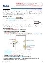
LOCK CONNECTION:<br />
Lock power<br />
Lock power<br />
Bypass<br />
switch<br />
C<br />
(COMMON)<br />
N.C.<br />
(NORMAL CLOSE)<br />
Electro-magnetic<br />
lock<br />
Lock power<br />
Bypass<br />
switch<br />
Lock power<br />
C<br />
(COMMON)<br />
N.O.<br />
(NORMAL OPEN)<br />
Electric<br />
Strike