KS485S user manual
KS485S user manual
KS485S user manual

You also want an ePaper? Increase the reach of your titles
YUMPU automatically turns print PDFs into web optimized ePapers that Google loves.
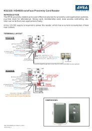
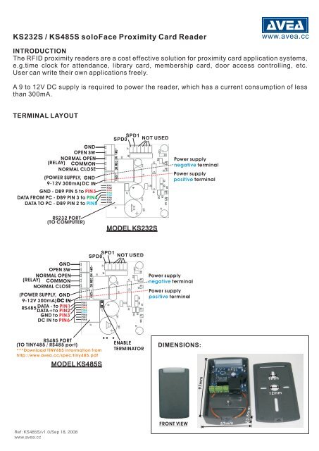
KS232S / <strong>KS485S</strong> soloFace Proximity Card Reader<br />
www.avea.cc<br />
INTRODUCTION<br />
The RFID proximity readers are a cost effective solution for proximity card application systems,<br />
e.g.time clock for attendance, library card, membership card, door access controlling, etc.<br />
User can write their own applications freely.<br />
A 9 to 12V DC supply is required to power the reader, which has a current consumption of less<br />
than 300mA.<br />
TERMINAL LAYOUT<br />
(RELA Y)<br />
OPE N SW<br />
NORMAL OPEN<br />
COMMON<br />
NORM AL CLOSE<br />
(POWER SUPPLY,<br />
9- 12V 300mA)<br />
GND<br />
GND<br />
DC<br />
IN<br />
GND - DB9 PIN 5 to PIN3<br />
DATA FRO M P C - DB9 PIN 3 to PIN4<br />
DATA TO PC - D B9 PIN 2 to PIN5<br />
PIN1<br />
PIN2<br />
PIN3<br />
PIN4<br />
PIN5<br />
PIN6<br />
PIN7<br />
PIN8<br />
SPD0 SPD1<br />
NOT USED<br />
Power supply<br />
negative terminal<br />
Power supply<br />
positive terminal<br />
RS232 PORT<br />
(TO COMPUTER)<br />
MODEL KS232S<br />
(RELA Y)<br />
OPEN SW<br />
NORMA L OPEN<br />
COMMON<br />
NORMAL CLOSE<br />
( POWER SUPPL Y,<br />
9- 12V 300mA)<br />
GND<br />
GND<br />
DC IN<br />
RS485<br />
DATA - to PIN1<br />
DATA+<br />
to PIN2<br />
GN D to PIN3<br />
DC I N to PIN6<br />
PIN1<br />
PIN2<br />
PIN3<br />
PIN4<br />
PIN5<br />
PIN6<br />
PIN7<br />
PIN8<br />
SPD0<br />
SPD1<br />
NOT USED<br />
Power supply<br />
negative terminal<br />
Power supply<br />
positive terminal<br />
RS485 PORT<br />
(TO TINY48 5 / RS485 port)<br />
*** Downloa d TINY485 informatio n from<br />
http ://www.ave a. cc/spe c/ tiny485. pdf<br />
MODEL <strong>KS485S</strong><br />
ENABLE<br />
TERMINATOR<br />
DIMENSIONS:<br />
57mm<br />
97mm<br />
9mm<br />
12mm<br />
FRONT VIEW<br />
57mm<br />
23.5mm<br />
Ref: <strong>KS485S</strong>/v1.0/Sep 18, 2008<br />
www.avea.cc
SETTINGS<br />
The communication speed can be set by SPD0 and SPD1. The frame format is 8 bit data, no<br />
parity, one start bit and one stop bit.<br />
SPD1 SPD0 FUNCTION<br />
Open Open 1200 bit/s.<br />
Open Close 9600 bit/s.<br />
Close Open 38400 bit/s.<br />
Close Close 115200 bit/s.<br />
* Default speed for KS232M is 1200 bit/s.<br />
Four communication formats are available, first 3 are ASCII based and the fourth is framed<br />
format. The default is format 3.<br />
FMT1 FMT0 FUNCTION<br />
1 1 Format 0, xxxxxxxxxxx (i.e. 11 digit + LF + CR)<br />
1 0 Format 1, xxx,xxxxx (i.e. 3 digit + comma + 5 digit + LF +<br />
CR)<br />
0 1 Format 2, xxxxx,xxxxxxxx (i.e. 5 digit + comma + 8 digit +<br />
LF + CR)<br />
0 0 Format 3, 0x02+0x06+n1+n2+n3+n4+n5+cs+0x03<br />
Where cs=n1+n2+n3+n4+n5<br />
BEEP FUNCTION MODE FUNCTION<br />
0 No Beep 0 Auto Repeat<br />
1 Auto Beep 1 No Repeat<br />
COMMUNICATION PROTOCOLS<br />
PC can send commands to the reader at any time and the reader will send back the response (if<br />
available). When the reader read a valid card, it will send the card code to the PC. The<br />
communication format from PC to reader is fixed. But there are four formats can be selected for<br />
reader to send to PC.<br />
Commands (From PC to reader):<br />
Command Hex Description<br />
~r 0x7e, 0x72 Turn off Relay<br />
~R 0x7e, 0x52 Turn on Relay<br />
~1 0x7e, 0x31 Pulse Relay for 1 second<br />
~2 0x7e, 0x32 Pulse Relay for 2 seconds<br />
~l 0x7e, 0x6c Turn off LED<br />
~L 0x7e, 0x4c Turn on LED<br />
~b 0x7e, 0x62 Turn off Buzzer<br />
~B 0x7e, 0x42 Turn on Buzzer<br />
~0 0x7e, 0x30 Make a beep sound<br />
~ 0x7e, 0x3f Inquire status<br />
~O 0x7e, 0x4f Inquire options<br />
~oX 0x7e, 0x6f, X Set options, where X=(0x41 + options) and option bit<br />
definitions are:<br />
Bit 0 – FMT 0<br />
Bit 1 – FMT 1<br />
Bit 2 – BEEP<br />
Bit 3 – MODE
ASCII RESPONSE (From reader to PC, format 0, 1 & 2)<br />
Response Hex Description<br />
‘RST’+LF+CR 0x52, 0x53, 0x54, Reader reset<br />
0x0a, 0x0d<br />
‘PO’+LF+CR 0x50, 0x4f, 0x0a, “OPEN SW” closed<br />
0x0d<br />
‘PF’+LF+CR 0x50, 0x46, 0x0a, “OPEN SW” opened<br />
0x0d<br />
‘S’+[s1]+[s2]+[s3]+[s4 0x53, s1, s2, s3, s4, Status response, where s1 to s4 can be ‘H’ or ‘L’ only<br />
]+CR+LF<br />
0x0a, 0x0d (0x48, 0x4c):<br />
S1 – switch state<br />
S2 – Red LED state<br />
‘s’+options+CR+LF<br />
0x73, options, 0x0a,<br />
0x0d<br />
Packet Response (From reader to PC, format 3)<br />
Response<br />
0x02, 0x02, 0x52, 0x52, 0x03 Reader reset<br />
0x02, 0x02, 0x50, 0x50, 0x03 Switch closed<br />
0x02, 0x02, 0x70, 0x70, 0x03 Switch opened<br />
S3 – Relay state<br />
Options response, where options=’A’+X, X ‘s bit<br />
definitions are:<br />
Bit 0 – FMT 0<br />
Bit 1 – FMT 1<br />
Bit 2 – BEEP<br />
Bit 3 – MODE<br />
Description<br />
0x02, 0x02, 0xfX, 0xfX, 0x03 Status response, where X ‘s bit definitions are:<br />
Bit 0 – switch state<br />
Bit 1 – Red LED state<br />
Bit 2 – Relay state<br />
Bit 3 – Buzzer state<br />
0x02, 0x02, 0xeX, 0xeX, 0x03 Status response, where X ‘s bit definitions are:<br />
Bit 0 – FMT 0<br />
Bit 1 – FMT 1<br />
Bit 2 – BEEP<br />
Bit 3 – MODE<br />
Test software isavailable from<br />
http://www.avea.cc/spec/test232.zip<br />
LOCK CONNECTION:<br />
Lock power<br />
Lock power<br />
Bypass<br />
switch<br />
C<br />
(COMMON)<br />
N.C.<br />
(NORMAL CLOSE)<br />
Electro-magnetic<br />
lock<br />
Lock power<br />
Bypass<br />
switch<br />
Lock power<br />
C<br />
(COMMON)<br />
N.O.<br />
(NORMAL OPEN)<br />
Electric<br />
Strike