User Network Interface (UNI) Requirements and Framework - MEF
User Network Interface (UNI) Requirements and Framework - MEF
User Network Interface (UNI) Requirements and Framework - MEF
Create successful ePaper yourself
Turn your PDF publications into a flip-book with our unique Google optimized e-Paper software.
<strong>UNI</strong> <strong>Requirements</strong> <strong>and</strong> <strong>Framework</strong><br />
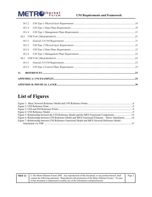
10.1.2 <strong>UNI</strong> Type 1 Physical layer <strong>Requirements</strong> .................................................................................................. 18<br />
10.1.3 <strong>UNI</strong> Type 1 Data Plane <strong>Requirements</strong> ....................................................................................................... 19<br />
10.1.4 <strong>UNI</strong> Type 1 Management Plane <strong>Requirements</strong> .......................................................................................... 21<br />
10.2 <strong>UNI</strong> TYPE 2 REQUIREMENTS .............................................................................................................................. 21<br />
10.2.1 General 2.0 <strong>UNI</strong> <strong>Requirements</strong> .................................................................................................................. 21<br />
10.2.2 <strong>UNI</strong> Type 2 Physical layer <strong>Requirements</strong> .................................................................................................. 22<br />
10.2.3 <strong>UNI</strong> Type 2 Data Plane <strong>Requirements</strong> ....................................................................................................... 22<br />
10.2.4 <strong>UNI</strong> Type 2 Management Plane <strong>Requirements</strong> .......................................................................................... 22<br />
10.3 <strong>UNI</strong> TYPE 3 REQUIREMENTS .............................................................................................................................. 23<br />
10.3.1 General 3.0 <strong>UNI</strong> <strong>Requirements</strong> .................................................................................................................. 23<br />
10.3.2 <strong>UNI</strong> Type 3 Control Plane <strong>Requirements</strong> .................................................................................................. 23<br />
11. REFERENCES .................................................................................................................................................... 23<br />
APPENDIX A: <strong>UNI</strong> EXAMPLES .................................................................................................................................. 25<br />
APPENDIX B: PHYSICAL LAYER ............................................................................................................................. 30<br />
List of Figures<br />
Figure 1: Basic <strong>Network</strong> Reference Model <strong>and</strong> <strong>UNI</strong> Reference Points........................................................................ 6<br />
Figure 2: <strong>UNI</strong> Reference Point ...................................................................................................................................... 8<br />
Figure 3: <strong>UNI</strong> <strong>and</strong> SNI Reference Points ...................................................................................................................... 8<br />
Figure 4: <strong>UNI</strong> Reference Model .................................................................................................................................... 9<br />
Figure 5: Relationship between the <strong>UNI</strong> Reference Model <strong>and</strong> the MEN Functional Components ............................ 13<br />
Figure 6: Relationship between <strong>UNI</strong> Reference Model <strong>and</strong> MEN Functional Elements – Direct Attachment ........... 14<br />
Figure 7: Relationship between <strong>UNI</strong> Reference Functional Model <strong>and</strong> MEN <strong>Network</strong> Reference Model –<br />
Attachment via TMF ........................................................................................................................................... 15<br />
<strong>MEF</strong> 11<br />
© The Metro Ethernet Forum 2005. Any reproduction of this document, or any portion thereof, shall<br />
contain the following statement: "Reproduced with permission of the Metro Ethernet Forum." No user<br />
of this document is authorized to modify any of the information contained herein.<br />
Page 3


