User Network Interface (UNI) Requirements and Framework - MEF
User Network Interface (UNI) Requirements and Framework - MEF
User Network Interface (UNI) Requirements and Framework - MEF

Create successful ePaper yourself
Turn your PDF publications into a flip-book with our unique Google optimized e-Paper software.
Technical Specification<br />
<strong>MEF</strong> 11<br />
<strong>User</strong> <strong>Network</strong> <strong>Interface</strong> (<strong>UNI</strong>) <strong>Requirements</strong> <strong>and</strong><br />
<strong>Framework</strong><br />
November 2004<br />
<strong>MEF</strong> 11<br />
© The Metro Ethernet Forum 2005. Any reproduction of this document, or any portion thereof, shall contain the<br />
following statement: "Reproduced with permission of the Metro Ethernet Forum." No user of this document is<br />
authorized to modify any of the information contained herein.
<strong>UNI</strong> <strong>Requirements</strong> <strong>and</strong> <strong>Framework</strong><br />
Disclaimer<br />
The information in this publication is freely available for reproduction <strong>and</strong> use by any recipient<br />
<strong>and</strong> is believed to be accurate as of its publication date. Such information is subject to change<br />
without notice <strong>and</strong> the Metro Ethernet Forum (<strong>MEF</strong>) is not responsible for any errors. The <strong>MEF</strong><br />
does not assume responsibility to update or correct any information in this publication. No<br />
representation or warranty, expressed or implied, is made by the <strong>MEF</strong> concerning the<br />
completeness, accuracy, or applicability of any information contained herein <strong>and</strong> no liability of<br />
any kind shall be assumed by the <strong>MEF</strong> as a result of reliance upon such information.<br />
The information contained herein is intended to be used without modification by the recipient or<br />
user of this document. The <strong>MEF</strong> is not responsible or liable for any modifications to this<br />
document made by any other party.<br />
The receipt or any use of this document or its contents does not in any way create, by implication<br />
or otherwise:<br />
(a) any express or implied license or right to or under any patent, copyright, trademark or<br />
trade secret rights held or claimed by any <strong>MEF</strong> member company which are or may be<br />
associated with the ideas, techniques, concepts or expressions contained herein; nor<br />
(b) any warranty or representation that any <strong>MEF</strong> member companies will announce any<br />
product(s) <strong>and</strong>/or service(s) related thereto, or if such announcements are made, that<br />
such announced product(s) <strong>and</strong>/or service(s) embody any or all of the ideas,<br />
technologies, or concepts contained herein; nor<br />
(c) any form of relationship between any <strong>MEF</strong> member companies <strong>and</strong> the recipient or<br />
user of this document.<br />
Implementation or use of specific Metro Ethernet st<strong>and</strong>ards or recommendations <strong>and</strong> <strong>MEF</strong><br />
specifications will be voluntary, <strong>and</strong> no company shall be obliged to implement them by virtue of<br />
participation in the Metro Ethernet Forum. The <strong>MEF</strong> is a non-profit international organization<br />
accelerating industry cooperation on Metro Ethernet technology. The <strong>MEF</strong> does not, expressly or<br />
otherwise, endorse or promote any specific products or services.<br />
© The Metro Ethernet Forum 2005. All Rights Reserved.<br />
<strong>MEF</strong> 11<br />
© The Metro Ethernet Forum 2005. Any reproduction of this document, or any portion thereof, shall<br />
contain the following statement: "Reproduced with permission of the Metro Ethernet Forum." No user<br />
of this document is authorized to modify any of the information contained herein.<br />
Page 1
<strong>UNI</strong> <strong>Requirements</strong> <strong>and</strong> <strong>Framework</strong><br />
Table of Contents<br />
ABSTRACT .......................................................................................................................................................................4<br />
1. TERMINOLOGY (NORMATIVE) .........................................................................................................................4<br />
2. SCOPE ........................................................................................................................................................................6<br />
3. COMPLIANCE LEVELS .........................................................................................................................................6<br />
4. <strong>UNI</strong> REFERENCE POINT .......................................................................................................................................7<br />
5. <strong>UNI</strong> REFERENCE MODEL ....................................................................................................................................9<br />
5.1 <strong>UNI</strong> DATA PLANE ................................................................................................................................................9<br />
5.1.1 Ethernet Frames at the <strong>UNI</strong> ....................................................................................................................... 10<br />
5.1.2 Tagging ...................................................................................................................................................... 10<br />
5.1.3 Traffic Management ................................................................................................................................... 10<br />
5.2 <strong>UNI</strong> CONTROL PLANE ........................................................................................................................................ 10<br />
5.3 <strong>UNI</strong> MANAGEMENT PLANE ................................................................................................................................ 11<br />
5.3.1 Provisioning <strong>and</strong> Static Service Discovery ................................................................................................ 11<br />
5.3.2 Protection <strong>and</strong> Restoration ........................................................................................................................ 12<br />
5.3.3 Operation, Administration <strong>and</strong> Maintenance (OAM) ................................................................................ 12<br />
6. RELATIONSHIP TO FUNCTIONAL ELEMENTS IN THE MEN ARCHITECTURE ................................. 12<br />
6.1 RELATIONSHIP TO TRAN LAYER(S) ................................................................................................................... 13<br />
6.1.1 Ethernet PHY as a TRAN component in the ETH Access Link .................................................................. 13<br />
6.1.2 TMF as a TRAN component in the ETH Access Link ................................................................................ 14<br />
7. <strong>UNI</strong> TYPES .............................................................................................................................................................. 15<br />
7.1 <strong>UNI</strong> TYPE 1 ........................................................................................................................................................ 15<br />
7.2 <strong>UNI</strong> TYPE 2 ........................................................................................................................................................ 15<br />
7.3 <strong>UNI</strong> TYPE 3 ........................................................................................................................................................ 16<br />
8. <strong>UNI</strong> SERVICE ATTRIBUTES............................................................................................................................... 16<br />
9. EVC SERVICE ATTRIBUTES ............................................................................................................................. 17<br />
10. <strong>UNI</strong> REQUIREMENTS ...................................................................................................................................... 17<br />
10.1 <strong>UNI</strong> TYPE 1 REQUIREMENTS .............................................................................................................................. 18<br />
10.1.1 General <strong>UNI</strong> Type 1 <strong>Requirements</strong> ............................................................................................................ 18<br />
<strong>MEF</strong> 11<br />
© The Metro Ethernet Forum 2005. Any reproduction of this document, or any portion thereof, shall<br />
contain the following statement: "Reproduced with permission of the Metro Ethernet Forum." No user<br />
of this document is authorized to modify any of the information contained herein.<br />
Page 2
<strong>UNI</strong> <strong>Requirements</strong> <strong>and</strong> <strong>Framework</strong><br />
10.1.2 <strong>UNI</strong> Type 1 Physical layer <strong>Requirements</strong> .................................................................................................. 18<br />
10.1.3 <strong>UNI</strong> Type 1 Data Plane <strong>Requirements</strong> ....................................................................................................... 19<br />
10.1.4 <strong>UNI</strong> Type 1 Management Plane <strong>Requirements</strong> .......................................................................................... 21<br />
10.2 <strong>UNI</strong> TYPE 2 REQUIREMENTS .............................................................................................................................. 21<br />
10.2.1 General 2.0 <strong>UNI</strong> <strong>Requirements</strong> .................................................................................................................. 21<br />
10.2.2 <strong>UNI</strong> Type 2 Physical layer <strong>Requirements</strong> .................................................................................................. 22<br />
10.2.3 <strong>UNI</strong> Type 2 Data Plane <strong>Requirements</strong> ....................................................................................................... 22<br />
10.2.4 <strong>UNI</strong> Type 2 Management Plane <strong>Requirements</strong> .......................................................................................... 22<br />
10.3 <strong>UNI</strong> TYPE 3 REQUIREMENTS .............................................................................................................................. 23<br />
10.3.1 General 3.0 <strong>UNI</strong> <strong>Requirements</strong> .................................................................................................................. 23<br />
10.3.2 <strong>UNI</strong> Type 3 Control Plane <strong>Requirements</strong> .................................................................................................. 23<br />
11. REFERENCES .................................................................................................................................................... 23<br />
APPENDIX A: <strong>UNI</strong> EXAMPLES .................................................................................................................................. 25<br />
APPENDIX B: PHYSICAL LAYER ............................................................................................................................. 30<br />
List of Figures<br />
Figure 1: Basic <strong>Network</strong> Reference Model <strong>and</strong> <strong>UNI</strong> Reference Points........................................................................ 6<br />
Figure 2: <strong>UNI</strong> Reference Point ...................................................................................................................................... 8<br />
Figure 3: <strong>UNI</strong> <strong>and</strong> SNI Reference Points ...................................................................................................................... 8<br />
Figure 4: <strong>UNI</strong> Reference Model .................................................................................................................................... 9<br />
Figure 5: Relationship between the <strong>UNI</strong> Reference Model <strong>and</strong> the MEN Functional Components ............................ 13<br />
Figure 6: Relationship between <strong>UNI</strong> Reference Model <strong>and</strong> MEN Functional Elements – Direct Attachment ........... 14<br />
Figure 7: Relationship between <strong>UNI</strong> Reference Functional Model <strong>and</strong> MEN <strong>Network</strong> Reference Model –<br />
Attachment via TMF ........................................................................................................................................... 15<br />
<strong>MEF</strong> 11<br />
© The Metro Ethernet Forum 2005. Any reproduction of this document, or any portion thereof, shall<br />
contain the following statement: "Reproduced with permission of the Metro Ethernet Forum." No user<br />
of this document is authorized to modify any of the information contained herein.<br />
Page 3
<strong>UNI</strong> <strong>Requirements</strong> <strong>and</strong> <strong>Framework</strong><br />
Abstract<br />
This document describes the <strong>User</strong> to <strong>Network</strong> <strong>Interface</strong> (<strong>UNI</strong>) <strong>Requirements</strong> <strong>and</strong> <strong>Framework</strong>. It<br />
provides requirements, framework <strong>and</strong> functional model on how the <strong>UNI</strong> reference point will<br />
operate in a Metro Ethernet <strong>Network</strong> (MEN).<br />
1. Terminology (Normative)<br />
Term<br />
All to One Bundling<br />
B<strong>and</strong>width Profile<br />
Broadcast Service<br />
Frame<br />
Bundling<br />
CBS<br />
CE<br />
CE-VLAN CoS<br />
CE-VLAN ID<br />
CE-VLAN ID<br />
Preservation<br />
CE-VLAN ID/EVC<br />
Map<br />
CE-VLAN Tag<br />
CIR<br />
Class of Service<br />
Committed Burst Size<br />
Committed<br />
Information Rate<br />
Customer Edge<br />
Customer Edge<br />
VLAN CoS<br />
Customer Edge<br />
VLAN ID<br />
Customer Edge<br />
Definition<br />
A <strong>UNI</strong> attribute in which all CE-VLAN IDs are associated with a<br />
single EVC.<br />
A method of classifying a particular set of Service Frames based on<br />
the b<strong>and</strong>width used by the frames at the <strong>UNI</strong>.<br />
A Service Frame that has a broadcast destination MAC address.<br />
A <strong>UNI</strong> attribute in which more than one CE-VLAN ID is associated<br />
with an EVC.<br />
Committed Burst Size<br />
Customer Edge<br />
Customer Edge VLAN CoS<br />
Customer Edge VLAN ID<br />
An EVC attribute in which the CE-VLAN ID of an egress Service<br />
Frame is identical in value to the CE-VLAN ID of the corresponding<br />
ingress Service Frame.<br />
An association of CE-VLAN IDs <strong>and</strong> EVCs at a <strong>UNI</strong>.<br />
Customer Edge VLAN Tag<br />
Committed Information Rate<br />
A set of Service Frames that have a commitment from the Service<br />
Provider to receive a particular level of performance.<br />
A measure of the amount of bytes sent in back-to-back Service<br />
Frames at the <strong>UNI</strong>.<br />
A measure of long term average bit rate for a set of Service Frames<br />
with at the <strong>UNI</strong>.<br />
Equipment on the Subscriber side of the <strong>UNI</strong>.<br />
The Subscriber_priority bits in the IEEE 802.1Q Tag in a tagged<br />
Service Frame.<br />
The identity of the VLANs on the Ethernet port of the customer<br />
equipment that is attached to the <strong>UNI</strong>.<br />
The IEEE 802.1Q Tag in a tagged Service Frame. When present it<br />
<strong>MEF</strong> 11<br />
© The Metro Ethernet Forum 2005. Any reproduction of this document, or any portion thereof, shall<br />
contain the following statement: "Reproduced with permission of the Metro Ethernet Forum." No user<br />
of this document is authorized to modify any of the information contained herein.<br />
Page 4
<strong>UNI</strong> <strong>Requirements</strong> <strong>and</strong> <strong>Framework</strong><br />
Term<br />
VLAN Tag<br />
Egress Frame<br />
Ethernet Virtual<br />
Connection<br />
EVC<br />
Frame<br />
Frame Delay<br />
Frame Jitter<br />
Frame Loss<br />
Ingress Frame<br />
Layer 2 Control<br />
Protocol Service<br />
Frame<br />
Layer 2 Control<br />
Protocol Tunneling<br />
Multicast Service<br />
Frame<br />
Multipoint-to-<br />
Multipoint EVC<br />
EBS<br />
Excess Burst Size<br />
Excess Information<br />
Rate<br />
EIR<br />
Point-to-Point EVC<br />
Service Frame<br />
Service Multiplexing<br />
Service Provider<br />
Subscriber<br />
<strong>UNI</strong><br />
<strong>UNI</strong>-EVC<br />
<strong>UNI</strong>-EVCID<br />
Unicast Service<br />
Definition<br />
contains the Customer Edge VLAN ID.<br />
A frame sent from the Service Provider network to the CE.<br />
An association of two or more <strong>UNI</strong>s that limits the exchange of<br />
frames to <strong>UNI</strong>s in the Ethernet Virtual Connection<br />
Ethernet Virtual Connection<br />
Short for Ethernet frame.<br />
A performance attribute of an EVC.<br />
A performance attribute of an EVC.<br />
A performance attribute of an EVC.<br />
A frame sent from the CE into the Service Provider network.<br />
A Service Frame that is used for Layer 2 control, e.g., Spanning<br />
Tree Protocol.<br />
The process by which a Layer 2 Control Protocol Service Frame is<br />
passed through the Service Provider network switches without being<br />
processed by those switches <strong>and</strong> delivered to the proper <strong>UNI</strong>(s).<br />
A Service Frame that has a multicast destination MAC address.<br />
An EVC with two or more <strong>UNI</strong>s.<br />
Excess Burst Size<br />
A measure of the amount of bytes sent in back-to-back Service<br />
Frames at the <strong>UNI</strong>.<br />
A measure of long term average bit rate for a set of Service Frames<br />
at the <strong>UNI</strong>.<br />
Excess Information Rate<br />
An EVC with exactly 2 <strong>UNI</strong>s.<br />
An Ethernet frame transmitted across the <strong>UNI</strong> toward the Service<br />
Provider or an Ethernet frame transmitted across the <strong>UNI</strong> toward the<br />
Subscriber.<br />
A <strong>UNI</strong> attribute in which the <strong>UNI</strong> can be in more than one EVC<br />
instance.<br />
The organization providing Ethernet Service(s).<br />
The organization purchasing <strong>and</strong>/or using Ethernet Services.<br />
<strong>User</strong> <strong>Network</strong> <strong>Interface</strong><br />
The part of the EVC between the <strong>UNI</strong>-N <strong>and</strong> <strong>UNI</strong>-C<br />
The ID that identifies the part of the EVC between the <strong>UNI</strong>-N <strong>and</strong><br />
<strong>UNI</strong>-C. This can be derived from CE-VLAN ID, Physical Port,<br />
TRANS Tag or combination of these.<br />
A Service Frame that has a Unicast destination MAC address.<br />
<strong>MEF</strong> 11<br />
© The Metro Ethernet Forum 2005. Any reproduction of this document, or any portion thereof, shall<br />
contain the following statement: "Reproduced with permission of the Metro Ethernet Forum." No user<br />
of this document is authorized to modify any of the information contained herein.<br />
Page 5
<strong>UNI</strong> <strong>Requirements</strong> <strong>and</strong> <strong>Framework</strong><br />
Term<br />
Frame<br />
<strong>User</strong> <strong>Network</strong><br />
<strong>Interface</strong><br />
Definition<br />
The physical demarcation point between the responsibility of the<br />
Service Provider <strong>and</strong> the responsibility of the Subscriber<br />
2. Scope<br />
This document provides a framework <strong>and</strong> requirements for the <strong>MEF</strong> ETH-layer <strong>UNI</strong>. The <strong>UNI</strong> is<br />
a demarcation point between the responsibility of the Service Provider <strong>and</strong> the responsibility of<br />
the Subscriber. The <strong>MEF</strong> <strong>UNI</strong> is a reference point for all interactions between Subscribers of<br />
<strong>MEF</strong> defined services <strong>and</strong> the MEN Service Provider.<br />
The <strong>UNI</strong> is physically implemented over a bi-directional ETH link that provides the various data,<br />
control <strong>and</strong> management plane capabilities required by the MEN Service Provider to clearly<br />
demarcate the two different network domains involved in the operational, administrative,<br />
maintenance <strong>and</strong> provisioning aspects of the service.<br />
This document describes the different functional components that are used to implement these<br />
control, data <strong>and</strong> management plane aspects related to <strong>MEF</strong> <strong>UNI</strong>. These functional components<br />
can be specified in subsequent <strong>UNI</strong> Implementation Agreements(s). The actual implementations<br />
<strong>and</strong> protocols used to implement <strong>UNI</strong> functional components are out of scope for this document.<br />
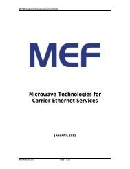
<strong>MEF</strong> <strong>UNI</strong> references the Basic <strong>Network</strong> Reference Model of <strong>MEF</strong> 4 [8]. The model depicted<br />
below identifies the <strong>UNI</strong> Reference Points.<br />
Subscriber<br />
S<br />
Private<br />
Customer<br />
<strong>Network</strong><br />
<strong>UNI</strong><br />
Metro<br />
Ethernet<br />
<strong>Network</strong><br />
(MEN)<br />
<strong>UNI</strong><br />
Private<br />
Customer<br />
<strong>Network</strong><br />
Subscriber<br />
S<br />
Enduser<br />
Enduser<br />
Ethernet Virtual Connection<br />
Figure 1: Basic <strong>Network</strong> Reference Model <strong>and</strong> <strong>UNI</strong> Reference Points<br />
3. Compliance Levels<br />
The key words “MUST”, “MUST NOT”, “REQUIRED”, “SHALL”, “SHALL NOT”,<br />
“SHOULD”, “SHOULD NOT”, “RECOMMENDED”, “MAY”, <strong>and</strong> “OPTIONAL” in this<br />
<strong>MEF</strong> 11<br />
© The Metro Ethernet Forum 2005. Any reproduction of this document, or any portion thereof, shall<br />
contain the following statement: "Reproduced with permission of the Metro Ethernet Forum." No user<br />
of this document is authorized to modify any of the information contained herein.<br />
Page 6
<strong>UNI</strong> <strong>Requirements</strong> <strong>and</strong> <strong>Framework</strong><br />
document are to be interpreted as described in RFC 2119 [1]. All key words use upper case, bold<br />
text.<br />
4. <strong>UNI</strong> Reference Point<br />
The <strong>UNI</strong> describes different aspects of the interface between the Subscriber <strong>and</strong> Service<br />
Provider. The <strong>UNI</strong> is physically implemented over a bi-directional ETH link that provides the<br />
various data, control <strong>and</strong> management plane capabilities required by the MEN Service Provider<br />
to clearly demarcate the two different network domains involved in the operational,<br />
administrative, maintenance <strong>and</strong> provisioning aspects of the service. The control, data <strong>and</strong><br />
management plane aspects that relate to this interface are implemented via various functional<br />
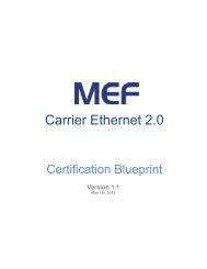
components. As illustrated in Figure 2, the <strong>UNI</strong> Reference Point provides the demarcation<br />
between a Subscriber <strong>and</strong> the MEN boundaries. The <strong>UNI</strong> Reference Point is typically located at<br />
the Subscriber premises <strong>and</strong> is always at connector where the Subscriber network connects the<br />
Service Provider network.<br />
The <strong>UNI</strong> functionality is split between the Subscriber's functions, called <strong>UNI</strong>-C, <strong>and</strong> the MEN<br />
functions, called <strong>UNI</strong>-N. Because of the distributed nature of the <strong>UNI</strong>, <strong>UNI</strong>-C <strong>and</strong> <strong>UNI</strong>-N<br />
maintenance is necessarily performed by different autonomies. The MEN Service Provider is<br />
responsible for <strong>UNI</strong>-N, i.e. all aspects of the <strong>UNI</strong> from the Provider Edge to the <strong>UNI</strong> Reference<br />
Point. The <strong>UNI</strong>-N is used to refer to a set of one or more functional elements that supports the<br />
MEN Service Provider’s technical capabilities <strong>and</strong> compliance to the <strong>UNI</strong> specification. The<br />
MEN Subscriber is responsible for <strong>UNI</strong>-C, i.e. all aspects of the <strong>UNI</strong> from the Customer Edge<br />
(CE) device to the <strong>UNI</strong> Reference Point. The <strong>UNI</strong>-C refers to the functional elements within the<br />
CE that supports the MEN Subscriber’s technical capabilities <strong>and</strong> compliance to the <strong>UNI</strong><br />
specification.<br />
<strong>MEF</strong> 11<br />
© The Metro Ethernet Forum 2005. Any reproduction of this document, or any portion thereof, shall<br />
contain the following statement: "Reproduced with permission of the Metro Ethernet Forum." No user<br />
of this document is authorized to modify any of the information contained herein.<br />
Page 7
<strong>UNI</strong> <strong>Requirements</strong> <strong>and</strong> <strong>Framework</strong><br />
Customer<br />
<strong>Network</strong><br />
Subscriber<br />
Edge<br />
(CE)<br />
Ethernet<br />
PHY<br />
Provider<br />
Edge<br />
MEN<br />
<strong>UNI</strong>-C<br />
<strong>UNI</strong>-N<br />
<strong>UNI</strong> Reference Point<br />
Figure 2: <strong>UNI</strong> Reference Point<br />
The <strong>UNI</strong>-C is always connected to the <strong>UNI</strong> Reference Point by an IEEE 802.3 PHY. The <strong>UNI</strong>-<br />
N functional components which implement the Service Provider side of the <strong>UNI</strong> functions may<br />
be distributed over an access network. The reference point between the access network <strong>and</strong> the<br />
Provider Edge (PE) equipment is called Service Node <strong>Interface</strong> (SNI). In the simplest case where<br />
the access network is an Ethernet 802.3 PHY <strong>and</strong> <strong>UNI</strong>-C <strong>and</strong> <strong>UNI</strong>-N are connected to the <strong>UNI</strong><br />
Reference Point by an IEEE 802.3 PHY, the <strong>UNI</strong> <strong>and</strong> SNI Reference Points are coincident. The<br />
<strong>UNI</strong> <strong>and</strong> SNI Reference Points are analogous to the T(TB) <strong>and</strong> V(VB) reference points used in<br />
ISDN <strong>and</strong> B-ISDN terminology. The SNI Reference Point is beyond the scope of this<br />
framework.<br />
<strong>UNI</strong><br />
SNI<br />
Subscriber A<br />
Subscriber B<br />
<strong>UNI</strong><br />
Access<br />
<strong>Network</strong><br />
Metro<br />
Ethernet<br />
<strong>Network</strong><br />
Figure 3: <strong>UNI</strong> <strong>and</strong> SNI Reference Points<br />
<strong>MEF</strong> 11<br />
© The Metro Ethernet Forum 2005. Any reproduction of this document, or any portion thereof, shall<br />
contain the following statement: "Reproduced with permission of the Metro Ethernet Forum." No user<br />
of this document is authorized to modify any of the information contained herein.<br />
Page 8
<strong>UNI</strong> <strong>Requirements</strong> <strong>and</strong> <strong>Framework</strong><br />
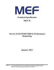
5. <strong>UNI</strong> Reference Model<br />
This section gives an overview of the different building blocks that constitute the <strong>UNI</strong> functions,<br />
<strong>and</strong> describes the various layers, capabilities <strong>and</strong> processes that are part of each building block.<br />
<strong>UNI</strong> Reference Model is shown in Figure 4.<br />
<strong>UNI</strong> Data Plane<br />
• Ethernet Frames<br />
• Tagging<br />
• Traffic Management<br />
<strong>UNI</strong> Control Plane<br />
• Connection signaling<br />
<strong>and</strong> control<br />
<strong>UNI</strong> Management Plane<br />
• Provisioning<br />
• Static Service Discovery<br />
• Protection & Restoration<br />
• OAM<br />
Figure 4: <strong>UNI</strong> Reference Model<br />
The <strong>UNI</strong> Reference Model consists of three planes:<br />
• The <strong>UNI</strong> data plane, which defines the means of transporting information across the<br />
<strong>UNI</strong> reference point;<br />
• The <strong>UNI</strong> control plane, which defines the means for the Subscriber <strong>and</strong> the MEN<br />
Service Provider to communicate to make use of the <strong>UNI</strong> data plane;<br />
• The <strong>UNI</strong> management plane, which configures <strong>and</strong> monitors the operation of the <strong>UNI</strong><br />
data <strong>and</strong> control plane.<br />
Figure 4 also shows a number of specific functional capabilities <strong>and</strong> the planes to which they<br />
typically belong. Note that several of these functional capabilities are closely related with<br />
functional capabilities in other planes of the <strong>UNI</strong> Reference Model.<br />
Each of these planes <strong>and</strong> their associated functionality will now be discussed in more detail.<br />
5.1 <strong>UNI</strong> DATA PLANE<br />
The <strong>UNI</strong> data plane consists of the mechanisms used to transport various Subscriber Service<br />
Frame flows, including Subscribe data, control <strong>and</strong> management frames, across the <strong>UNI</strong><br />
reference point. For the purposes of the Ethernet <strong>UNI</strong>, all Service Frame flows are associated<br />
with on IEEE 802.3/Ethernet frames.<br />
<strong>MEF</strong> 11<br />
© The Metro Ethernet Forum 2005. Any reproduction of this document, or any portion thereof, shall<br />
contain the following statement: "Reproduced with permission of the Metro Ethernet Forum." No user<br />
of this document is authorized to modify any of the information contained herein.<br />
Page 9
<strong>UNI</strong> <strong>Requirements</strong> <strong>and</strong> <strong>Framework</strong><br />
The <strong>UNI</strong> data plane includes the definition of the physical <strong>and</strong> data link layer. The physical layer<br />
is based on an IEEE 802.3 PHY. Other physical layers may be considered, provided that they<br />
can transport Ethernet frames over the <strong>UNI</strong> reference point in a transparent manner.<br />
5.1.1 Ethernet Frames at the <strong>UNI</strong><br />
The physical <strong>and</strong> data link layers across the <strong>UNI</strong> will be based on the IEEE 802.3/Ethernet PHY<br />
& MAC. The Subscriber <strong>and</strong> Service Provider are expected to send only Ethernet frames across<br />
the <strong>UNI</strong>.<br />
5.1.2 Tagging<br />
Ethernet frames may be tagged by the subscriber using IEEE 802.1Q [5] VLAN tags (CE-VLAN<br />
ID) before entering the MEN. The MEN Service Provider could use tagging for traffic<br />
management <strong>and</strong> Subscriber traffic segregation purposes. Tagging of ingress frames by the<br />
Service Provider is based on the CE VLAN ID [7].<br />
When a Service Provider tagged Ethernet frame is sent from inside the MEN to the Subscriber,<br />
the <strong>UNI</strong>-N ensures that the egress frame has the correct CE-VLAN ID. The specific format of<br />
the frame at the <strong>UNI</strong> depends on the Service Provider policies that are under control of the<br />
management plane.<br />
The Ethernet <strong>UNI</strong> is typically not concerned with any other higher layer protocol data units<br />
(PDUs) contained in the Ethernet frame. Unless otherwise specified (as part of a client-specific<br />
Ethernet <strong>UNI</strong>-C function) this higher-layer information may be h<strong>and</strong>led by other higher-layer<br />
<strong>UNI</strong>s.<br />
5.1.3 Traffic Management<br />
The Subscriber may be provided with one or more classes of service determined by the CE-<br />
VLAN CoS [7] values for a given service. Different traffic management functions may be<br />
applied to the different classes of service determined by the CE-VLAN CoS value. For more<br />
details on traffic management parameters, refer to [9].<br />
5.2 <strong>UNI</strong> CONTROL PLANE<br />
In order for a Subscriber to make use of one or more Ethernet services, a communication<br />
mechanism may be required between the Subscriber <strong>and</strong> the MEN Service Provider. This<br />
communication mechanism may be either in-b<strong>and</strong> or out-of-b<strong>and</strong>. The communications<br />
mechanism is defined as part of the <strong>UNI</strong> control plane.<br />
<strong>MEF</strong> 11<br />
© The Metro Ethernet Forum 2005. Any reproduction of this document, or any portion thereof, shall<br />
contain the following statement: "Reproduced with permission of the Metro Ethernet Forum." No user<br />
of this document is authorized to modify any of the information contained herein.<br />
Page 10
<strong>UNI</strong> <strong>Requirements</strong> <strong>and</strong> <strong>Framework</strong><br />
The <strong>UNI</strong> control plane defines the means for the Subscriber <strong>and</strong> the MEN Service Provider to<br />
agree on which Ethernet service(s) will be offered <strong>and</strong> on the characteristics of this service. More<br />
specifically, it defines the means to agree on how the Subscriber <strong>and</strong> the MEN Service Provider<br />
will make use of the <strong>UNI</strong> data plane. Both will be subject to a bilateral contract: the Subscriber<br />
should comply with the Ethernet service specification, <strong>and</strong> the MEN Service Provider must<br />
satisfy the commitments in the offered Ethernet service.<br />
The <strong>UNI</strong> control plane functionality may include a dynamic connection setup function that<br />
allows dynamic establishment of Ethernet services. Unlike the static service discovery model<br />
(see section 5.3.1), the Service Provider can provision the network at the time the service request<br />
is received from the Subscriber. This obviously increases the complexity of the service activation<br />
process, but increases configuration flexibility <strong>and</strong> manageability to the Subscriber. This<br />
mechanism could also be used to change the characteristics of an established Ethernet service.<br />
5.3 <strong>UNI</strong> MANAGEMENT PLANE<br />
The <strong>UNI</strong> management plane configures <strong>and</strong> monitors the operation of both the <strong>UNI</strong> data <strong>and</strong><br />
control plane. It includes the provisioning <strong>and</strong> management steps that need to be taken in order<br />
for the <strong>UNI</strong> data plane to support the Ethernet service. The management plane also controls how<br />
the control plane may operate, i.e., it controls when static service discovery <strong>and</strong>/or dynamic<br />
connection setup are allowed. Static service discovery function allows auto-configuration of the<br />
CE.<br />
5.3.1 Provisioning <strong>and</strong> Static Service Discovery<br />
In order for the Subscriber to make use of an Ethernet service, the MEN Service Provider needs<br />
to make sure that his network is correctly provisioned to satisfy the service needs. This process<br />
includes configuration of involved MEN network elements <strong>and</strong> associated CEs based on the<br />
service attributes. The management plane performs this task.<br />
The management plane may interact with a network management system in the MEN domain<br />
that determines which configuration should be used for a particular Subscriber. Static<br />
configuration of the <strong>UNI</strong> makes use of management interfaces, such as the one defined in the<br />
<strong>MEF</strong> 7 [11]. The Subscriber’s equipment can be provisioned with the service-specific parameters<br />
either manually or automatically via a static service discovery function. The static service<br />
discovery function allows the <strong>UNI</strong>-C to statically retrieve the needed configuration information<br />
from the <strong>UNI</strong>-N. In this manner, the Ethernet services may be activated without manual<br />
configuration intervention by the Subscriber. The process is static in the sense that the service is<br />
already provisioned by the MEN Service Provider, <strong>and</strong> does not require further provisioning<br />
information from the Subscriber at the time the Subscriber retrieves the configuration parameters<br />
from the <strong>UNI</strong>-N.<br />
<strong>MEF</strong> 11<br />
© The Metro Ethernet Forum 2005. Any reproduction of this document, or any portion thereof, shall<br />
contain the following statement: "Reproduced with permission of the Metro Ethernet Forum." No user<br />
of this document is authorized to modify any of the information contained herein.<br />
Page 11
<strong>UNI</strong> <strong>Requirements</strong> <strong>and</strong> <strong>Framework</strong><br />
QoS management is a subset of the service provisioning functions. It specifically includes the<br />
provisioning of service attributes <strong>and</strong> characteristics of traffic policer, shapers, etc. This process<br />
enables the correct behavior in the <strong>UNI</strong> data plane <strong>and</strong> the Ethernet service activation.<br />
5.3.2 Protection <strong>and</strong> Restoration<br />
Although more important inside the MEN domain, protection <strong>and</strong> restoration could also play a<br />
role between the <strong>UNI</strong>-C <strong>and</strong> the <strong>UNI</strong>-N. For example, a Subscriber may have two physical links<br />
activated towards the MEN as part of the same Ethernet service. Depending on the service<br />
characteristics, interaction between the management planes of both links may be required. For<br />
instance, if one link fails, the other link could take over. If load balancing is performed over both<br />
links under normal operation (e.g. 50% traffic in each link), upon failure of one link the failed<br />
link’s traffic can be carried across the remaining active link.<br />
This function is closely related to the OAM function described below.<br />
5.3.3 Operation, Administration <strong>and</strong> Maintenance (OAM)<br />
OAM is the process that is primarily concerned with fault <strong>and</strong> performance management. This<br />
process includes:<br />
• connectivity verification, to make sure Ethernet traffic can be sent over the <strong>UNI</strong>;<br />
• performance monitoring, to assert the extent to which errors have occurred across the<br />
<strong>UNI</strong>;<br />
• statistics gathering of the number of frames successfully sent, as well as lost or corrupted<br />
frames for SLS verification purposes.<br />
• fault indication, informing the far end that a fault condition is present on the <strong>UNI</strong>.<br />
In order to achieve these functions, an OAM management plane is required between the <strong>UNI</strong>-C<br />
<strong>and</strong> the <strong>UNI</strong>-N. This plane is provided over the Ethernet link as illustrated in Figure 2.<br />
6. Relationship to Functional Elements in the MEN Architecture<br />
The relationship between the <strong>UNI</strong> Reference Model <strong>and</strong> the MEN Functional Elements is<br />
depicted in Figure 5. The <strong>UNI</strong> Reference Model specifies the sub-set of functional capabilities<br />
supported by the <strong>UNI</strong>-C <strong>and</strong> the <strong>UNI</strong>-N to operate, administer, manage <strong>and</strong> provision the service<br />
across Subscriber to MEN boundaries. In this model, the <strong>UNI</strong>-C <strong>and</strong> <strong>UNI</strong>-N are specified as a set<br />
of one or more functional elements that support the necessary functions of the <strong>UNI</strong>. The<br />
relationship between the physical connectivity between the <strong>UNI</strong>-C <strong>and</strong> the <strong>UNI</strong>-N <strong>and</strong> TRAN<br />
<strong>MEF</strong> 11<br />
© The Metro Ethernet Forum 2005. Any reproduction of this document, or any portion thereof, shall<br />
contain the following statement: "Reproduced with permission of the Metro Ethernet Forum." No user<br />
of this document is authorized to modify any of the information contained herein.<br />
Page 12
<strong>UNI</strong> <strong>Requirements</strong> <strong>and</strong> <strong>Framework</strong><br />
Layer is described in Section 6.1. Subscriber to Subscriber service frames (including<br />
Subscriber’s data, control <strong>and</strong> management frames) are h<strong>and</strong>led by <strong>UNI</strong>-C <strong>and</strong> <strong>UNI</strong>-N data plane<br />
functional elements. Control frames between Subscriber <strong>and</strong> Service Provider are h<strong>and</strong>led by<br />
<strong>UNI</strong>-C <strong>and</strong> <strong>UNI</strong>-N control plane functional elements. Management frames between Subscriber<br />
<strong>and</strong> Service Provider are h<strong>and</strong>led by <strong>UNI</strong>-C <strong>and</strong> <strong>UNI</strong>-N management plane functional elements.<br />
EMS <strong>Interface</strong><br />
Management<br />
Management<br />
plane<br />
ETH Access Link<br />
Management<br />
Management<br />
plane<br />
ETH Trunk<br />
Links<br />
Data plane Cont<br />
Control<br />
plane<br />
plane<br />
Control<br />
Control<br />
plane<br />
Data Data plane<br />
plane<br />
<strong>UNI</strong>-C<br />
<strong>UNI</strong><br />
Reference<br />
Point<br />
Service Frame Flow<br />
<strong>UNI</strong>-N<br />
Figure 5: Relationship between the <strong>UNI</strong> Reference Model <strong>and</strong> the MEN Functional<br />
Components<br />
6.1 RELATIONSHIP TO TRAN LAYER(S)<br />
The physical layer at <strong>UNI</strong> Reference Point is defined to be an IEEE 802.3 PHY, as mentioned in<br />
Appendix B. The types of TRAN components are defined here that can be used to provide<br />
transport connectivity between the <strong>UNI</strong>-C <strong>and</strong> <strong>UNI</strong>-N which comprises the ETH Access Link<br />
[8]. The section below defines the various types of <strong>UNI</strong> configurations that are permissible.<br />
6.1.1 Ethernet PHY as a TRAN component in the ETH Access Link<br />
Figure 6 illustrates the relationship between the <strong>UNI</strong> Reference Model <strong>and</strong> other Functional<br />
Elements in the MEN Architecture when the <strong>UNI</strong>-C is directly attached to the <strong>UNI</strong>-N via a<br />
point-to-point Ethernet PHY TRAN link. The ETH Access Link is an abstract link which is<br />
composed of TRAN Layer components (in this case Ethernet PHYs) <strong>and</strong> ETH Layer<br />
components. There may be one or more EVCs h<strong>and</strong>led by <strong>UNI</strong>-N. The EVC for each Ethernet<br />
Service Frame is identified by the CE-VLAN ID of the service frame <strong>and</strong> the CE-VLAN<br />
ID/EVC Map [7]. The <strong>UNI</strong>-N <strong>and</strong> the <strong>UNI</strong>-C need to be configured with the same CE-VLAN<br />
ID/EVC Map values.<br />
<strong>MEF</strong> 11<br />
© The Metro Ethernet Forum 2005. Any reproduction of this document, or any portion thereof, shall<br />
contain the following statement: "Reproduced with permission of the Metro Ethernet Forum." No user<br />
of this document is authorized to modify any of the information contained herein.<br />
Page 13
<strong>UNI</strong> <strong>Requirements</strong> <strong>and</strong> <strong>Framework</strong><br />
EMS <strong>Interface</strong><br />
Management<br />
Management<br />
plane<br />
ETH Access Link<br />
Management<br />
Management<br />
plane<br />
Data plane Cont<br />
Control<br />
plane<br />
plane<br />
ETH Layer<br />
Service Frame Flow<br />
Control<br />
Control<br />
plane<br />
Data Data<br />
plane<br />
<strong>UNI</strong>-C<br />
TRAN TRAIL<br />
TRAN Layer<br />
<strong>UNI</strong>-N<br />
<strong>UNI</strong> Reference<br />
Point<br />
Figure 6: Relationship between <strong>UNI</strong> Reference Model <strong>and</strong> MEN Functional Elements –<br />
Direct Attachment<br />
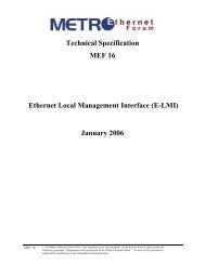
6.1.2 TMF as a TRAN component in the ETH Access Link<br />
Figure 7 illustrates the relationship between the <strong>UNI</strong> Reference Model <strong>and</strong> MEN Functional<br />
Elements when the <strong>UNI</strong>-C is attached to the <strong>UNI</strong>-N via a TRAN Multiplexed Link provided by a<br />
TMF (Transport Multiplexing Function).<br />
The TMF provides the multiplexing of several ETH Access Links over a single TRAN<br />
Multiplexed Link that terminates at the PE. Since each <strong>UNI</strong>-C instance is related to a specific<br />
CE, it is necessary to relate each <strong>UNI</strong>-C to a specific ETH Access Link at the <strong>UNI</strong>-N via a<br />
TRAN tag that defines the relationship of the ETH Access Link <strong>and</strong> the location within the<br />
TRAN Multiplexed Link. This is done by using a TMF tag at the TRAN Multiplexed Link<br />
(between the TMF <strong>and</strong> <strong>UNI</strong>-N) as a logical identifier that defines the ETH Access Link <strong>and</strong><br />
therefore the respective <strong>UNI</strong>-C. As indicated in<br />
Figure 7, one to one correspondence between <strong>UNI</strong>-C <strong>and</strong> <strong>UNI</strong>-N is still maintained.<br />
The details of TMF are for further study <strong>and</strong> will be covered in a future document.<br />
<strong>MEF</strong> 11<br />
© The Metro Ethernet Forum 2005. Any reproduction of this document, or any portion thereof, shall<br />
contain the following statement: "Reproduced with permission of the Metro Ethernet Forum." No user<br />
of this document is authorized to modify any of the information contained herein.<br />
Page 14
<strong>UNI</strong> <strong>Requirements</strong> <strong>and</strong> <strong>Framework</strong><br />
CE A<br />
<strong>UNI</strong>-C A<br />
Management plane<br />
YHP tenrehtE sNART<br />
sNART<br />
kniL dexelpitluM<br />
<strong>UNI</strong>-N A<br />
Management plane<br />
dexelpitluM sNART<br />
kniL<br />
TRANsLink<br />
Data plane Control plane<br />
<strong>UNI</strong>-C B<br />
Management plane<br />
TRANs Link<br />
ETH Access Link<br />
ETH Access Link<br />
ETH Access Link<br />
ETH Acess Link<br />
TMF<br />
ETH Access Link ETH Acess Link<br />
Control plane<br />
Data plane<br />
MEN FE<br />
<strong>UNI</strong>-N B<br />
Management plane<br />
ETH Trunk Link<br />
ETH Trunk Link<br />
Data plane<br />
Control plane<br />
Control plane<br />
Data plane<br />
ECF<br />
ETH Trunk Link<br />
CE B<br />
tenrehtE<br />
lautriV<br />
noitcennoC<br />
Figure 7: Relationship between <strong>UNI</strong> Reference Functional Model <strong>and</strong> MEN <strong>Network</strong><br />
Reference Model – Attachment via TMF<br />
7. <strong>UNI</strong> Types<br />
This document introduces 3 types of <strong>UNI</strong>s: <strong>UNI</strong> Type 1, <strong>UNI</strong> Type 2, <strong>and</strong> <strong>UNI</strong> Type 3. These<br />
three types of <strong>UNI</strong>s determine the CE’s ability to negotiate services connections <strong>and</strong> attributes.<br />
The following section describes the operational aspects of three types:<br />
7.1 <strong>UNI</strong> TYPE 1<br />
The <strong>MEF</strong> <strong>UNI</strong> Type 1 will operate in manual configuration operation in which the Service<br />
Provider <strong>and</strong> Subscriber will have to manually configure the <strong>UNI</strong>-N <strong>and</strong> <strong>UNI</strong>-C for services.<br />
7.2 <strong>UNI</strong> TYPE 2<br />
The <strong>UNI</strong> TYPE 2 mode of operation allows the <strong>UNI</strong>-N to provision, configure, <strong>and</strong> distribute<br />
EVC information <strong>and</strong> the associated service attributes to the CE. In a manner akin to Frame<br />
Relay LMI <strong>and</strong> ATM ILMI, the CE in <strong>UNI</strong> Type 2 mode can retrieve certain information from<br />
the network through an automated link management interface. The customer equipment (CE) is<br />
<strong>MEF</strong> 11<br />
© The Metro Ethernet Forum 2005. Any reproduction of this document, or any portion thereof, shall<br />
contain the following statement: "Reproduced with permission of the Metro Ethernet Forum." No user<br />
of this document is authorized to modify any of the information contained herein.<br />
Page 15
<strong>UNI</strong> <strong>Requirements</strong> <strong>and</strong> <strong>Framework</strong><br />
able to communicate with Service Provider equipment to ascertain the properties of a given<br />
EVC, such as the availability <strong>and</strong> status of the EVC that exist at the <strong>UNI</strong>.<br />
Upon initialization, the CE uses the link management interface to learn about the EVCs at a<br />
given <strong>UNI</strong> <strong>and</strong> configures itself appropriately for those EVCs.<br />
It is worth noting that the link management interface in <strong>UNI</strong> Type 2 mode is valuable both to<br />
Service Providers <strong>and</strong> to Subscribers. The automated capability significantly reduces turn-up<br />
time, turn-up cost, <strong>and</strong> turn-up errors, providing a much preferable alternative to the ofteninefficient<br />
manual provision process.<br />
7.3 <strong>UNI</strong> TYPE 3<br />
The <strong>UNI</strong> Type 3 Mode of operation allows the CE to request, signal <strong>and</strong> negotiate EVCs <strong>and</strong> its<br />
associated Service Attributes to the <strong>UNI</strong>-N. This section will be completed in future versions of<br />
this document.<br />
8. <strong>UNI</strong> Service Attributes<br />
A <strong>UNI</strong> can have a number of characteristics as seen by the CE that will be important to the way<br />
that the CE sees services. These characteristics are called <strong>UNI</strong> service attributes. <strong>UNI</strong> service<br />
attributes include:<br />
• <strong>UNI</strong> Identifier,<br />
• Physical Layer (speed, mode, <strong>and</strong> physical medium),<br />
• MAC Layer,<br />
• Service Multiplexing,<br />
• <strong>UNI</strong> EVC ID,<br />
• CE-VLAN ID/EVC Map,<br />
• Maximum number of EVCs,<br />
• Bundling,<br />
• All to One Bundling,<br />
• B<strong>and</strong>width Profiles, <strong>and</strong><br />
<strong>MEF</strong> 11<br />
© The Metro Ethernet Forum 2005. Any reproduction of this document, or any portion thereof, shall<br />
contain the following statement: "Reproduced with permission of the Metro Ethernet Forum." No user<br />
of this document is authorized to modify any of the information contained herein.<br />
Page 16
<strong>UNI</strong> <strong>Requirements</strong> <strong>and</strong> <strong>Framework</strong><br />
• <strong>UNI</strong> Layer 2 Control Protocol Processing.<br />
The complete list of <strong>UNI</strong> Service Attributes along with normative definitions is contained in<br />
<strong>MEF</strong> 1 [7] <strong>and</strong> <strong>MEF</strong> 5 [9].<br />
9. EVC Service Attributes<br />
The EVC Service Attribute provides for the ability to describe the characteristics of the EVC at<br />
each <strong>UNI</strong> reference point. The EVC Service Attributes include:<br />
• EVC Type (Point-to-Point or Multipoint-to-Multipoint),<br />
• <strong>UNI</strong> List,<br />
• Service Frame Delivery,<br />
• CE-VLAN ID Preservation,<br />
• CE-VLAN CoS Preservation<br />
• Layer 2 Control Protocol Processing, <strong>and</strong><br />
• EVC related Performance<br />
The complete list of EVC Service Attributes along with normative definitions is contained in<br />
<strong>MEF</strong> 1 [7] <strong>and</strong> <strong>MEF</strong> 5 [9].<br />
10. <strong>UNI</strong> <strong>Requirements</strong><br />
This section specifies requirements for the <strong>UNI</strong> <strong>and</strong> considers three phases of its deployment.<br />
<strong>UNI</strong> Type 1 focuses on Ethernet deployment with existing customer equipments such that <strong>UNI</strong>-<br />
Cs require no changes <strong>and</strong> use existing IEEE Ethernet PHY <strong>and</strong> MAC functionality. <strong>UNI</strong> Type 2<br />
provides the <strong>UNI</strong> with a service discovery function that supports automatic service discovery <strong>and</strong><br />
OAM, where automatic service discovery allows <strong>UNI</strong>-Cs to be provisioned automatically by<br />
discovering service attributes across the <strong>UNI</strong>, while OAM provides mechanisms to manage <strong>and</strong><br />
troubleshoot the <strong>UNI</strong>. <strong>UNI</strong> Type 3 provides <strong>UNI</strong> with a dynamic EVC setup function that<br />
allows EVC setup <strong>and</strong>/or modification capabilities from the <strong>UNI</strong>-C. A <strong>UNI</strong> compliant<br />
implementation can choose to comply with any <strong>UNI</strong> Type. However, subsequent <strong>UNI</strong> Types<br />
must be backward compatible.<br />
The requirements for each <strong>UNI</strong> Type are specified across the physical layer <strong>and</strong> 3 planes of <strong>UNI</strong><br />
Reference Model introduced in section 5. The physical layer specifies <strong>UNI</strong> PHYs that will<br />
<strong>MEF</strong> 11<br />
© The Metro Ethernet Forum 2005. Any reproduction of this document, or any portion thereof, shall<br />
contain the following statement: "Reproduced with permission of the Metro Ethernet Forum." No user<br />
of this document is authorized to modify any of the information contained herein.<br />
Page 17
<strong>UNI</strong> <strong>Requirements</strong> <strong>and</strong> <strong>Framework</strong><br />
connect the <strong>UNI</strong>-C to the MEN. Functional aspects of each <strong>UNI</strong> Type will be covered in separate<br />
implementation agreement documents, <strong>and</strong> are outside the scope of this document.<br />
Unless indicated specifically, these requirements are applicable to <strong>UNI</strong>-Ns.<br />
10.1 <strong>UNI</strong> TYPE 1 REQUIREMENTS<br />
10.1.1 General <strong>UNI</strong> Type 1 <strong>Requirements</strong><br />
[R1] <strong>UNI</strong> Type 1 MUST allow <strong>UNI</strong>-C of Subscriber equipments to connect to a <strong>UNI</strong>-N of MEN<br />
using an IEEE 802.3 2002 conforming interface.<br />
[R2] <strong>UNI</strong> Type I MUST allow <strong>UNI</strong>-C of Subscriber equipments, conforming to IEEE 802.1Q<br />
[5] <strong>and</strong> IEEE 802.1D [6], to connect to a <strong>UNI</strong>-N of MEN.<br />
[R3] <strong>UNI</strong> Type I MUST allow <strong>UNI</strong>-C of Subscriber equipments, implementing IEEE 802.3 end<br />
stations e.g. routers, to connect to a <strong>UNI</strong>-N of MEN.<br />
[R4] <strong>UNI</strong> Type 1 SHOULD allow a connecting <strong>UNI</strong>-C of Subscriber to be authorized by a <strong>UNI</strong>-<br />
N of MEN such that unauthorized Subscribers are not allowed to access MEN services.<br />
Note: IEEE 802.1X may be used by MEN to meet this requirement.<br />
[R5] <strong>UNI</strong> Type 1 SHOULD support multiple (more than one) EVCs within the MEN.<br />
[R6] <strong>UNI</strong> Type 1 <strong>UNI</strong>-Cs SHOULD support the full range of CE-VLAN Ids, in accordance with<br />
IEEE 802.1Q [5] tag.<br />
[R7] <strong>UNI</strong> Type 1 <strong>UNI</strong>-Ns MUST support the full range of CE-VLAN Ids, in accordance with<br />
IEEE 802.1Q [5] tag.<br />
10.1.2 <strong>UNI</strong> Type 1 Physical layer <strong>Requirements</strong><br />
In the following requirements, the physical layer is assumed to be part of <strong>UNI</strong> data plane. The<br />
physical layer for control <strong>and</strong> management planes may be different if control <strong>and</strong> management<br />
planes are out of b<strong>and</strong> with the data plane.<br />
[R8] <strong>UNI</strong> Type 1 MUST support at least one of the following IEEE 802.3 Ethernet PHYs:<br />
• 10BASE-T in Full-duplex mode [2].<br />
• 100BASE-T including 100BASE-TX <strong>and</strong> 100BASE-FX in Full-duplex mode [2].<br />
<strong>MEF</strong> 11<br />
© The Metro Ethernet Forum 2005. Any reproduction of this document, or any portion thereof, shall<br />
contain the following statement: "Reproduced with permission of the Metro Ethernet Forum." No user<br />
of this document is authorized to modify any of the information contained herein.<br />
Page 18
<strong>UNI</strong> <strong>Requirements</strong> <strong>and</strong> <strong>Framework</strong><br />
• 1000BASE-X including 1000BASE-SX, 1000BASE-LX, <strong>and</strong> 1000BASE-T in Fullduplex<br />
mode [2].<br />
• 10GBASE-SR, 10GBASE-LX4, 10GBASE-LR, 10GBASE-ER, 10GBASE-SW,<br />
10GBASE-LW, <strong>and</strong> 10GBASE-EW in Full-duplex mode [3].<br />
10.1.3 <strong>UNI</strong> Type 1 Data Plane <strong>Requirements</strong><br />
[R9] <strong>UNI</strong> Type 1 MUST allow sending Subscriber’s IEEE 802.3-2002 compliant service frames<br />
across the <strong>UNI</strong>.<br />
[R10] When multiple EVCs are supported by <strong>UNI</strong>-N, <strong>UNI</strong> Type 1 MUST allow mapping of<br />
Service Frames to corresponding EVCs.<br />
[R11] <strong>UNI</strong> Type 1 MUST allow the mapping of Service Frames to the following types of EVCs:<br />
• Point-to-Point EVC<br />
• Multipoint-to-Multipoint EVC<br />
[R12] <strong>UNI</strong> Type 1 MUST support an option for ingress b<strong>and</strong>width profile across the <strong>UNI</strong> based<br />
on mechanisms specified in <strong>MEF</strong> 5 [9].<br />
[R13] <strong>UNI</strong> Type 1 MAY support an option to have different b<strong>and</strong>width profiles across the <strong>UNI</strong><br />
for each direction of Service Frames.<br />
[R14] <strong>UNI</strong> Type 1 MUST be transparent to higher layer protocols.<br />
[R15] <strong>UNI</strong> Type 1 MUST allow manual configuration to set-up or tear-down EVCs across the<br />
<strong>UNI</strong> within the bounds of [R6].<br />
[R16] <strong>UNI</strong> Type 1 MUST allow manual configuration to modify the service attributes associated<br />
with the EVCs across the <strong>UNI</strong>.<br />
[R17] <strong>UNI</strong> Type 1 MUST allow manual configuration to modify the ingress b<strong>and</strong>width profile<br />
across the <strong>UNI</strong>, where the modification may result in increment or decrement of b<strong>and</strong>width.<br />
[R18a] If B<strong>and</strong>width Profile Parameter CIR as per <strong>MEF</strong> 5 [9] is supported, <strong>UNI</strong> Type 1 MUST<br />
allow manual configuration to modify CIR in the following granularities:<br />
• 1Mbps steps up to 10Mpbs<br />
• 5 Mbps steps beyond 10Mbps <strong>and</strong> up to 100Mbps<br />
<strong>MEF</strong> 11<br />
© The Metro Ethernet Forum 2005. Any reproduction of this document, or any portion thereof, shall<br />
contain the following statement: "Reproduced with permission of the Metro Ethernet Forum." No user<br />
of this document is authorized to modify any of the information contained herein.<br />
Page 19
<strong>UNI</strong> <strong>Requirements</strong> <strong>and</strong> <strong>Framework</strong><br />
• 50 Mbps steps beyond 100Mpbs <strong>and</strong> up to 1Gbps<br />
• 500 Mbps steps beyond 1Gbps<br />
[R18b] If B<strong>and</strong>width Profile Parameter CIR as per <strong>MEF</strong> 5 [9] is supported, <strong>UNI</strong> Type 1<br />
SHOULD allow manual configuration to modify CIR in the following granularities:<br />
• 100 Kbps steps up to 2 Mbps<br />
• 2 Mbps steps beyond 2 Mbps <strong>and</strong> up to 50 Mbps<br />
• 50 Mbps steps beyond 50 Mbps <strong>and</strong> up to 150 Mbps<br />
• 150 Mbps steps beyond 150 Mbps<br />
Note: 100Kbps corresponds to DS0, 2 Mbps correspond to VT, 50 Mbps correspond to STS-1<br />
<strong>and</strong> 150Mbps correspond to STS-3.<br />
[R18c] If B<strong>and</strong>width Profile Parameter CIR as per <strong>MEF</strong> 5 [9] is supported, <strong>UNI</strong> Type 1 MAY<br />
allow manual configuration to modify CIR in granularities, other than those covered in R18a <strong>and</strong><br />
R18b.<br />
[R18d] If B<strong>and</strong>width Profile Parameter EIR as per <strong>MEF</strong> 5 [9] is supported, <strong>UNI</strong> Type 1 MUST<br />
allow manual configuration to modify EIR in the following granularities:<br />
• 1Mbps steps up to 10Mpbs<br />
• 5 Mbps steps beyond 10Mbps <strong>and</strong> up to 100Mbps<br />
• 50 Mbps steps beyond 100Mpbs <strong>and</strong> up to 1Gbps<br />
• 500 Mbps steps beyond 1Gbps<br />
[R18e] If B<strong>and</strong>width Profile Parameter EIR as per <strong>MEF</strong> 5 [9] is supported, <strong>UNI</strong> Type 1<br />
SHOULD allow manual configuration to modify EIR in the following granularities:<br />
• 100 Kbps steps up to 2 Mbps<br />
• 2 Mbps steps beyond 2 Mbps <strong>and</strong> up to 50 Mbps<br />
• 50 Mbps steps beyond 50 Mbps <strong>and</strong> up to 150 Mbps<br />
<strong>MEF</strong> 11<br />
© The Metro Ethernet Forum 2005. Any reproduction of this document, or any portion thereof, shall<br />
contain the following statement: "Reproduced with permission of the Metro Ethernet Forum." No user<br />
of this document is authorized to modify any of the information contained herein.<br />
Page 20
<strong>UNI</strong> <strong>Requirements</strong> <strong>and</strong> <strong>Framework</strong><br />
• 150 Mbps steps beyond 150 Mbps<br />
Note: 100Kbps corresponds to DS0, 2 Mbps correspond to VT, 50 Mbps correspond to STS-1<br />
<strong>and</strong> 150Mbps correspond to STS-3.<br />
[R18f] If B<strong>and</strong>width Profile Parameter EIR as per <strong>MEF</strong> 5 [9] is supported, <strong>UNI</strong> Type 1 MAY<br />
allow manual configuration to modify EIR in granularities, other than those covered in R18d <strong>and</strong><br />
R18e.<br />
10.1.4 <strong>UNI</strong> Type 1 Management Plane <strong>Requirements</strong><br />
[R19] <strong>UNI</strong> Type 1 MUST support manual configuration of following service parameters at <strong>UNI</strong>-<br />
C <strong>and</strong> <strong>UNI</strong>-N.<br />
a) CE-VLAN ID/EVC Map allowing mapping each Subscriber service frame into an EVC.<br />
b) Parameters of Ingress b<strong>and</strong>width profile per <strong>UNI</strong> defined in <strong>MEF</strong> 5 [9]<br />
c) Parameters of Ingress b<strong>and</strong>width profile per EVC defined in <strong>MEF</strong> 5 [9]<br />
d) Parameters of Ingress b<strong>and</strong>width profile per CoS defined in <strong>MEF</strong> 5 [9]<br />
e) CoS Identifiers<br />
f) H<strong>and</strong>ling of <strong>UNI</strong> Layer 2 control protocols, where the h<strong>and</strong>ling may include:<br />
• Tunneled through EVC<br />
• Discarded, or<br />
• Processed<br />
[R20] <strong>UNI</strong> Type 1 MUST support failure detection based on failure detection mechanisms of<br />
IEEE 802.3ah [4].<br />
10.2 <strong>UNI</strong> TYPE 2 REQUIREMENTS<br />
10.2.1 General 2.0 <strong>UNI</strong> <strong>Requirements</strong><br />
[R21] <strong>UNI</strong> Type 2 <strong>UNI</strong>-C <strong>and</strong> <strong>UNI</strong>-N MUST be backward compatible with <strong>UNI</strong> Type 1.<br />
Backward compatibility means that <strong>UNI</strong> Type 2 MUST continue to support all <strong>UNI</strong> Type 1<br />
requirements. New <strong>UNI</strong> Type 2 requirements MUST be added over <strong>and</strong> above <strong>UNI</strong> Type 1<br />
<strong>MEF</strong> 11<br />
© The Metro Ethernet Forum 2005. Any reproduction of this document, or any portion thereof, shall<br />
contain the following statement: "Reproduced with permission of the Metro Ethernet Forum." No user<br />
of this document is authorized to modify any of the information contained herein.<br />
Page 21
<strong>UNI</strong> <strong>Requirements</strong> <strong>and</strong> <strong>Framework</strong><br />
requirements. Type 1 <strong>UNI</strong>-C MUST be able to work with Type 2 <strong>UNI</strong>-N <strong>and</strong> Type 2 <strong>UNI</strong>-C<br />
MUST be able to work with Type 1 <strong>UNI</strong>-N.<br />
Note: A Type 2 <strong>UNI</strong>-N must automatically detect a Type 1 <strong>UNI</strong>-C <strong>and</strong> fall back to <strong>UNI</strong> Type 1.<br />
Similarly a Type 2 <strong>UNI</strong>-C must automatically detect a Type 1 <strong>UNI</strong>-N <strong>and</strong> fall back to <strong>UNI</strong> Type<br />
1.<br />
[R22] <strong>UNI</strong> Type 2 <strong>UNI</strong>-C <strong>and</strong> <strong>UNI</strong>-N SHOULD be extensible such that new features <strong>and</strong><br />
parameters, besides those identified in these requirements, can be added.<br />
10.2.2 <strong>UNI</strong> Type 2 Physical layer <strong>Requirements</strong><br />
[R23] <strong>UNI</strong> Type 2 <strong>UNI</strong>-C <strong>and</strong> <strong>UNI</strong>-N MAY support Auto-negotiation mechanism. Autonegotiation,<br />
when used, allows <strong>UNI</strong>-C <strong>and</strong> <strong>UNI</strong>-N to advertise <strong>and</strong> arbitrate operational modes<br />
<strong>and</strong> capabilities e.g. speed, duplex modes, PAUSE capabilities etc.<br />
10.2.3 <strong>UNI</strong> Type 2 Data Plane <strong>Requirements</strong><br />
[R24] <strong>UNI</strong> Type 2 <strong>UNI</strong>-C <strong>and</strong> <strong>UNI</strong>-N MUST support sending Ethernet OAM frames, as<br />
required by <strong>UNI</strong> Type 2 management plane, across the <strong>UNI</strong>.<br />
10.2.4 <strong>UNI</strong> Type 2 Management Plane <strong>Requirements</strong><br />
[R25] <strong>UNI</strong> Type 2 <strong>UNI</strong>-C <strong>and</strong> <strong>UNI</strong>-N MUST support the service parameters to be<br />
communicated from <strong>UNI</strong>-N to <strong>UNI</strong>-C, as identified in [R21].<br />
[R26] <strong>UNI</strong> Type 2 <strong>UNI</strong>-C <strong>and</strong> <strong>UNI</strong>-N MUST support the following Ethernet OAM mechanisms<br />
between <strong>UNI</strong>-C <strong>and</strong> <strong>UNI</strong>-N such that <strong>UNI</strong> can be managed:<br />
a) Connectivity verification which helps in establishing connectivity status between <strong>UNI</strong>-C<br />
<strong>and</strong> <strong>UNI</strong>-N.<br />
b) Communicate the EVC availability status to the <strong>UNI</strong>-C.<br />
[R27] <strong>UNI</strong> Type 2 <strong>UNI</strong>-C <strong>and</strong> <strong>UNI</strong>-N SHOULD support the following Ethernet OAM<br />
mechanisms between <strong>UNI</strong>-C <strong>and</strong> <strong>UNI</strong>-N such that <strong>UNI</strong> can be managed:<br />
a) Performance monitoring by exchanging performance statistics from either side of the<br />
<strong>UNI</strong>. These statistics can be used for SLA monitoring/verification.<br />
<strong>MEF</strong> 11<br />
© The Metro Ethernet Forum 2005. Any reproduction of this document, or any portion thereof, shall<br />
contain the following statement: "Reproduced with permission of the Metro Ethernet Forum." No user<br />
of this document is authorized to modify any of the information contained herein.<br />
Page 22
<strong>UNI</strong> <strong>Requirements</strong> <strong>and</strong> <strong>Framework</strong><br />
10.3 <strong>UNI</strong> TYPE 3 REQUIREMENTS<br />
10.3.1 General 3.0 <strong>UNI</strong> <strong>Requirements</strong><br />
[R28] <strong>UNI</strong> Type 3 <strong>UNI</strong>-C <strong>and</strong> <strong>UNI</strong>-N MUST be backward compatible with <strong>UNI</strong> Type 2 <strong>and</strong><br />
<strong>UNI</strong> Type 1. Backward compatibility means that <strong>UNI</strong> Type 3 MUST continue to support all <strong>UNI</strong><br />
Type 1 <strong>and</strong> <strong>UNI</strong> Type 2 requirements. New <strong>UNI</strong> Type 3 requirements MUST be added over <strong>and</strong><br />
above <strong>UNI</strong> Type 1 <strong>and</strong> <strong>UNI</strong> Type 2 requirements. Type 1 <strong>and</strong> Type 2 <strong>UNI</strong>-Cs MUST be able to<br />
work with Type 3 <strong>UNI</strong>-N <strong>and</strong> Type 1 <strong>and</strong> Type 2 <strong>UNI</strong>-Ns MUST be able to work with Type 3<br />
<strong>UNI</strong>-C.<br />
Note: A Type 3 <strong>UNI</strong>-N must automatically detect a Type 1 or Type 2 <strong>UNI</strong>-C <strong>and</strong> fall back to<br />
<strong>UNI</strong> Type 1 or <strong>UNI</strong> Type 2 respectively. Similarly a Type 3 <strong>UNI</strong>-C must automatically detect a<br />
Type 1 or Type 2 <strong>UNI</strong>-N <strong>and</strong> fall back to <strong>UNI</strong> Type 1 or <strong>UNI</strong> Type 2 respectively.<br />
10.3.2 <strong>UNI</strong> Type 3 Control Plane <strong>Requirements</strong><br />
[R29] <strong>UNI</strong> Type 3 <strong>UNI</strong>-C <strong>and</strong> <strong>UNI</strong>-N SHOULD allow signaling mechanisms across the <strong>UNI</strong> to<br />
allow <strong>UNI</strong>-C to request the following actions at <strong>UNI</strong>-N:<br />
• Set-up or tear-down EVCs within the bounds of [R6].<br />
• Modification of service attributes associated with the EVC across the <strong>UNI</strong>.<br />
• B<strong>and</strong>width profile modifications including b<strong>and</strong>width increment or decrement requests.<br />
[R30] <strong>UNI</strong> Type 3 <strong>UNI</strong>-C <strong>and</strong> <strong>UNI</strong>-N SHOULD allow signaling mechanisms across the <strong>UNI</strong> to<br />
allow <strong>UNI</strong>-C to request modification to the <strong>UNI</strong> speed associated with EVPL service, as defined<br />
in <strong>MEF</strong> 6 [10].<br />
11. References<br />
[1] RFC 2119, Key words for use in RFCs to Indicate Requirement Levels, March 1997<br />
[2] IEEE 802.3–2002, Information technology – Telecommunications <strong>and</strong> information exchange<br />
between systems – Local <strong>and</strong> metropolitan area networks – Specific requirements – Part 3:<br />
Carrier sense multiple access with collision detection (CSMA/CD) access method <strong>and</strong><br />
physical layer specifications, March 2002 (Normative)<br />
[3] IEEE 802.3ae–2002, Information technology – Telecommunications <strong>and</strong> information<br />
exchange between systems – Local <strong>and</strong> metropolitan area networks – Specific requirements –<br />
Part 3: Carrier sense multiple access with collision detection (CSMA/CD) access method<br />
<strong>MEF</strong> 11<br />
© The Metro Ethernet Forum 2005. Any reproduction of this document, or any portion thereof, shall<br />
contain the following statement: "Reproduced with permission of the Metro Ethernet Forum." No user<br />
of this document is authorized to modify any of the information contained herein.<br />
Page 23
<strong>UNI</strong> <strong>Requirements</strong> <strong>and</strong> <strong>Framework</strong><br />
<strong>and</strong> physical layer specifications - Amendment: Media Access Control (MAC) Parameters,<br />
Physical Layers, <strong>and</strong> Management Parameters for 10 Gb/s Operation, August 2002<br />
(Normative)<br />
[4] IEEE 802.3ah–2004, Information technology – Telecommunications <strong>and</strong> information<br />
exchange between systems – Local <strong>and</strong> metropolitan area networks – Specific requirements –<br />
Part 3: Carrier sense multiple access with collision detection (CSMA/CD) access method<br />
<strong>and</strong> physical layer specifications - Amendment: Media Access Control (MAC) Parameters,<br />
Physical Layers, <strong>and</strong> Management Parameters for Subscriber Access <strong>Network</strong>s, September<br />
2004 (Normative)<br />
[5] IEEE 802.1Q-2003, IEEE St<strong>and</strong>ards for Local <strong>and</strong> metropolitan area networks—Virtual<br />
Bridged Local Area <strong>Network</strong>s, May 2003 (Normative)<br />
[6] IEEE 802.1D-2004, IEEE St<strong>and</strong>ards for Local <strong>and</strong> metropolitan area networks—Media<br />
Access Control (MAC) Bridges, June 2004 (Normative)<br />
[7] <strong>MEF</strong> 1, <strong>MEF</strong> Ethernet Service Model – Phase 1, November 2003 (Normative)<br />
[8] <strong>MEF</strong> 4, Metro Ethernet <strong>Network</strong> Architecture <strong>Framework</strong> – Part 1: Generic <strong>Framework</strong>,<br />
May 2004 (Normative)<br />
[9] <strong>MEF</strong> 5, Traffic Management Specification – Phase 1, May 2004 (Normative)<br />
[10] <strong>MEF</strong> 6, Ethernet Services Definitions – Phase 1, October 2004 (Normative)<br />
[11] <strong>MEF</strong> 7, EMS-NMS Information Model, October 2004 (Normative)<br />
<strong>MEF</strong> 11<br />
© The Metro Ethernet Forum 2005. Any reproduction of this document, or any portion thereof, shall<br />
contain the following statement: "Reproduced with permission of the Metro Ethernet Forum." No user<br />
of this document is authorized to modify any of the information contained herein.<br />
Page 24
<strong>UNI</strong> <strong>Requirements</strong> <strong>and</strong> <strong>Framework</strong><br />
Appendix A: <strong>UNI</strong> Examples<br />
The <strong>UNI</strong>-N is a compound functional element whose components may be implemented in<br />
various places in the Access <strong>Network</strong> <strong>and</strong> PE. The <strong>UNI</strong>-N includes a Transport Connector<br />
Function which is a connector <strong>and</strong> is the demark between the Service Provider network <strong>and</strong> the<br />
Subscriber network, a TDF which is the transport demark function that provides monitoring of<br />
the final transport link to the Subscriber, <strong>and</strong> the ESCF which provides service aware<br />
conditioning.<br />
Implementations distribute the <strong>UNI</strong>-N functional components over various equipments. Three<br />
generic equipment types are used to describe various implementations. These equipment types<br />
are <strong>Network</strong> Termination Equipment (NT), Transport Edge Equipment (TE), <strong>and</strong> Provider Edge<br />
Equipment (PE). The exact functional composition of these generic equipment varies from<br />
implementation to implementation, however the PE always contains a ESCF function <strong>and</strong> the NT<br />
always contains a TCF.<br />
The <strong>UNI</strong> functions may be distributed over the Access <strong>Network</strong> <strong>and</strong> PE device. The following<br />
diagrams provide examples of different Access <strong>Network</strong>s. The components of these access<br />
networks are described generically as the Transport Edge Equipment (TE) <strong>and</strong> the <strong>Network</strong><br />
Termination Equipment (NT).<br />
<strong>MEF</strong> 11<br />
© The Metro Ethernet Forum 2005. Any reproduction of this document, or any portion thereof, shall<br />
contain the following statement: "Reproduced with permission of the Metro Ethernet Forum." No user<br />
of this document is authorized to modify any of the information contained herein.<br />
Page 25
<strong>UNI</strong> <strong>Requirements</strong> <strong>and</strong> <strong>Framework</strong><br />
Carrier <strong>Network</strong><br />
Located<br />
Customer Premise<br />
Located<br />
SNI<br />
<strong>UNI</strong><br />
PE<br />
CE<br />
SNI<br />
<strong>UNI</strong><br />
PE<br />
NT<br />
CE<br />
SNI<br />
<strong>UNI</strong><br />
PE<br />
TE<br />
CE<br />
CE<br />
SNI<br />
<strong>UNI</strong><br />
NT<br />
CE<br />
PE<br />
TE<br />
NT<br />
CE<br />
Ethernet Fiber<br />
Access <strong>Network</strong><br />
<strong>UNI</strong>-N<br />
<strong>UNI</strong>-C<br />
Example: Tenants Serviced by an Ethernet<br />
<strong>MEF</strong> 11<br />
© The Metro Ethernet Forum 2005. Any reproduction of this document, or any portion thereof, shall<br />
contain the following statement: "Reproduced with permission of the Metro Ethernet Forum." No user<br />
of this document is authorized to modify any of the information contained herein.<br />
Page 26
<strong>UNI</strong> <strong>Requirements</strong> <strong>and</strong> <strong>Framework</strong><br />
Carrier <strong>Network</strong><br />
Located<br />
Customer Premise<br />
Located<br />
SNI<br />
<strong>UNI</strong><br />
PE<br />
CE<br />
SNI<br />
<strong>UNI</strong><br />
PE<br />
NT<br />
CE<br />
SNI<br />
<strong>UNI</strong><br />
CE<br />
PE<br />
TE<br />
CE<br />
CE-CE OAM<br />
flow<br />
Access OAM flow<br />
SNI<br />
<strong>UNI</strong><br />
TRANS OAM flow<br />
NT<br />
CE<br />
PE-PE OAM flow<br />
PE<br />
TE<br />
NT<br />
CE<br />
Ethernet Phy Fiber<br />
Ethernet Cu<br />
Access <strong>Network</strong><br />
<strong>UNI</strong>-N<br />
<strong>UNI</strong>-C<br />
Example: OAM Flows for Tenant Serviced by an Ethernet<br />
<strong>MEF</strong> 11<br />
© The Metro Ethernet Forum 2005. Any reproduction of this document, or any portion thereof, shall<br />
contain the following statement: "Reproduced with permission of the Metro Ethernet Forum." No user<br />
of this document is authorized to modify any of the information contained herein.<br />
Page 27
<strong>UNI</strong> <strong>Requirements</strong> <strong>and</strong> <strong>Framework</strong><br />
SNI<br />
SNI<br />
<strong>UNI</strong><br />
CE<br />
PE<br />
SDH/OTN<br />
TE<br />
CE<br />
SNI<br />
<strong>UNI</strong><br />
PE TE NT CE<br />
SDH<br />
SNI<br />
<strong>UNI</strong><br />
NT<br />
CE<br />
PE<br />
TE<br />
NT<br />
CE<br />
SDH<br />
SNI<br />
SNI<br />
<strong>UNI</strong><br />
NT<br />
CE<br />
PE<br />
SDH/OTN<br />
TE<br />
SDH<br />
NT<br />
CE<br />
Ethernet Phy<br />
SONET/SDH Phy<br />
<strong>UNI</strong>-N<br />
<strong>UNI</strong>-C<br />
Example: SONET/SDH Extensions<br />
<strong>MEF</strong> 11<br />
© The Metro Ethernet Forum 2005. Any reproduction of this document, or any portion thereof, shall<br />
contain the following statement: "Reproduced with permission of the Metro Ethernet Forum." No user<br />
of this document is authorized to modify any of the information contained herein.<br />
Page 28
<strong>UNI</strong> <strong>Requirements</strong> <strong>and</strong> <strong>Framework</strong><br />
SNI<br />
SNI<br />
<strong>UNI</strong><br />
CE<br />
PE<br />
SDH/OTN<br />
TE<br />
CE<br />
SNI<br />
<strong>UNI</strong><br />
PE TE NT CE<br />
SDH<br />
SNI<br />
<strong>UNI</strong><br />
NT<br />
CE<br />
PE<br />
TE<br />
SDH<br />
NT<br />
CE<br />
SNI<br />
SNI<br />
<strong>UNI</strong><br />
NT<br />
CE<br />
OAM flow<br />
PE<br />
SDH/OTN<br />
TE<br />
SDH<br />
NT<br />
CE<br />
Ethernet Phy<br />
SONET/SDH Phy<br />
<strong>UNI</strong>-N<br />
<strong>UNI</strong>-C<br />
Example: OAM Flows for SONET/SDH Extensions<br />
<strong>MEF</strong> 11<br />
© The Metro Ethernet Forum 2005. Any reproduction of this document, or any portion thereof, shall<br />
contain the following statement: "Reproduced with permission of the Metro Ethernet Forum." No user<br />
of this document is authorized to modify any of the information contained herein.<br />
Page 29
<strong>UNI</strong> <strong>Requirements</strong> <strong>and</strong> <strong>Framework</strong><br />
Appendix B: Physical Layer<br />
The physical layer, or PHY, defines the electrical signaling, symbols, line states, clocking<br />
requirements, encoding of data, <strong>and</strong> connectors for data transmission. The Ethernet MAC can be<br />
combined with different PHYs. The <strong>UNI</strong> supports several of the IEEE 802.3 PHYs.<br />
Ethernet st<strong>and</strong>ards provide options for both duplex <strong>and</strong> half duplex operation modes.<br />
This section provides a short overview of the different PHY implementations, as specified by<br />
IEEE 802.3 that may be supported by <strong>UNI</strong><br />
B.1 10Base-T<br />
10BASE-T specifies Ethernet over unshielded twisted-pair. The IEEE 802.3-2002 specification<br />
addresses the Medium Attachment Unit (MAU), the Repeater Unit, <strong>and</strong> the Twisted-Pair media<br />
for 10Mbps CSMA/CD LAN.<br />
It utilizes two pairs of unshielded twisted-pair cable: one pair of wiring to transmit data, <strong>and</strong> a<br />
second pair to receive data. Eight-pin modular plugs, type RJ-45, are used as connectors. The<br />
signaling frequency is 20MHz, <strong>and</strong> UTP cable (Category 3 or better) must be used.<br />
The maximum segment length is 100 meters, which is in accordance with EIA/TIA 568-A wiring<br />
st<strong>and</strong>ard. Repeater-repeater links are also limited to a maximum of 100 meters. Maximum of 4<br />
repeaters <strong>and</strong> 5 segments are allowed, therefore 10BASE-T LAN can have a maximum diameter<br />
of 500 meters.<br />
It requires a star-wired configuration with a central hub. External MAUs are allowed, but most<br />
10BASE-T equipment integrated the functions of the MAU in the <strong>UNI</strong>-C or the hub itself.<br />
B.2 100Base-T/Fast Ethernet<br />
100BASE-T is the 100Mbps version of the classic Ethernet st<strong>and</strong>ard. The IEEE 802.3-2002<br />
specification couples the IEEE 802.3 CSMA/CD MAC with a family of new physical layers for<br />
100Mbps Ethernet, including:<br />
• 100BASE-TX, which requires two pairs of Category 5 UTP or Type 1 STP cabling<br />
• 100BASE-FX, which uses two str<strong>and</strong>s of multimode fiber<br />
Like 10BASE-T, all 100BASE-T PHY specifications require a star configuration with a central<br />
hub. All 100BASE-T UTP PHYs use RJ-45 connector <strong>and</strong> specify a maximum 100-meter cable<br />
distance. The signaling frequency is 125MHz.<br />
<strong>MEF</strong> 11<br />
© The Metro Ethernet Forum 2005. Any reproduction of this document, or any portion thereof, shall<br />
contain the following statement: "Reproduced with permission of the Metro Ethernet Forum." No user<br />
of this document is authorized to modify any of the information contained herein.<br />
Page 30
<strong>UNI</strong> <strong>Requirements</strong> <strong>and</strong> <strong>Framework</strong><br />
100BASE-FX utilizes two str<strong>and</strong>s of the multimode (62.5/125mm) fiber cabling. The maximum<br />
segment length for fiber-optics connections varies. For multimode fiber, it can be 412 meters<br />
while repeater diameters can be up to 320 meters.<br />
The ratio of packet duration to network propagation delay for 100BASE-T is the same as for<br />
10BASE-T. This is since the bit rate is faster, bit times are shorter, packet transmission times are<br />
reduced, <strong>and</strong> cable delay budgets are smaller, all in proportion to the change in b<strong>and</strong>width.<br />
B.3 1000Base-X/Gigabit Ethernet<br />
1000BASE-X refers to the 1000Mbps MAC <strong>and</strong> the LX/SX/CX transceiver technology. The<br />
IEEE 802.3z specification couples an extended version of the ISO/IEC 8802-3 (CSMA/CD<br />
MAC) to a family of1000 Mb/s PHY connected through a Gigabit Media Independent <strong>Interface</strong><br />
(MII) layer to physical layer entities such as:<br />
• 1000BASE-SX <strong>and</strong> 1000BASE-LX to support fiber-optics cable<br />
• 1000BASE-T PHY for four pairs of Category 5 balanced copper cabling.<br />
1000BASE-SX is targeted at cost-sensitive, shorter backbone, or horizontal connections. It uses<br />
the same physical layer as LX <strong>and</strong> uses affordable 850nm short-wavelength optical diodes. It<br />
uses only multimode fiber. Distance supported is 200m to 550m, depending on the type of fiber<br />
cable used.<br />
1000BASE-LX is targeted at longer backbone <strong>and</strong> vertical connections. It uses single mode or<br />
multimode fiber. It requires 1300nm lasers. Distance supported is 5000m for single mode fiber<br />
while it is 550m for multimode fiber.<br />
1000BASE-T provides a cable length of 100m.<br />
Gigabit Ethernet extends the ISO/IEC 8802-3 MAC beyond 100 Mb/s to 1000 Mb/s. The bit rate<br />
is faster, <strong>and</strong> the bit times are shorter, both in proportion to the change in b<strong>and</strong>width. In full<br />
duplex mode, the minimum packet transmission time has been reduced by a factor of ten.<br />
Achievable topologies for 1000 Mb/s full duplex operation are comparable to those found in<br />
100BASE-T full duplex mode.<br />
B.4 10GBase-xx/10 Gigabit Ethernet<br />
The newly ratified IEEE 802.3ae st<strong>and</strong>ard specifies 10 Gigabit Ethernet that uses the IEEE 802.3<br />
MAC sub layer connected through a 10 Gigabit Media Independent <strong>Interface</strong> (XGMII) to<br />
Physical layer entities such as 10GBASE-SR, 10GBASE-LX4, 10GBASE-LR, 10GBASE-ER,<br />
10GBASE-SW, 10GBASE-LW, <strong>and</strong> 10GBASE-EW. Achievable topologies for 10Gbps<br />
operation are comparable to those found in 1000BASE-X full duplex mode <strong>and</strong> equivalent to<br />
those found in WAN applications.<br />
<strong>MEF</strong> 11<br />
© The Metro Ethernet Forum 2005. Any reproduction of this document, or any portion thereof, shall<br />
contain the following statement: "Reproduced with permission of the Metro Ethernet Forum." No user<br />
of this document is authorized to modify any of the information contained herein.<br />
Page 31
<strong>UNI</strong> <strong>Requirements</strong> <strong>and</strong> <strong>Framework</strong><br />
10 Gigabit Ethernet is defined for full duplex mode of operation only.<br />
<strong>MEF</strong> 11<br />
© The Metro Ethernet Forum 2005. Any reproduction of this document, or any portion thereof, shall<br />
contain the following statement: "Reproduced with permission of the Metro Ethernet Forum." No user<br />
of this document is authorized to modify any of the information contained herein.<br />
Page 32