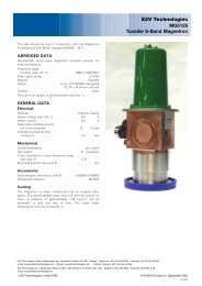
E2V Technologies MG5125P Tunable S-Band Magnetron
E2V Technologies MG5125P Tunable S-Band Magnetron
E2V Technologies MG5125P Tunable S-Band Magnetron

You also want an ePaper? Increase the reach of your titles
YUMPU automatically turns print PDFs into web optimized ePapers that Google loves.
MAXIMUM AND MINIMUM RATINGS<br />
(Absolute values)<br />
These ratings cannot necessarily be used simultaneously, and<br />
no individual rating should be exceeded.<br />
Min Max<br />
Magnetic field<br />
(see notes 5 and 7) . . . . . 110.0 157.5 mT<br />
1100 1575 gauss<br />
Heater voltage (see note 2) . . . . 8.0 10 V<br />
Heater starting current (peak) . . . – 20 A<br />
Anode voltage (peak) . . . . . . – 46 kV<br />
Anode current (peak) . . . . . 60 100 A<br />
Input power (mean) . . . . . . – 5.0 kW<br />
Pulse duration . . . . . . . . – 5.0 ms<br />
Rate of rise of voltage pulse<br />
(see note 8) . . . . . . . 80 120 kV/ms<br />
Outlet water temperature . . . . – 50 8C<br />
VSWR at output coupler<br />
(see note 1) . . . . . . . . – 1.5:1<br />
Pressurising of waveguide<br />
(see note 9) . . . . . . . . – 3.1 kg/cm 2 g<br />
TEST CONDITIONS AND LIMITS<br />
The magnetron is tested to comply with the following electrical<br />
specification.<br />
Test Conditions<br />
Magnetic field (see notes 5 and 7) . . . 155.0 + 2.5 mT<br />
1550 + 25 gauss<br />
Heater voltage (for test) . . . . . . . . 0 V<br />
Anode current (peak) . . . . . . . . 100 A<br />
Duty cycle (see note 10) . . . . . . . . 0.001<br />
Pulse duration . . . . . . . . . . . 5.0 ms<br />
VSWR at output coupler . . . . . . . 1.1:1<br />
Minimum rate of rise of<br />
voltage pulse (see note 8) . . . . . 120 kV/ms<br />
Limits<br />
Min Max<br />
Anode voltage (peak) . . . . . 40 46 kV<br />
Output power (mean)<br />
(see note 11) . . . . . . . . 2.0 – kW<br />
Frequency (see notes 12, 13 and 14):<br />
lower end of tuning range { . . . – 2993 MHz<br />
upper end of tuning range { . . 3002 – MHz<br />
RF bandwidth at 1 / 4 power . . . . – 1.0 MHz<br />
Frequency pulling (VSWR<br />
not less than 1.5:1) . . . . . – 6.0 MHz<br />
Stability (see note 15) . . . . . – 0.5 %<br />
Heater current . . . . . . . . . . . . see note 16<br />
{ Inlet water at 40 8C.<br />
LIFE TEST<br />
The quality of all production is monitored by the random<br />
selection of tubes which are then life-tested under typical<br />
operation conditions. If the tube is to be operated under<br />
conditions other than those specified herein, <strong>E2V</strong> <strong>Technologies</strong><br />
should be consulted to verify that the life of the magnetron will<br />
not be impaired.<br />
NOTES<br />
1. It is recommended that the magnetron should be isolated<br />
from the load by means of an isolator of approved design.<br />
Information on the characteristics of a suitable isolator may<br />
be obtained from <strong>E2V</strong> <strong>Technologies</strong>.<br />
2. With no anode input power.<br />
The heater voltage must be reduced within 5 seconds after<br />
the application of HT according to the schedule shown on<br />
page 4.<br />
The magnetron heater must be protected against arcing by<br />
the use of a minimum capacitance of 4000 pF shunted<br />
across the heater directly at the input terminals; in some<br />
cases a capacitance as high as 2 mF may be necessary<br />
depending on the equipment design. For further details see<br />
the <strong>Magnetron</strong> Preamble.<br />
3. The tuner mechanism is driven by means of three tapped<br />
holes in the tuner knob (see outline drawing) via a flexible<br />
drive. The torque required is 0.7 kg-cm minimum; the<br />
torque applied must not exceed 5.0 kg-cm.<br />
4. To minimise frequency deviation when the magnetron is<br />
rotated about a horizontal axis, this axis should be parallel<br />
to the axis of the tuner.<br />
5. The magnetron is designed for use with a separate<br />
permanent magnet or electromagnet. The north seeking<br />
pole of the magnet must be adjacent to the cathode<br />
terminal, marked C. The position of the magnet must be<br />
adjusted so that the axis of the field is in line with the axis<br />
of the anode and is at right angles to the H plane of the<br />
system waveguide. The user is invited to consult <strong>E2V</strong><br />
<strong>Technologies</strong> on the choice of magnets.<br />
6. The <strong>MG5125P</strong> can be used at lower power levels by<br />
reducing both the magnetic field (which controls the peak<br />
voltage) and the peak current (see graph); this is necessary<br />
for maintaining a good RF spectrum and constant<br />
impedance.<br />
7. Using a small Hall effect probe, the magnetic field<br />
measured at each pole face of the magnet must be within<br />
the following limits.<br />
(a) At the centre of the pole face and 37.287 mm from<br />
the surface, the field must be 155.0 + 2.5 mT (1550<br />
+ 25 gauss).<br />
(b) At four or more points equispaced on a circle of<br />
33 mm diameter concentric with the pole face and<br />
6.35 mm from its surface, including a point nearest<br />
the back limb of the magnet, the field must be as<br />
follows. At all points the field must be between 9.0<br />
and 27 mT (90 and 270 gauss) greater than the field<br />
measured at the centre of the pole face; the variation<br />
between the points must not exceed 13 mT<br />
(130 gauss).<br />
8. Defined as the steepest tangent to the leading edge of the<br />
voltage pulse above 80% amplitude. Any capacitance in<br />
the viewing system must not exceed 6.0 pF.<br />
9. At the maximum pressure of 3.1 kg/cm 2 (45 lb/in 2 ) gauge<br />
the maximum leakage will be such that with an enclosed<br />
volume of 1 litre the pressure will not drop by more than<br />
70 kPa in 7 days.<br />
<strong>MG5125P</strong>, page 2<br />
# <strong>E2V</strong> <strong>Technologies</strong>