E2V Technologies MG5125P Tunable S-Band Magnetron
E2V Technologies MG5125P Tunable S-Band Magnetron
E2V Technologies MG5125P Tunable S-Band Magnetron

Create successful ePaper yourself
Turn your PDF publications into a flip-book with our unique Google optimized e-Paper software.
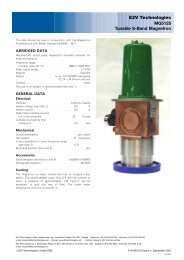
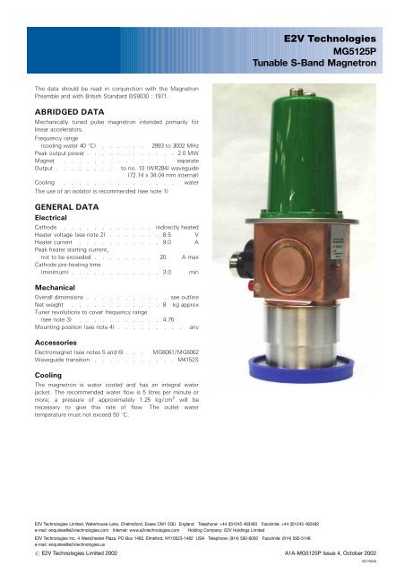
<strong>E2V</strong> <strong>Technologies</strong><br />
<strong>MG5125P</strong><br />
<strong>Tunable</strong> S-<strong>Band</strong> <strong>Magnetron</strong><br />
The data should be read in conjunction with the <strong>Magnetron</strong><br />
Preamble and with British Standard BS9030 : 1971.<br />
ABRIDGED DATA<br />
Mechanically tuned pulse magnetron intended primarily for<br />
linear accelerators.<br />
Frequency range<br />
(cooling water 40 8C) . . . . . . 2993 to 3002 MHz<br />
Peak output power . . . . . . . . . . . . 2.0 MW<br />
Magnet . . . . . . . . . . . . . . separate<br />
Output . . . . . . . . to no. 10 (WR284) waveguide<br />
(72.14 x 34.04 mm internal)<br />
Cooling . . . . . . . . . . . . . . . water<br />
The use of an isolator is recommended (see note 1)<br />
GENERAL DATA<br />
Electrical<br />
Cathode . . . . . . . . . . . . indirectly heated<br />
Heater voltage (see note 2) . . . . . . . 8.5 V<br />
Heater current . . . . . . . . . . . 9.0 A<br />
Peak heater starting current,<br />
not to be exceeded . . . . . . . . 20 A max<br />
Cathode pre-heating time<br />
(minimum) . . . . . . . . . . . . 3.0 min<br />
Mechanical<br />
Overall dimensions . . . . . . . . . . . see outline<br />
Net weight . . . . . . . . . . . . 8 kg approx<br />
Tuner revolutions to cover frequency range<br />
(see note 3) . . . . . . . . . . . 4.75<br />
Mounting position (see note 4) . . . . . . . . . any<br />
Accessories<br />
Electromagnet (see notes 5 and 6) . . . MG6061/MG6062<br />
Waveguide transition . . . . . . . . . . . M4152S<br />
Cooling<br />
The magnetron is water cooled and has an integral water<br />
jacket. The recommended water flow is 5 litres per minute or<br />
more; a pressure of approximately 1.25 kg/cm 2 will be<br />
necessary to give this rate of flow. The outlet water<br />
temperature must not exceed 50 8C.<br />
<strong>E2V</strong> <strong>Technologies</strong> Limited, Waterhouse Lane, Chelmsford, Essex CM1 2QU England Telephone: +44 (0)1245 493493 Facsimile: +44 (0)1245 492492<br />
e-mail: enquiries@e2vtechnologies.com Internet: www.e2vtechnologies.com Holding Company: <strong>E2V</strong> Holdings Limited<br />
<strong>E2V</strong> <strong>Technologies</strong> Inc. 4 Westchester Plaza, PO Box 1482, Elmsford, NY10523-1482 USA Telephone: (914) 592-6050 Facsimile: (914) 592-5148<br />
e-mail: enquiries@e2vtechnologies.us<br />
# <strong>E2V</strong> <strong>Technologies</strong> Limited 2002 A1A-<strong>MG5125P</strong> Issue 4, October 2002<br />
527/5645
MAXIMUM AND MINIMUM RATINGS<br />
(Absolute values)<br />
These ratings cannot necessarily be used simultaneously, and<br />
no individual rating should be exceeded.<br />
Min Max<br />
Magnetic field<br />
(see notes 5 and 7) . . . . . 110.0 157.5 mT<br />
1100 1575 gauss<br />
Heater voltage (see note 2) . . . . 8.0 10 V<br />
Heater starting current (peak) . . . – 20 A<br />
Anode voltage (peak) . . . . . . – 46 kV<br />
Anode current (peak) . . . . . 60 100 A<br />
Input power (mean) . . . . . . – 5.0 kW<br />
Pulse duration . . . . . . . . – 5.0 ms<br />
Rate of rise of voltage pulse<br />
(see note 8) . . . . . . . 80 120 kV/ms<br />
Outlet water temperature . . . . – 50 8C<br />
VSWR at output coupler<br />
(see note 1) . . . . . . . . – 1.5:1<br />
Pressurising of waveguide<br />
(see note 9) . . . . . . . . – 3.1 kg/cm 2 g<br />
TEST CONDITIONS AND LIMITS<br />
The magnetron is tested to comply with the following electrical<br />
specification.<br />
Test Conditions<br />
Magnetic field (see notes 5 and 7) . . . 155.0 + 2.5 mT<br />
1550 + 25 gauss<br />
Heater voltage (for test) . . . . . . . . 0 V<br />
Anode current (peak) . . . . . . . . 100 A<br />
Duty cycle (see note 10) . . . . . . . . 0.001<br />
Pulse duration . . . . . . . . . . . 5.0 ms<br />
VSWR at output coupler . . . . . . . 1.1:1<br />
Minimum rate of rise of<br />
voltage pulse (see note 8) . . . . . 120 kV/ms<br />
Limits<br />
Min Max<br />
Anode voltage (peak) . . . . . 40 46 kV<br />
Output power (mean)<br />
(see note 11) . . . . . . . . 2.0 – kW<br />
Frequency (see notes 12, 13 and 14):<br />
lower end of tuning range { . . . – 2993 MHz<br />
upper end of tuning range { . . 3002 – MHz<br />
RF bandwidth at 1 / 4 power . . . . – 1.0 MHz<br />
Frequency pulling (VSWR<br />
not less than 1.5:1) . . . . . – 6.0 MHz<br />
Stability (see note 15) . . . . . – 0.5 %<br />
Heater current . . . . . . . . . . . . see note 16<br />
{ Inlet water at 40 8C.<br />
LIFE TEST<br />
The quality of all production is monitored by the random<br />
selection of tubes which are then life-tested under typical<br />
operation conditions. If the tube is to be operated under<br />
conditions other than those specified herein, <strong>E2V</strong> <strong>Technologies</strong><br />
should be consulted to verify that the life of the magnetron will<br />
not be impaired.<br />
NOTES<br />
1. It is recommended that the magnetron should be isolated<br />
from the load by means of an isolator of approved design.<br />
Information on the characteristics of a suitable isolator may<br />
be obtained from <strong>E2V</strong> <strong>Technologies</strong>.<br />
2. With no anode input power.<br />
The heater voltage must be reduced within 5 seconds after<br />
the application of HT according to the schedule shown on<br />
page 4.<br />
The magnetron heater must be protected against arcing by<br />
the use of a minimum capacitance of 4000 pF shunted<br />
across the heater directly at the input terminals; in some<br />
cases a capacitance as high as 2 mF may be necessary<br />
depending on the equipment design. For further details see<br />
the <strong>Magnetron</strong> Preamble.<br />
3. The tuner mechanism is driven by means of three tapped<br />
holes in the tuner knob (see outline drawing) via a flexible<br />
drive. The torque required is 0.7 kg-cm minimum; the<br />
torque applied must not exceed 5.0 kg-cm.<br />
4. To minimise frequency deviation when the magnetron is<br />
rotated about a horizontal axis, this axis should be parallel<br />
to the axis of the tuner.<br />
5. The magnetron is designed for use with a separate<br />
permanent magnet or electromagnet. The north seeking<br />
pole of the magnet must be adjacent to the cathode<br />
terminal, marked C. The position of the magnet must be<br />
adjusted so that the axis of the field is in line with the axis<br />
of the anode and is at right angles to the H plane of the<br />
system waveguide. The user is invited to consult <strong>E2V</strong><br />
<strong>Technologies</strong> on the choice of magnets.<br />
6. The <strong>MG5125P</strong> can be used at lower power levels by<br />
reducing both the magnetic field (which controls the peak<br />
voltage) and the peak current (see graph); this is necessary<br />
for maintaining a good RF spectrum and constant<br />
impedance.<br />
7. Using a small Hall effect probe, the magnetic field<br />
measured at each pole face of the magnet must be within<br />
the following limits.<br />
(a) At the centre of the pole face and 37.287 mm from<br />
the surface, the field must be 155.0 + 2.5 mT (1550<br />
+ 25 gauss).<br />
(b) At four or more points equispaced on a circle of<br />
33 mm diameter concentric with the pole face and<br />
6.35 mm from its surface, including a point nearest<br />
the back limb of the magnet, the field must be as<br />
follows. At all points the field must be between 9.0<br />
and 27 mT (90 and 270 gauss) greater than the field<br />
measured at the centre of the pole face; the variation<br />
between the points must not exceed 13 mT<br />
(130 gauss).<br />
8. Defined as the steepest tangent to the leading edge of the<br />
voltage pulse above 80% amplitude. Any capacitance in<br />
the viewing system must not exceed 6.0 pF.<br />
9. At the maximum pressure of 3.1 kg/cm 2 (45 lb/in 2 ) gauge<br />
the maximum leakage will be such that with an enclosed<br />
volume of 1 litre the pressure will not drop by more than<br />
70 kPa in 7 days.<br />
<strong>MG5125P</strong>, page 2<br />
# <strong>E2V</strong> <strong>Technologies</strong>
10. The various parameters are related by the formula:<br />
Pi = i apk xv apk xDu<br />
where Pi = mean input power in watts<br />
i apk = peak anode current in amperes<br />
v apk = peak anode voltage in volts<br />
and Du = duty cycle.<br />
11. The maximum variation of mean output power when the<br />
magnetron is rotated through 3608 around any axis of the<br />
magnetron will not be greater than 6%.<br />
12. The frequency of the magnetron will vary after the<br />
application of anode voltage. Typically the frequency will<br />
be 0.5 MHz high 20 seconds after switching on HT and<br />
0.1 MHz high 5 minutes after switching on.<br />
13. With a water flow rate of 5.0 litres per minute. Other<br />
frequency ranges can be supplied on request.<br />
14. The maximum variation of frequency when the magnetron<br />
is rotated through 3608 around any axis of the magnetron<br />
will not be greater than 1.0 MHz.<br />
15. With the magnetron operating into a VSWR of 1.15:1.<br />
Pulses are defined as missing when the RF energy level is<br />
less than 70% of the normal energy level in a 0.5%<br />
frequency range. Missing pulses are expressed as a<br />
percentage of the number of input pulses applied during<br />
the period of observation after a period of 10 minutes<br />
operation.<br />
16. Measured with heater voltage of 8.5 V and no anode input<br />
power, the heater current limits are 8.0 A minimum, 10.0 A<br />
maximum.<br />
HEALTH AND SAFETY HAZARDS<br />
<strong>E2V</strong> <strong>Technologies</strong> magnetrons are safe to handle and operate,<br />
provided that the relevant precautions stated herein are<br />
observed. <strong>E2V</strong> <strong>Technologies</strong> does not accept responsibility for<br />
damage or injury resulting from the use of electronic devices it<br />
produces. Equipment manufacturers and users must ensure<br />
that adequate precautions are taken. Appropriate warning<br />
labels and notices must be provided on equipments<br />
incorporating <strong>E2V</strong> <strong>Technologies</strong> devices and in operating<br />
manuals.<br />
High Voltage<br />
Equipment must be designed so that personnel cannot come<br />
into contact with high voltage circuits. All high voltage circuits<br />
and terminals must be enclosed and fail-safe interlock switches<br />
must be fitted to disconnect the primary power supply and<br />
discharge all high voltage capacitors and other stored charges<br />
before allowing access. Interlock switches must not be<br />
bypassed to allow operation with access doors open.<br />
RF Radiation<br />
Personnel must not be exposed to excessive RF radiation. All<br />
RF connectors must be correctly fitted before operation so that<br />
no leakage of RF energy can occur and the RF output must be<br />
coupled efficiently to the load. It is particularly dangerous to<br />
look into open waveguide or coaxial feeders while the device is<br />
energised. Screening of the cathode sidearm of high power<br />
magnetrons may be necessary.<br />
X-Ray Radiation<br />
High voltage magnetrons emit a significant intensity of X-rays<br />
not only from the cathode sidearm but also from the output<br />
waveguide. These rays can constitute a health hazard unless<br />
adequate shielding for X-ray radiation is provided. This is a<br />
characteristic of all magnetrons and the X-rays emitted<br />
correspond to a voltage much higher than that of the anode.<br />
# <strong>E2V</strong> <strong>Technologies</strong> <strong>MG5125P</strong>, page 3
HEATER VOLTAGE REDUCTION SCHEDULE<br />
10<br />
6526B<br />
8<br />
6<br />
4<br />
HEATER VOLTAGE (V)<br />
2<br />
0<br />
0 1.0 2.0 3.0 4.0<br />
MEAN INPUT POWER (kW)<br />
<strong>MG5125P</strong>, page 4<br />
# <strong>E2V</strong> <strong>Technologies</strong>
RECOMMENDED PARAMETERS FOR VARIOUS POWER LEVELS<br />
MAGNETIC FIELD (mT)<br />
2.5<br />
110 120 130 140 150 155<br />
6961<br />
2.0<br />
1.5<br />
1.0<br />
NORMAL<br />
OPERATING<br />
CONDITIONS<br />
PEAK POWER (MW)<br />
0.5<br />
0<br />
25 ANODE VOLTAGE (V) 30 35 40 45<br />
60 ANODE CURRENT (A) 70 80 90 100<br />
73 FREQUENCY CHANGE (MHz) 72 71 7 1 / 2 0<br />
# <strong>E2V</strong> <strong>Technologies</strong> <strong>MG5125P</strong>, page 5
OUTLINE (All dimensions without limits are nominal)<br />
6828A<br />
1AB<br />
HOLE 1F<br />
ON AF PCD<br />
2 HOLES THREADED<br />
1 / 4 "-28 UNF-2B BY Z DEEP<br />
228<br />
228<br />
1X<br />
1H<br />
8 HOLES 1AA<br />
ON AF PCD<br />
SEE NOTE 3<br />
1AC<br />
HOLE 1Y<br />
ON AF PCD<br />
AE<br />
REFERENCE<br />
PLANE ‘A’<br />
REFERENCE<br />
PLANE ‘B’<br />
C<br />
SEE NOTE 1<br />
U<br />
V<br />
K<br />
J<br />
SEE NOTE 2<br />
T<br />
3 HOLES THREADED<br />
10-32 UNF-2B BY G DEEP<br />
EQUISPACED ON H PCD<br />
SEE NOTE 4<br />
A<br />
‘X’<br />
S<br />
Q<br />
L<br />
WATER JACKET<br />
CONNECTIONS<br />
THREADED 1 / 4 " BSP<br />
B<br />
C<br />
1N<br />
R<br />
1P<br />
F<br />
D<br />
1M<br />
SEE NOTE 5<br />
1E<br />
8 HOLES 1AG<br />
EQUISPACED ON AH PCD<br />
SEE NOTE 3<br />
HOLE THREADED<br />
M8 x 1.25-6H<br />
BY AJ DEEP<br />
Scrap View in Direction ‘X’<br />
<strong>MG5125P</strong>, page 6<br />
# <strong>E2V</strong> <strong>Technologies</strong>
Ref<br />
Millimetres<br />
A 370.0<br />
B 135.5<br />
C 89.0<br />
D 3.2<br />
E 104.9<br />
F 35.0<br />
G 6.5<br />
H 19.05<br />
J 73.82 + 0.20<br />
K 25.0<br />
L 12.5 + 0.5<br />
M 133.5<br />
N 94.85<br />
P 91.82<br />
Q 5.55<br />
R 31.4<br />
S 191.5<br />
T 55.96 + 0.16<br />
U 6.35 + 0.10<br />
V 107.0 + 0.3<br />
W 51.0<br />
X 38.0<br />
Y 6.40 + 0.05<br />
Z 6.0 max<br />
AA 8.0 + 0.1<br />
AB 152.25<br />
AC 19.0<br />
AD 8.00 + 0.05<br />
AE 107.0<br />
AF 139.7<br />
AG 6.4 + 0.1<br />
AH 120.65 + 0.13<br />
AJ 15.0 max<br />
Outline Notes<br />
1. This surface is marked with the letter ’C’ to indicate the<br />
cathode terminal.<br />
2. The magnetron will fit between magnet poles 76.45 mm<br />
diameter and 75.44 mm apart.<br />
3. Positional tolerance of holes 0.15 mm diameter.<br />
4. Positional tolerance of holes 0.05 mm diameter.<br />
5. Positional tolerance of flange 1.5 mm diameter with respect<br />
to reference planes A and B.<br />
Whilst <strong>E2V</strong> <strong>Technologies</strong> has taken care to ensure the accuracy of the information contained herein it accepts no responsibility for the consequences of any use<br />
thereof and also reserves the right to change the specification of goods without notice. <strong>E2V</strong> <strong>Technologies</strong> accepts no liability beyond that set out in its standard<br />
conditions of sale in respect of infringement of third party patents arising from the use of tubes or other devices in accordance with information contained herein.<br />
# <strong>E2V</strong> <strong>Technologies</strong> Printed in England<br />
<strong>MG5125P</strong>, page 7