
Create successful ePaper yourself
Turn your PDF publications into a flip-book with our unique Google optimized e-Paper software.
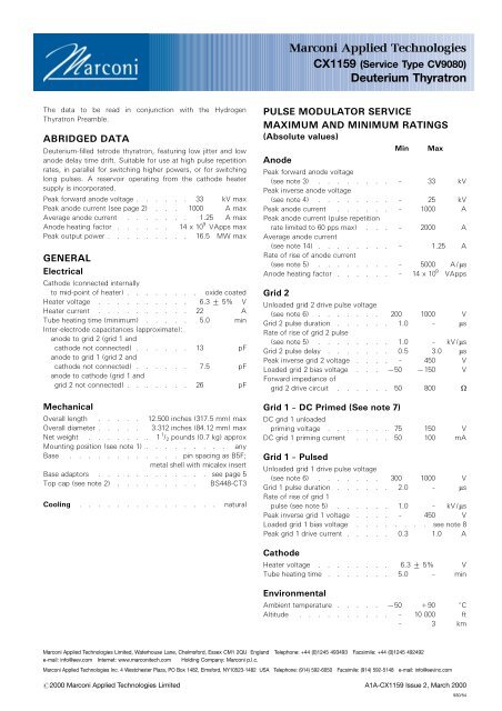
CHARACTERISTICSMin Typical MaxCritical DC anode voltage forconduction (see note 9) . . . ± 0.5 2.0 kVAnode delay time(see notes 9 and 10) . . . . ± 0.15 0.25 msAnode delay time drift(see notes 9, 11 and 12) . . . ± 20 50 nsTime jitter (see notes 9 and 12) . ± 1.0 5.0 nsRecovery time . . . . . . . . see note 13 and curvesHeater current (at 6.3 V) . . 18 22 25 ARATINGS FOR SINGLE SHOT ORCROWBAR SERVICE(See note 7)DC forward anode voltage . . . . . . . 30 kV maxPeak anode current . . . . . . . 15 000 A maxProduct of peak current and pulse duration . 0.6 A.s maxRepetition frequency . . . . . . . 1 pulse per 10 s maxNOTES1. Clamping is only permissible by the base.2. A large area anode connector, Marconi AppliedTechnologies type MA360, is recommended.3. The maximum permissible peak forward voltage forinstantaneous starting is 20 kV and there must be noovershoot.4. The peak inverse voltage must not exceed 25 kV for thefirst 25 ms after the anode pulse.5. This rate of rise refers to that part of the leading edge ofthe pulse between 25% and 75% of the pulse amplitude.6. Measured with respect to cathode. In certain cases themaximum drive pulse voltage may be exceeded withoutdamage to the tube; a maximum value of 2.5 kV is thenrecommended. When grid 1 is pulse driven, the last 0.25 msof the top of the grid 1 pulse must overlap thecorresponding first 0.25 ms of the top of the delayed grid2 pulse.7. When DC priming is used on grid 1, a negative bias of 100to 200 V must be applied to grid 2 to ensure anode voltagehold-off. DC priming is recommended for crowbar service.8. DC negative bias voltages must not be applied to grid 1.When grid 1 is pulse driven, the potential of grid 1 mayvary between 710 and +5 V with respect to cathodepotential during the period between the completion ofrecovery and the commencement of the succeeding gridpulse.9. Typical figures are obtained on test using conditions ofminimum grid drive. Improved performance can beexpected by increasing the grid drive.10. The time interval between the instant at which the risingunloaded grid 2 pulse reaches 25% of its pulse amplitudeand the instant when anode conduction takes place.11. The drift in delay time over a period from 10 seconds to 10minutes after reaching full voltage.12. For equipment where jitter and anode delay time drift arenot important, the tube may be triggered by applying asingle pulse to grid 2 and connecting grid 1 to grid 2 via a1000 pF capacitor shunted by a 0.1 MO resistor. Thesecomponents are incorporated in adaptor assemblies MA92and MA179 (see below).13. The recovery characteristics are controlled on a samplingbasis.14. For inverter type applications where the peak current doesnot exceed 50 A, the maximum average anode currentmay be increased to 2.5 A; Marconi Applied Technologiesshould be consulted.HEALTH AND SAFETY HAZARDSMarconi Applied Technologies hydrogen thyratrons are safe tohandle and operate, provided that the relevant precautionsstated herein are observed. Marconi Applied Technologies doesnot accept responsibility for damage or injury resulting from theuse of electronic devices it produces. Equipment manufacturersand users must ensure that adequate precautions are taken.Appropriate warning labels and notices must be provided onequipments incorporating Marconi Applied Technologiesdevices and in operating manuals.High VoltageEquipment must be designed so that personnel cannot comeinto contact with high voltage circuits. All high voltage circuitsand terminals must be enclosed and fail-safe interlock switchesmust be fitted to disconnect the primary power supply anddischarge all high voltage capacitors and other stored chargesbefore allowing access. Interlock switches must not bebypassed to allow operation with access doors open.X-Ray RadiationAll high voltage devices produce X-rays during operation andmay require shielding. The X-ray radiation from hydrogenthyratrons is usually reduced to a safe level by enclosing theequipment or shielding the thyratron with at least1 / 16 -inch(1.6 mm) thick steel panels.Users and equipment manufacturers must check the radiationlevel under their maximum operating conditions.ADAPTOR ASSEMBLIESIn addition to standard top cap connectors and base sockets, anumber of adaptor assemblies are available from MarconiApplied Technologies.MA91A five-contact socket fitted with flexible leads and terminaltags, and mounted on an insulating base plate. It provides aconversion from base to flange type mounting.MA92Similar to MA91 but incorporates an RC network and isdesigned for use with CX1159 where a single pulse drive andflying lead connections are required.MA179A five-contact socket with flexible leads and terminal tags,mounted on an insulating base plate; it is fitted with a baseclamp. It incorporates an RC network and is designed for usewith CX1159 where a single pulse drive and flying leadconnections are required.Further information is contained in the leaflet 'Accessories forHydrogen Thyratrons'.CX1159, page 2#2000 Marconi Applied Technologies
MAXIMUM RECOVERY CHARACTERISTICS902870BPEAK ANODE CURRENT 1000 ARE-APPLIED ANODE VOLTAGE 1 kV80GRID 2 VOLTAGE 0 V706050712.540725MAXIMUM RECOVERY TIME (ms)30201075071000100 500 1000 5000 10 000 50 000GRID 2 RECOVERY IMPEDANCE (O)#2000 Marconi Applied Technologies CX1159, page 3
OUTLINE(All dimensions without limits are nominal)2871C1EADRef Inches MillimetresA 12.000 + 0.500 304.8 + 12.7B 3.312 max 84.12 maxC 8.500 + 0.500 215.9 + 12.7D 0.500 min 12.7 minE 0.566 + 0.007 14.38 + 0.18F 0.187 + 0.003 4.750 + 0.076G 1.250 31.75H 1.937 49.2J 3.062 + 0.062 77.77 + 1.57K 0.770 max 19.56 maxL 0.073 max 1.85 maxM 0.575 min 14.6 minN 0.260 max 6.6 maxC1BBASE PIN SPACINGAS B5F. METAL SHELLWITH MICALEX INSERTMillimetre dimensions have been derived from inches.1JHKM1NL5 PINS 1FON G PCD453083213084316Ak, h ctg 23aCap2 4g 1PinElement1 Heater2 Cathode, connected internallyto heater mid-point3 Grid 24 Grid 15 HeaterTop cap Anodeh k15h kReservoirs(internal)Whilst Marconi Applied Technologies has taken care to ensure the accuracy of the information contained herein it accepts no responsibility for the consequences of anyuse thereof and also reserves the right to change the specification of goods without notice. Marconi Applied Technologies accepts no liability beyond that set out in itsstandard conditions of sale in respect of infringement of third party patents arising from the use of tubes or other devices in accordance with information contained herein.CX1159, page 4Printed in England#2000 Marconi Applied Technologies