System Sensor Ionization Smoke Detector - Gamewell-FCI
System Sensor Ionization Smoke Detector - Gamewell-FCI
System Sensor Ionization Smoke Detector - Gamewell-FCI

Create successful ePaper yourself
Turn your PDF publications into a flip-book with our unique Google optimized e-Paper software.
R<br />
1415<br />
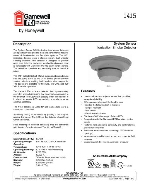
Description<br />
The <strong>System</strong> <strong>Sensor</strong> 1451 ionization type smoke detectors<br />
are specifically designed to meet the performance requirements<br />
of fire detection and fire alarm systems. The 1451<br />
ionization detector uses a state-of-the-art, dual unipolar<br />
sensing chamber. The detector is designed to provide<br />
open area detection and when installed in a two-wire base<br />
is compatible with <strong>Gamewell</strong>-<strong>FCI</strong> fire alarm control panels.<br />
The detectors operation and sensitivity can be tested in<br />
place.<br />
The 1451 detector is built of plug-in construction and plugs<br />
into the same base as the 2451 Series photoelectronic<br />
smoke detectors, making both models interchangeable.<br />
The bases are available for two-wire, four-wire, and 120<br />
VAC four wire operation.<br />
Two visible LEDs on each detector flash approximately<br />
every ten seconds indicating that power is being applied to<br />
the detector. The LEDs light steadily when the detector is<br />
in alarm. A remote LED annunciator is available as an<br />
optional accessory.<br />
The 1451 detector is Listed for use inside ducts up to a<br />
velocity of 1,200 FPM.<br />
Sensitivity testing is performed by placing a test magnet<br />
against the cover. The LED on the detector should light<br />
within 5 seconds.<br />
Field metering of detector sensitivity may be performed<br />
with the aid of a voltmeter and Test Kit, MOD 400R.<br />
Specifications<br />
Nominal Sensitivity: 1.5 %/ft<br />
Operating Voltage: 8.5 - 35 VDC (24 VDC nominal)<br />
Operating<br />
Temperature: 32° to 120° F (0° to 49° C)<br />
Operating Humidity: 10 % - 93 % relative humidity<br />
Air Velocity: 1,200 FPM<br />
Altitude:<br />
10,000 ft.<br />
Construction: Off-white flame retardant plastic<br />
Diameter:<br />
6.2 inches (15.7 cm)<br />
Height:<br />
3.2 inches (8.1 cm)<br />
Weight: 0.5 lb (277 g)<br />
Features<br />
<strong>System</strong> <strong>Sensor</strong><br />
<strong>Ionization</strong> <strong>Smoke</strong> <strong>Detector</strong><br />
1415<br />
• Uses a unique dual unipolar sensor that provides<br />
exceptional stability<br />
• Offers an easy plug-in of the head to base<br />
• Provides the following built-in features:<br />
- Tamper-resistant<br />
- Test switch<br />
- Visual alarm indicators<br />
• Displays a 360° view angle of alarm LEDs<br />
• Compatible with the <strong>Gamewell</strong>-<strong>FCI</strong> fire alarm control<br />
panels<br />
• Performs field adjustable sensitivity and field metering<br />
of detector sensitivity<br />
• Furnishes insect-resistant screening (.020"/.508 mm<br />
openings)<br />
• Includes a removable insect screen and cover for field<br />
cleaning<br />
• Sealed against dirt, insects, and back pressure<br />
SIGNALING<br />
An ISO 9000-2000 Company<br />
FM<br />
APPROVED<br />
MEA<br />
Approved<br />
C<br />
U L<br />
US LISTED<br />
GAMEWELL-<strong>FCI</strong><br />
12 Clintonville Road, Northford, CT 06472-1610 USA • Tel: (203) 484-7161 • Fax: (203) 484-7118<br />
Specifications are for information only, are not intended for installation purposes, and are subject to change without notice. No responsibility is assumed by <strong>Gamewell</strong>-<strong>FCI</strong> for their use.<br />
©2009 by Honeywell International Inc. All rights reserved. www.gamewell-fci.com 9020-0584 Rev. C page 1 of 2
Mounting<br />
• On a 4 inch square box with or without plaster ring or<br />
supplied adapter. Minimum depth 1.5 inches<br />
• On a 3.5 or 4 inch octagonal box. Minimum depth 1.5<br />
inches<br />
• On a single gang box. Min. depth 1.5 inches<br />
Installation<br />
Place the detector into the detector base. Turn the detector<br />
clockwise until the detector locks into place.<br />
To use the tamper-proof feature, break the smaller tab on<br />
the scribed line in the tamper proof tab located on the<br />
detector mounting bracket. Install the detector. To remove<br />
the detector from the base when using the tamper-proof<br />
feature, insert the blade of a small screwdriver into the<br />
hole on the side of the base and push the plastic lever<br />
away from the detector head. This will allow the detector to<br />
be rotated counterclockwise for removal.<br />
Note: The decorative ring must be removed in order to<br />
remove the head when using the tamper-proof feature.<br />
The tamper-proof feature may be defeated permanently by<br />
breaking the plastic lever off the base<br />
Note: The number of two-wire smoke detectors which can<br />
be accommodated per zone varies with different control<br />
panels. Consult the control panel instruction manual to<br />
determine the capacity.<br />
Refer to NFPA 72, Chapter 5-3, “<strong>Smoke</strong> Sensing Fire<br />
<strong>Detector</strong>s” for spacing, location of detectors and other<br />
guidelines.<br />
Testing<br />
<strong>Detector</strong>s may be tested in the following ways:<br />
• Place a test magnet against the cover opposite the test<br />
module socket. (See illustration). The detector should<br />
go into alarm within 5 seconds.<br />
• Field metering of detector sensitivity may be performed<br />
with the aid of a voltmeter and Test Kit MOD 400R. For<br />
the complete procedure, refer to the Installation and<br />
Maintenance Instructions furnished with each detector.<br />
Maintenance<br />
Cleaning programs should be adapted to the individual<br />
environment. We recommend at least, an annual cleaning<br />
of the unit. The detector screen and cover assembly can<br />
be removed, revealing the sensing chamber. A vacuum<br />
cleaner can be used to remove dust from the screen,<br />
cover and sensing chamber. For the complete procedure,<br />
refer to the Installation and Maintenance Instructions furnished<br />
with each detector.<br />
RECESSED<br />
TEST SWITCH<br />
LED<br />
TAMPER<br />
SLOT<br />
TEST MODULE<br />
SOCKET<br />
Views Show Position of Test Magnet<br />
Figure 1<br />
WARNING: To prevent detector contamination during construction,<br />
smoke detectors must be protected from dust<br />
and contamination until the area is clean and dust free. see<br />
NFPA 72 -5-3.7.1.3.<br />
Ordering Information<br />
LOCK PRONG<br />
PUSH RECESSED<br />
SWITCH WITH A 0.1"<br />
MAX. DIAMETER<br />
TOOL<br />
REMOVABLE<br />
COVER FOR<br />
CLEANING<br />
REMOVABLE<br />
SCREEN<br />
Part Number Description<br />
1451 <strong>Ionization</strong> <strong>Detector</strong><br />
Alarm Current ‡<br />
B401B Base, two-wire<br />
Supervisory<br />
Current 00012 A<br />
Alarm Current ‡<br />
B402B Base, four-wire, 24 VDC operation<br />
Supervisory .00012 A<br />
Current .036 A<br />
Contacts Form A, C*<br />
B404B Base, four-wire, 120 VAC operation<br />
Contacts Form A, C* & Supvervisory<br />
RA-400 Remote alarm indicator<br />
Alarm Current .007 A<br />
PAM-1 End-of-line relay, 24 VDC<br />
Alarm Current .015 A<br />
Contacts Form B Test kit<br />
*Resistive load<br />
(Contact<br />
Ratings):<br />
Form A - 2.0 A @ 30 VAC/DC<br />
Form C - 2.0 A @ 30 VAC/DC, 1.0 A<br />
@ 120 VAC<br />
‡Note: Alarm current of detector is limited by control panel<br />
initiating device circuit.<br />
GAMEWELL-<strong>FCI</strong><br />
12 Clintonville Road, Northford, CT 06472-1610 USA • Tel: (203) 484-7161 • Fax: (203) 484-7118<br />
9020-0584 Rev. C page 2 of 2 www.gamewell-fci.com