High Performance Air-Conditioning - ACS Shop & Service
High Performance Air-Conditioning - ACS Shop & Service
High Performance Air-Conditioning - ACS Shop & Service

Create successful ePaper yourself
Turn your PDF publications into a flip-book with our unique Google optimized e-Paper software.
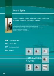
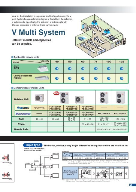
Ideal for the installation in large area and L-shaped rooms, the V<br />
Multi System has an extensive degree of flexibility in the selection<br />
of indoor units. Specifically, the selection of indoor units with<br />
different capacities in different types can be made.<br />
V Multi System<br />
Different models and capacities<br />
can be selected.<br />
Applicable indoor units<br />
Model<br />
4way<br />
Capacity<br />
Ceiling Suspended<br />
Combination of indoor units<br />
NEW<br />
FDC71VNX<br />
FDC100VNX<br />
FDC100VSX<br />
FDC125VNX<br />
FDC125VSX<br />
FDC140VNX<br />
FDC140VSX<br />
Micro Inverter<br />
FDC100VNV<br />
FDC100VSV<br />
40 + 40 50 + 50<br />
FDC125VNV<br />
FDC125VSV<br />
60 + 60<br />
50 + 71<br />
FDC140VNV<br />
FDC140VSV<br />
71 + 71<br />
FDC200VSV<br />
100 + 100<br />
71 + 125<br />
50 + 50 + 50 71 + 71 + 71<br />
FDC250VSV<br />
125 + 125<br />
60 + 60 + 125<br />
71 + 71 + 100<br />
50+50+50+50 60+60+60+60<br />
Floor<br />
Floor<br />
Triple type<br />
The indoor_outdoor piping length differences among indoor units are less than 3m.<br />
Model FDC140VNV/VSV<br />
[Branch pipe set : DIS-TA1]<br />
Outdoor unit<br />
Liquid line<br />
Gas line<br />
L<br />
1<br />
2<br />
3<br />
3<br />
3<br />
Indoor unit<br />
(Example)<br />
Item<br />
Indoor unit<br />
Liquid pipe<br />
Gas pipe<br />
Model combinations Main pipe Branch pipe Main pipe Branch pipe<br />
FDC140 50+50+50 ø9.52Xt0.8 ø9.52Xt0.8 ø15.88Xt1.0 ø12.7Xt0.8<br />
Notes (1) The reducer 3 supplied with the branch piping set should be used in order to reduce the liquid piping size<br />
from ø9.52mm to ø6.35mm at indoor unit side (flare connection). Accordingly be sure to select the liquid piping<br />
size ø9.52mm from branch to indoor unit.<br />
Chart of shapes of<br />
branch piping parts<br />
(DIS-TA1)<br />
ID15.88<br />
Gas pipe<br />
100 80 80<br />
10<br />
300<br />
ID12.7x3<br />
10<br />
100<br />
Symbol<br />
1<br />
8<br />
ID9.52<br />
Liquid pipe Symbol Reducer Symbol<br />
237<br />
100<br />
14°<br />
ID9.52x3<br />
Notes (1) Symbol 1 to 3 in the drawing shows the symbols of branch piping parts in the chart respectively.<br />
(2) Branch piping should always be arranged to have level or perpendicular position.<br />
8<br />
30 30<br />
2<br />
ID9.52<br />
8<br />
105<br />
50<br />
ø6.35<br />
flared<br />
nut<br />
3<br />
25