Underfill Flow as Viscous Flow Between Parallel Plates Driven - Profile
Underfill Flow as Viscous Flow Between Parallel Plates Driven - Profile
Underfill Flow as Viscous Flow Between Parallel Plates Driven - Profile

Create successful ePaper yourself
Turn your PDF publications into a flip-book with our unique Google optimized e-Paper software.
IEEE TRANSACTIONS ON COMPONENTS, PACKAGING, AND MANUFACTURING TECHNOLOGY-PART C, VOL. 19, NO. 2, APRIL 1996 133<br />
<strong>Underfill</strong> <strong>Flow</strong> <strong>as</strong> <strong>Viscous</strong> <strong>Flow</strong> <strong>Between</strong><br />
<strong>Parallel</strong> <strong>Plates</strong> <strong>Driven</strong> by Capillary Action<br />
Matthew K. Schwiebert and William H. Leong<br />
Abstruct- Epoxy underfill is often required to enhance the<br />
reliability of flip-chip interconnects, This study evaluates the flow<br />
of typical epoxy underfill materials between parallel plates driven<br />
by capillary action. An exact model w<strong>as</strong> developed to understand<br />
the functional relationship between flow distance, flow time,<br />
separation distance, surface tension, and viscosity for qu<strong>as</strong>isteady<br />
laminar flow between parallel plates. The model w<strong>as</strong> verified<br />
experimentally with a typical underfill material. The me<strong>as</strong>ured<br />
values of flow distance agreed well with the exact model. A<br />
new material parameter, the coefficient of planar penetrance, is<br />
introduced. This parameter me<strong>as</strong>ures the penetrating power of<br />
a liquid between parallel plates driven by capillary action. The<br />
effectiveness of gravity and vacuum <strong>as</strong> flow rate enhancements<br />
is explored.<br />
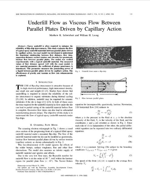
Fig. 1. <strong>Underfill</strong> front under a flip-chip.<br />
I. INTRODUCTION<br />
HE USE of flip-chip interconnect is attractive because of<br />
T its high electrical performance, high interconnect density,<br />
and small size and weight [I]-[4]. Studies have shown that<br />
underfilling is required to ensure the reliability of the solder<br />
interconnect to organic substrates during thermal cycling<br />
[5]-[lo]. In addition, underfill may be required for ceramic<br />
substrates if the die is large [lll-[15]. In both of these c<strong>as</strong>es<br />
the time required for the underfill material to flow under the die<br />
can lead to partial curing of the underfill material before flow<br />
is complete. Excessive flow times can also lead to substantial<br />
manufacturing process delays. The objective of this study is to<br />
understand the flow of typical epoxy underfill materials under<br />
flip-chips.<br />
11. UNDERFILL FLOW MODEL<br />
The scanning electron micrograph in Fig. 1 shows a cured<br />
cross section of the progressing front of a typical filled epoxy<br />
underfill material under a mounted flip-chip. The flow of the<br />
underfill material under the die can be modeled <strong>as</strong> qu<strong>as</strong>isteady,<br />
laminar flow between parallel plates driven by surface tension<br />
(capillary action), <strong>as</strong> shown schematically in Fig. 2.<br />
This two-dimensional (2-D) model ignores the effects of<br />
the solder bumps, surface roughness, flux and other flow<br />
obstructions. The model also <strong>as</strong>sumes an infinite supply of<br />
underfill material and ignores end effects.<br />
Due to the very low flow rates, the Reynolds number for<br />
underfill flow is on the order of lop5, well within the laminar<br />
region for parallel plate flow (< 10’)). The Navier-Stokes<br />
Manuscript revised March 26, 1996.<br />
The authors are with the Electronic Assembly Development Center,<br />
Hewlett-Packard Company, Palo Alto, CA 94304-1126 USA.<br />
Publisher Item Identifier S 1083-4400(96)04902-9.<br />
Fig. 2.<br />
I- L<br />
<strong>Flow</strong> between parallel plates<br />
equation for incompressible, qu<strong>as</strong>isteady, laminar, Newtonian,<br />
2-D horizontal flow [16] reduces to<br />
where p is the pressure in the fluid at x, p is the absolute<br />
viscosity of the fluid, V, is the velocity of the fluid, and the<br />
coordinates x and y are oriented <strong>as</strong> shown in Fig. 2. Since<br />
each side of (1) is independent of the other, the partial differential<br />
equation can be separated into two ordinary differential<br />
equations<br />
d2<br />
p-V, = -p<br />
dY2<br />
where / is a constant. Solving (2b) subject to the boundary<br />
conditions V&=tLp = VZly=--h/2 = 0 gives<br />
The speed of the front (dL/dt) is equal to the average flow<br />
velocity V,<br />
dL<br />
dt<br />
V, dy .<br />
(3)<br />
(4)<br />
1083-4400/96$05.00 0 1996 IEEE
134 SEEE TRANSACTSONS ON COMPONENTS, PACKAGING. AND MANUFACTURING TECHNOLOGY-PART C, VOL. 19, NO. 2, APRIL 1996<br />
Substituting (3) into (4), integrating and solving for /3 gives<br />
12p dL<br />
pr- - (5)<br />
h2 (dt).<br />
By substituting (5) into (2a), the head loss (@/ax) can be<br />
expressed by the partial differential equation<br />
ap - 12p dL<br />
---&E) dx<br />
The Laplace-Young equation of capillarity states that the<br />
pressure drop across the free surface of a liquid-vapor interface,<br />
from the concave side to the convex side, is inversely<br />
proportional to the radius of curvature of the free surface [17],<br />
[18]. The radius of curvature of the free surface for the two<br />
dimensional c<strong>as</strong>e can be shown to be h/2cosO, where Q is<br />
the wetting angle that the underfill makes with the planes (see<br />
Fig. 2). From the Laplace-Young equation, the pressure drop<br />
across the free surface (Ap) can be expressed <strong>as</strong><br />
27 cos e<br />
Ap = ~<br />
(7)<br />
h<br />
where y is the surface tension of the liquid-vapor interface.<br />
Since dL/dt is independent of x and dpldx is independent of<br />
t, (6) can be separated into two ordinary differential equations<br />
*=r<br />
dx<br />
where r is a constant. Since the boundary condition at x = L<br />
is on the convex side of the interface plx=~<br />
= -Ap. Solving<br />
(8a) subject to the boundary conditions<br />
gives<br />
2y COS 0<br />
Pjx=o = 0, P l d = -~ h<br />
27 cos 6'<br />
r=-- (9)<br />
hL '<br />
Substituting (9) into (8b) and solving subject to the conditions<br />
Llt=o = 0, Llt=t, = Lf<br />
where tf is the flow time and Lf is the flow distance gives<br />
12& - 2ycos6'<br />
~- ~<br />
-<br />
h2 2<br />
h tf.<br />
Rearranging (10) and dropping subscripts gives<br />
hty cos 0<br />
Alternatively, solving (1 1) for the flow time gives<br />
3pL2<br />
t=- hy cos 6' '<br />
The flow time for viscous flow between parallel plates driven<br />
by capillary action is inversely proportional to the surface<br />
tension, separation distance, and the cosine of the wetting<br />
angle, and directly proportional to the viscosity and the square<br />
of the flow distance.<br />
The quantity (y COS 6')/2p me<strong>as</strong>ures the penetrating power<br />
of a liquid into a horizontal capillary tube, and w<strong>as</strong> defined<br />
by W<strong>as</strong>hburn [19] <strong>as</strong> the coeficient of penetrance. Since<br />
underfill flow under flip-chips more closely resembles flow<br />
between parallel plates, we can define an analogous term <strong>as</strong><br />
the coejjicient of planar penetrance (a), <strong>as</strong><br />
(y cos 6')/3p. (13)<br />
This parameter me<strong>as</strong>ures the penetrating power of a liquid<br />
into a gap between parallel plates, and h<strong>as</strong> units of velocity.<br />
Substituting the coefficient of planar penetrance into (1 1) and<br />
(12) gives<br />
and<br />
L=V%% (14)<br />
t = L2/@h. (15)<br />
In practice, most underfill materials wet the parallel plate<br />
surfaces, resulting in near zero wetting angles <strong>as</strong> can be seen<br />
in Fig. 1. In this c<strong>as</strong>e, cos 6' M 1, leaving y/3pL. Assuming ideal<br />
wetting, the penetrating power of a liquid into a gap between<br />
parallel plates is characterized by 113 of the ratio of the surface<br />
tension of the liquid to its viscosity. Since this parameter may<br />
be strongly related to the temperature of the underfill material,<br />
it should be me<strong>as</strong>ured and specified at the recommendedflow<br />
temperature, which is often higher than room temperature.<br />
111. EMPIRICAL VERIFICATION OF THE MODEL<br />
The exact relationship developed in (14) w<strong>as</strong> verified experimentally.<br />
The surface tension and viscosity of a typical filled<br />
epoxy underfill material were me<strong>as</strong>ured and used to calculate<br />
the coefficient of planar penetrance (a). This value w<strong>as</strong> then<br />
substituted into (14) to calculate the flow distance (L). The<br />
actual flow distance of the underfill material w<strong>as</strong> determined<br />
by Bowing the underfill between parallel plates. The model<br />
w<strong>as</strong> verified by comparing the flow distance predicted by (14)<br />
to the actual flow distance from the parallel plate flow test.<br />
The viscosity of the underfill material w<strong>as</strong> characterized<br />
with a temperature controlled rheometer. A 4.0 cm parallel<br />
plate with a gap of 175 pm w<strong>as</strong> used. The viscosity w<strong>as</strong> a<br />
very strong function of temperature. The viscosity w<strong>as</strong> nearly<br />
constant over a shear stress range of 20 to 100 Pa, indicating<br />
highly Newtonian behavior. A viscosity of 0.775 kglms w<strong>as</strong><br />
me<strong>as</strong>ured at a temperature of 80"C, and a shear stress of 100<br />
Pa.<br />
The surface tension of the underfill material w<strong>as</strong> determined<br />
experimentally by me<strong>as</strong>uring the capillary rise in 0.50 mm<br />
diameter gl<strong>as</strong>s capillary tubes at 80°C. Using a receding<br />
meniscus, a value of 0.036 N/m w<strong>as</strong> me<strong>as</strong>ured. Using a<br />
progressing meniscus, a value of 0.015 N/m w<strong>as</strong> me<strong>as</strong>ured.<br />
Since underfill flow involves a progressing meniscus, the value<br />
of 0.015 Nlm from the progressing meniscus w<strong>as</strong> substituted<br />
for the ycos6' term in the calculation of the coefficient of<br />
planar penetrance. The use of this value <strong>as</strong>sumes that the<br />
surface of the capillary tube is similar <strong>as</strong> the surfaces of the<br />
parallel plates.
SCHWIEBERT AND LEONG: UNDERFILL FLOW AS VISCOUS FLOW BETWEEN PARALLEL PLATES DRIVEN BY CAPILLARY ACTION 135<br />
50<br />
40<br />
30<br />
20<br />
10<br />
<strong>Underfill</strong> Reservoir<br />
Top View<br />
Gl<strong>as</strong>s Plate<br />
Section A-A<br />
Fig. 3. <strong>Parallel</strong> plate flow test setup.<br />
<strong>Underfill</strong> <strong>Flow</strong><br />
Shim<br />
0<br />
50<br />
(1<br />
40<br />
Y<br />
Ji<br />
30<br />
0<br />
E<br />
fa<br />
t 20<br />
6<br />
p 10<br />
The coefficient of planar penetrance of the underfill at 80°C<br />
w<strong>as</strong> calculated from the me<strong>as</strong>ured values of viscosity and<br />
surface tension to be ch. z (ycosO)/3p M 0.0064 ds.<br />
The actual flow distance w<strong>as</strong> determined with a simple<br />
parallel plate flow experiment. The experimental setup is<br />
shown in Fig. 3. A 125-pm thick piece of shim stock w<strong>as</strong><br />
placed under one edge of a gl<strong>as</strong>s-ceramic sandwich. The slight<br />
inclination of the gl<strong>as</strong>s with respect to the ceramic resulted in<br />
a continuously varied separation distance from zero to 125<br />
pm. The gl<strong>as</strong>s-ceramic sandwich w<strong>as</strong> placed on a temperature<br />
controlled heating plate to maintain the temperature of the<br />
underfill at 80°C during the flow. At t = 0, the underfill w<strong>as</strong><br />
dispensed into a reservoir along one of the inclined edges. The<br />
flow pattern w<strong>as</strong> then videotaped through the gl<strong>as</strong>s plate, along<br />
with a stop-watch which recorded the flow time.<br />
The solid white lines in Fig. 4 are calculated from (14),<br />
evaluated at Q, = 0.0064 d s . The black are<strong>as</strong> of the plots<br />
are the actual extent of the underfill flow <strong>as</strong> a function<br />
of separation distance and flow time <strong>as</strong> captured from the<br />
videotaped flow experiment. The trends <strong>as</strong> well <strong>as</strong> the absolute<br />
values of the actual underfill flow agree remarkably well with<br />
the model at separation distance of approximately 60 pm<br />
or greater. The discrepancy of the actual flow distance at a<br />
separation distance below 60 pm is likely due to the fact<br />
that the spherical filler particles, which were up to 35 pm<br />
in diameter, could not flow freely through these small gaps.<br />
The rough profile of the underfill fronts is likely a result of<br />
the fingering effect described by German [20]. Fingering can<br />
be caused by localized variations in the filler packing density.<br />
Finally, due to the extent of the flow at t = 1800 s, some of<br />
the underfill may have displaced laterally (from right to left)<br />
causing some distortion in the actual flow data.<br />
Both the model and the data also show that the flow rate<br />
decre<strong>as</strong>es <strong>as</strong> the front progresses. Qualitatively, this can be<br />
0<br />
50<br />
40<br />
30<br />
20<br />
70<br />
0 0 20 40 60 80 100 120<br />
Separation Distance, h, [ pm]<br />
Fig. 4. Experimental results versus model<br />
explained by the fact that the capillary force driving the flow<br />
remains constant, while the amount of material being pulled<br />
along, dissipating energy through viscous shearing, incre<strong>as</strong>es.<br />
The model and the data also agree that the flow rate is slower<br />
for small values of separation distance. Qualitatively, more<br />
shearing of the underfill is required to flow through the smaller<br />
gaps, dissipating more energy, slowing the flow.<br />
Iv. EFFECTS OF GRAVITY AND VACUUh4 ON FLOW RATE<br />
With this b<strong>as</strong>ic understanding of the parameters affecting<br />
underfill flow and the me<strong>as</strong>ured physical properties of a typical<br />
epoxy underfill material, the effectiveness of gravity (inclined<br />
or vertical flow) and vacuum <strong>as</strong> flow rate enhancements can be<br />
readily estimated to first order. This can be done by comparing<br />
the magnitude of the pressure generated by the enhancement to<br />
the capillary pressure generated at the liquid-vapor interface<br />
of the unenhanced flow.
136 IEEE TRANSACTIONS ON COMPONENTS, PACKAGING, AND MANUFACTURING TECHNOLOGY-PART C, VOL. 19, NO. 2, APRIL 1996<br />
Consider the c<strong>as</strong>e where the flip-chip is oriented vertically<br />
such that the underfill flows from top to bottom aided by<br />
the hydrostatic pressure induced by gravity acting on the<br />
underfill. Assuming underfill with a ycose value of 0.015<br />
N/m w<strong>as</strong> used on a chip with a 75 pm standoff (separation<br />
distance), the capillary pressure given by (7) would be 395<br />
Pa. The median hydrostatic pressure generated during the<br />
flow would be pgH/2 where p is the m<strong>as</strong>s density of the<br />
underfill, g = 9.81 m/s2, and H is the chip size. A typical<br />
underfill m<strong>as</strong>s density of 1600 kg/m3 on a 10 mm square<br />
flip-chip would generate a median hydrostatic pressure of 78<br />
Pa. Since the hydrostatic pressure is only about 1/5 of the<br />
capillary pressure, it is unlikely to significantly enhance the<br />
flow rate, especially when the gap (separation distance) is<br />
small. Vacuum enhancements can generate driving pressures<br />
of up to one atmosphere (lo5 Pa). Since this is more than<br />
250 times the capillary pressure, the vacuum enhancement will<br />
have a significant effect on the flow rate. An example of the<br />
use of vacuum to enhance underfill flow h<strong>as</strong> been demonstrated<br />
by Banerji et al. [21].<br />
V. CONCLUSION<br />
An exact model w<strong>as</strong> developed for understanding the flow<br />
time (t) for qu<strong>as</strong>isteady, laminar flow between parallel<br />
plates driven by capillary action, <strong>as</strong> a function of flow<br />
distance (L), separation distance (h), wetting angle (e),<br />
surface tension (y), and the absolute viscosity (p). The<br />
flow time is given by<br />
The flow time for viscous flow between parallel plates<br />
driven by capillary action is inversely proportional to the<br />
surface tension, separation distance and cosine of the wetting<br />
angle, and directly proportional to the viscosity and<br />
the square of the flow distance. This model agreed well<br />
with experimental results of a typical underfill material<br />
flowing between plates of gl<strong>as</strong>s and ceramic.<br />
The flow rate of an underfill is strongly related to two<br />
underfill material properties: surface tension (y) and<br />
viscosity (p). The quantity<br />
w<strong>as</strong> defined <strong>as</strong> the coescient of planar penetrance (Q)<br />
where 8 is the wetting angle of the underfill to the planes.<br />
The ycos8 term can be determined by me<strong>as</strong>uring the<br />
capillary rise of a progressing meniscus.<br />
This parameter me<strong>as</strong>ures the penetrating power of a<br />
liquid into a gap between parallel plates, and h<strong>as</strong> units<br />
of velocity. This parameter w<strong>as</strong> strongly related to the<br />
temperature of the underfill material.<br />
Gravity will not significantly enhance the flow rate of<br />
underfill materials flowing under flip-chips. Vacuum enhancement,<br />
however, can generate pressures of more than<br />
250 times the capillary pressure, and will effectively<br />
enhance underfill flow rates.<br />
VI. RECOMMENDATIONS<br />
In order to characterize the flow behavior of an underfill<br />
material under a flip-chip, the coeficient of planar<br />
penetrance should be specified at the recommended flow<br />
temperature.<br />
Gravity (inclined or vertical flow) should not be pursued<br />
<strong>as</strong> a method to enhance underfill flow rates. Vacuum<br />
enhancements, however, should be pursued.<br />
This work does not consider the effects of surface roughness,<br />
solder bumps, flux residues, or other obstructions<br />
on the underfill flow. This model also does not consider<br />
non-Newtonian flow behavior. A more complicated model<br />
could be developed to include these factors, however its<br />
usefulness would be limited due to additional complexity.<br />
An empirical approach, b<strong>as</strong>ed on the simple model shown<br />
here, is recommended for optimizing processes including<br />
these other factors.<br />
ACKNOWLEDGMENT<br />
The authors would like to thank L. Powers-Maloney and T.<br />
Og<strong>as</strong>awara for their characterization of the underfill properties,<br />
to C. Avila, M. Evans, J. Glazer, H. Holder, and G. Margaritis<br />
for their editing, encouragement and support, and to J. A.<br />
Emerson for helpful comments on underfill surface tension<br />
values.<br />
REFERENCES<br />
[I] R. R. Tummala and E. J. Rym<strong>as</strong>zewski, Microelectronics Packaging<br />
Handbook. New York: Van Nostrand Reinhold, 1989, pp. 366-391.<br />
[2] K. DeHaven and J. Dietz, “Controlled collapse chip connection<br />
(C4)-An enabling technology,” in Proc. 44th ECTC, 1994, pp. 1-6.<br />
[3] M. Kelly and J. Lau, “Low cost solder bumped flip-chip MCM-L<br />
demonstration,” Circuit World, vol. 21, no. 3, pp. 25-28, Mar. 1995.<br />
[4] B. Wun and J. Lau, “Characterization and evaluation of the underfill<br />
encapsulants for flip chip <strong>as</strong>sembly,” Circuit World, vol. 21, no. 4, pp.<br />
14-17, July 1995.<br />
[5] Y. Tsukada et al., “Reliability and stress analysis of encapsulated flipchip<br />
joint on epoxy b<strong>as</strong>e printed circuit board, advances in electronic<br />
packaging,” in Proc. 1992 Joint ASME/JSME Con$ Eleciron. Packaging,<br />
1992, vol. 2, pp. 827-835.<br />
[6] A. Rai et al., “COB (chip on board) technology: Flip chip bonding onto<br />
ceramic substrates and PWB (printed wiring boards),” in Proc. I990 iat.<br />
Symp. Microelectron. (ISHM), 1990, pp. 474481.<br />
[7] A. Rai et al., “Flip-chip COB technology on PWB,” in Proc. 1MC 1992,<br />
Yokohama, Japan, June 3, 1992, pp. 144-149.<br />
[8] Y. Tsukada et al.> “Surface laminar circuit packaging,” in Proc. 42nd<br />
ECTC, 1992, pp. 22-27.<br />
[9] J. Lau, “Experimental and analytical studies of encapsulated flip-chip<br />
solder bumps on surface laminar circuit boards,” Circuit World, vol. 19,<br />
no. 3, pp. 18-24, 1993.<br />
[lo] J. Kloeser el al., “Low-cost flip-chip bonding on FR-4 boards” Circuit<br />
World, vol. 22, no. 1, pp. 18-21, Oct. 1995.<br />
[ll] F. Nakano et al., “Resin-insertion effect on thermal cycle resistivity of<br />
flip-chip mounted LSI devices,” in Proc. 1987 Int. Symp. Microelectron.<br />
(ISHM), 1987, pp. 536-541.<br />
[I21 D. Suryanarayana et al., “Enhancement of flip-chip fatigue life by<br />
encapsulation,” IEEE Trans. Comp., Packag., Munufact. Technol., vol.<br />
14, no. I, pp. 218-223, Mar. 1991.<br />
[13] D. Suryanarayana et al., “Encapsulants used in flip-chip packages,”<br />
IEEE Trans. Comp., Packag., Manufact. Technol., vol. 16, no. 8, pp.<br />
858-862, Dec. 1993.<br />
[14] D. W. Wang and K. I. Papathom<strong>as</strong>, “Encapsulant for fatigue life<br />
enhancement of controlled collapse chip connection (C4),” IEEE Trans.<br />
Comp., Packag., Manufact. Technol., vol. 16, no. 8, pp. 863-867, Dec.<br />
1993.<br />
[lS] J. Clementi et al., “Flip-Chip encapsulation on ceramic substrates,” in<br />
Proc. 43rd ECTC, 1993, pp. 175-181.
SCHWIEBERT AND LEONG: UNDERFILL ROW AS VISCOUS FLOW BETWEEN PARALLEL PLATES DRIVEN BY CAPILLARY ACTION 137<br />
I. H. Shames, Mechanics ofFluids, 2nd ed. New York: McGraw-Hill,<br />
1982, pp. 341-344.<br />
P. S. de Laplace, Truite de Mechanique Celeste. Paris, France: Bachelier,<br />
1829.<br />
T. Young, Miscelluneous Works, G. Peacock, Ed. London: J. Murray,<br />
1885, p. 418.<br />
E. W. W<strong>as</strong>hburn, “The dynamics of capillary flow,” Physical Review,<br />
vol. 17, pp. 213-283, 1921.<br />
R. M. German, Particle Packing Characteristics. Princeton, NJ: Metal<br />
Powder Industries Federation, 1989, pp. 343-346.<br />
K. Banerji, “Vacuum infiltration of underfill material for flip-chip<br />
devices,” U.S. Patent Number 5 203 076, Apr. 20, 1993.<br />
William H. Leong received the B.S. degree from<br />
the University of California, Berkeley, in 1983, and<br />
the M.S. degree from Stanford University, Stanford,<br />
CA, in 1985, both in mechanical engineering.<br />
He joined Hewlett-Packard in 1988, where he is<br />
currently a Manufacturing Development Engineer<br />
at the Electronic Assembly Development Center in<br />
Palo Alto, CA. His recent work focuses on development<br />
of underfill processes and equipment for flip<br />
chip applications. He h<strong>as</strong> extensive experience in the<br />
development of surface mount <strong>as</strong>sembly processes<br />
and qualifications of aut( ,mated <strong>as</strong>sembly and inspection equipment.<br />
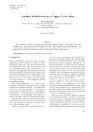
Matthew K. Schwiebert received the M.S. degree<br />
in mechanical engineering from the University of<br />
Michigan, in 1990.<br />
He joined Hewlett-Packard in 1990, where he is<br />
currently a Manufacturing Development Engineer at<br />
the Electronic Assembly Development Center, Palo<br />
Alto, CA. He h<strong>as</strong> several publications and patents<br />
pending in the are<strong>as</strong> of solder bumping, electromechanical<br />
interconnect, and electronic packaging.