Installation Manual - SECO-LARM
Installation Manual - SECO-LARM
Installation Manual - SECO-LARM

You also want an ePaper? Increase the reach of your titles
YUMPU automatically turns print PDFs into web optimized ePapers that Google loves.
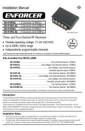
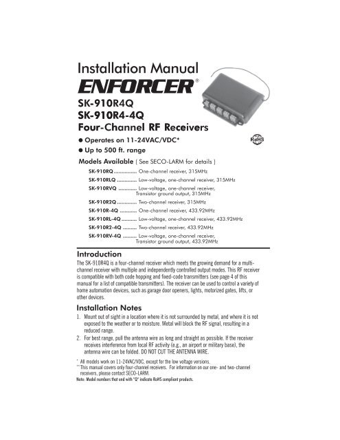
<strong>Installation</strong> <strong>Manual</strong><br />
ENFORCER®<br />
SK -910R4Q<br />
SK -910R4-4Q<br />
Four- r Channel l RF R eceivers<br />
e e<br />
● Operates on 11-24VAC/VDC*<br />
● Up to 500 ft. range<br />
Models Available ( See <strong>SECO</strong>-<strong>LARM</strong> for details )<br />
SK-910RQ ............... One-channel receiver, 315MHz<br />
SK-910RLQ ............. Low-voltage, one-channel receiver, 315MHz<br />
SK-910RVQ ............ Low-voltage, one-channel receiver,<br />
Transistor ground output, 315MHz<br />
SK-910R2Q ............. Two-channel receiver, 315MHz<br />
SK-910R-4Q ........... One-channel receiver, 433.92MHz<br />
SK-910RL-4Q .......... Low-voltage, one-channel receiver, 433.92MHz<br />
SK-910R2-4Q ......... Two-channel receiver, 433.92MHz<br />
SK-910RV-4Q ......... Low-voltage, one-channel receiver,<br />
Transistor ground output, 433.92MHz<br />
Introduction<br />
The SK-910R4Q is a four-channel receiver which meets the growing demand for a multichannel<br />
receiver with multiple and independently controlled output modes. This RF receiver<br />
is compatible with both code hopping and fixed-code transmitters (see page 4 of this<br />
manual for a list of compatible transmitters). The receiver can be used to control a variety of<br />
home automation devices, such as garage door openers, lights, motorized gates, lifts, or<br />
other devices.<br />
<strong>Installation</strong> Notes<br />
1. Mount out of sight in a location where it is not surrounded by metal, and where it is not<br />
exposed to the weather or to moisture. Metal will block the RF signal, resulting in a<br />
reduced range.<br />
2. For best range, pull the antenna wire as long and straight as possible. If the receiver<br />
receives interference from local RF activity (e.g., an airport or military base), the<br />
antenna wire can be folded. DO NOT CUT THE ANTENNA WIRE.<br />
*<br />
All models work on 11-24VAC/VDC, except for the low voltage versions.<br />
**<br />
This manual covers only four-channel receivers. For information on our one- and two-channel<br />
receivers, please contact <strong>SECO</strong>-<strong>LARM</strong>.<br />
Note: Model numbers that end with "Q" indicate RoHS compliant products.
Code Learning a New Transmitter Button<br />
Each receiver channel can learn the codes of up to 15 different transmitter buttons on a first-in, first-out basis. Below is<br />
the procedure for code learning a new transmitter button. The same procedure applies to all the receiver’s four channels.<br />
1. Press the mode switch of the desired channel to be programmed for 3 seconds or more. The channel’s red LED will<br />
start to flash quickly to indicate that it is in the learning mode.<br />
2. While the red LED is quickly flashing, press the button of the transmitter to be learned once. The red LED will flash<br />
once to indicate a successful learning of that button’s code.<br />
NOTE: a) The mode switches can be found at the rear of the receiver’s case (see Fig. 1). The switch marked #1<br />
represents the mode switch for channel 1, switch #2 is the mode switch for channel 2, and so on.<br />
b) The channel’s red LED will flash a maximum of 15 seconds. If no transmitter button is pressed during<br />
this time, the receiver will exit the code-learning mode, and the red LED will turn off.<br />
c) If the code being learned has already been learned, the red LED for the channel which learned the code<br />
will turn steady ON, and the code will not be learned a second time.<br />
d) Each channel can learn the codes of a maximum of 15 transmitter buttons. If you attempt to learn a<br />
sixteenth button, the earliest code learned will be deleted.<br />
Channel Memory Clear<br />
To clear all codes in the channel’s memory, enter the channel learning mode first, then press the channel mode switch for<br />
3 or more seconds again. The LED flashes twice to indicate that all codes associated with that channel are now deleted.<br />
Channel Memory Display<br />
To see how many codes have been learned in a channel, press that channel’s mode switch once. The number of codes<br />
stored in the channel’s memory is equal to the number of LED flashes.<br />
Programming Each Channel Relay Output Mode<br />
Each receiver’s channel can be programmed for one of four different modes, and each individual channel may operate at<br />
a different output mode, depending on the user’s application. Applications are as follows:<br />
• Timed Output — Press the transmitter button once. The timed output relay will activate from 1 ~60 seconds,<br />
depending on how long the timed output duration is set (Factory default is 1-second timed output.).<br />
• Toggle Output— Works much like a toggle switch to turn a device ON & OFF alternately. Press the transmitter button<br />
once, and the relay turns on. Press a compatible transmitter button again, and the relay turns off.<br />
• Latch Output— Press the transmitter button once, and the relay turns on and stays on. The relay will remain on until<br />
the appropriate channel mode switch is pressed once to reset, regardless of whether a compatible transmitter<br />
button is pressed again or not.<br />
• Validity Output— The channel will turn the relay ON for as long as the transmitter button is pressed.<br />
Note: Care must be taken when using validity output. Due to possible interference or drops in transmitter battery<br />
power while the transmitter button is continuously pressed (even for short periods of time), the receiver may<br />
lose the transmitter’s signal and turn the relay off.<br />
To program each channel output mode, press the programming mode switch once (switch #5, see Fig. 1). Each<br />
channel’s red LED will flash a number of times equal to the output mode that it is in. Below are the channel output LED<br />
flash indicators:<br />
1.) One flash —Timed Output 3.) Three flashes—Latch Output<br />
2.) Two flashes—Toggle Output 4.) Four flashes—Validity Output<br />
Press the mode switch of the desired channel to be programmed a number of times until the required output is achieved.<br />
The programming procedure for all four channels is the same.<br />
To exit programming, press programming mode switch again.<br />
Setting the Timed Output Timer<br />
When a relay output is set to “timed output,” it turns ON for 1 to 60 seconds when a compatible transmitter button is<br />
pressed. To program the output timer, flip the DIP switches in the timer programming switch according to Table 1.<br />
Note: The SK-910R4Q has only one timer. If more than one relay is set to “timed output,” each relay turns ON for the<br />
same amount of time.
CH 3 Mode Switch<br />
CH 2 Mode Switch<br />
CH 1 Mode Switch<br />
Fig. 1<br />
#1 #2 #3 #4 #5<br />
MODE SWITCH<br />
123<br />
ON<br />
CH 4 Mode Switch<br />
Programming Mode Switch<br />
Timer Programming Switch<br />
ON<br />
TIMER<br />
OFF<br />
Table 1- Timer Programming<br />
Switch Setting.<br />
_______________________<br />
Sec. SW1 SW2 SW3<br />
____________________<br />
1* On Off Off<br />
________________________<br />
2 Off On Off<br />
________________________<br />
3 Off Off On<br />
________________________<br />
4 On Off On<br />
________________________<br />
5 Off On On<br />
________________________<br />
10 On On Off<br />
________________________<br />
30 Off Off Off<br />
60 On On On<br />
* Default Setting<br />
Power Input<br />
11~24VAC/VDC<br />
Channel 1<br />
Channel 2<br />
}<br />
}<br />
}<br />
}<br />
}<br />
Status LED<br />
Channel 4<br />
Channel 3<br />
Channel Mode Switch Operation (one per channel)<br />
• Learn mode — Press and hold the switch for three seconds or more.<br />
• Clear memory — Press and hold the switch for three seconds or more, then when the LED starts flashing, press again<br />
for three seconds to delete all previously learned codes.<br />
• Reset latched output — If this channel was programmed for latch output, once the relay is turned on with a<br />
transmitter button, press the mode switch of that channel once to turn the relay OFF.<br />
• Memory Display — Press and release the mode switch to show the number of codes stored. The LED will flash a<br />
number of times corresponding to the number of codes stored.<br />
LED Indication (one per channel)<br />
If optional antenna is used LP3<br />
must be cut and the antenna<br />
slot on the receiver case must<br />
be chip off to accomodate the<br />
extended range antenna wire<br />
(see Fig. 1).<br />
• Steady ON — Senses signal from a transmitter button or indicates a transmitter button’s code already exists in the<br />
receiver’s memory during code learning.<br />
• Fast flash — In the code-learning mode or channel memory display mode, or during the programming channel output<br />
mode.<br />
• One flash — A transmitter button’s code was learned, or the relay is in time output mode.<br />
• Two flashes — All previously learned transmitter button codes were deleted, or the relay is in toggle output mode.<br />
• Three flashes — Latched output.<br />
• Four flashes — Validity output.<br />
• 0~15 flashes — In the normal operation mode, pressing the channel mode switch (1~4) once will display the<br />
number of codes learned.<br />
Extended Range Antennas<br />
Two antennas are available to extend the range of the SK-910R4Q receiver:<br />
SK-91ERSWQ Extends RF receiver range up to 800 feet (open air) with existing remotes.<br />
SK-91ERSDQ Extends RF receiver range up to 1,200 feet (open air) with existing remotes.<br />
These antennas come with a 9’ cable which easily plugs into the 3-pin antenna port located on the RF receiver.<br />
Note: a) If an extended range antenna is used, the “LP3” on the receiver PC board must be cut.<br />
b) Actual antenna range will vary greatly depending on the operating environment.<br />
SK-91ERSWQ<br />
SK-91ERSDQ
Typical Applications:<br />
Positive Output:<br />
COM<br />
NC<br />
NO<br />
-<br />
+<br />
}<br />
Positive Power Source<br />
Positive Power Output<br />
Power for SK-910R4Q<br />
Negative Output:<br />
COM Negative Power Source<br />
NC<br />
NO Negative Power Output<br />
-<br />
+<br />
} Power for SK-910R4Q<br />
11~24 VAC/VDC power input, 24VAC output driving a motor: 11~24 VAC/VDC power input, 24VDC output driving a motor:<br />
COM 24VAC (1) Input 24VAC (2)<br />
COM 24VDC (1) Input 24VDC (2)<br />
NC<br />
2<br />
NC<br />
2<br />
NO<br />
Motor<br />
1<br />
NO<br />
Motor<br />
1<br />
- 11~24 VAC/VDC Power<br />
- 11~24 VAC/VDC Power<br />
+ } for SK-910R4Q<br />
+ } for SK-910R4Q<br />
12VDC power input, 12VDC positive output:<br />
Typical N.C. application (access control).<br />
COM<br />
NC<br />
NO<br />
-<br />
+<br />
12VDC power input, 12VDC positive output:<br />
(-)<br />
COM<br />
12VDC (2)<br />
(+)<br />
NC<br />
2<br />
ENFORCER ®<br />
NO<br />
Motor<br />
(E-941SA-1200 Electromagnetic Lock)<br />
1<br />
-<br />
} 12VDC Power for SK-910R4Q<br />
+ } 12VDC Power for SK-910R4Q<br />
General Specifications<br />
Operating Frequency: 315MHz ( SK-910R4Q ), 433 92MHz ( SK-910R4-4Q )<br />
Memory Capacity: 15 transmitter button codes per channel, 60 per receiver.<br />
Operating Voltage: 11VDC ~ 24VDC or 11VAC ~ 24VAC<br />
Operating Current: 8 mA @ 12VDC (standby), 30mA/channel @ 12VDC (activated)<br />
Relay Contact Rating: Form ‘C’ type; 10A @ 24VDC or 120VAC per channel<br />
Connectors: Screw Terminals, +, –, with N.O., N.C., and COM per channel<br />
Dimensions: 5.3” x 3 9” x 1.1” (135 x 100 x 27.5 mm)<br />
Compatible Transmitters<br />
Fixed-Code: 68 billion codes.<br />
CODEBUMP TM : 18 quintillion (1.8 x 10 19 ) codes<br />
315MHz<br />
SK-919 Series Fixed Code<br />
SK-917 Series CODEBUMP<br />
433.92MHz<br />
SK-939 Series Fixed Code<br />
SK-937 Series CODEBUMP<br />
WARRANTY: This <strong>SECO</strong>-<strong>LARM</strong> product is warranted against defects in material and workmanship while used in normal service for a period of one (1)<br />
year from the date of sale to the original consumer customer. <strong>SECO</strong>-<strong>LARM</strong>’s obligation is limited to the repair or replacement of any defective part if the unit is<br />
returned, transportation prepaid, to <strong>SECO</strong>-<strong>LARM</strong>.<br />
This Warranty is void if damage is caused by or attributed to acts of God, physical or electrical misuse or abuse, neglect, repair, or alteration, improper or<br />
abnormal usage, or faulty installation, or if for any other reason <strong>SECO</strong>-<strong>LARM</strong> determines that such equipment is not operating properly as a result of causes<br />
other than defects in material and workmanship.<br />
The sole obligation of <strong>SECO</strong>-<strong>LARM</strong>, and the purchaser’s exclusive remedy, shall be limited to replacement or repair only, at <strong>SECO</strong>-<strong>LARM</strong>’s option. In no event<br />
shall <strong>SECO</strong>-<strong>LARM</strong> be liable for any special, collateral, incidental, or consequential personal or property damages of any kind to the purchaser or anyone else.<br />
NOTICE: The information and specifications printed in this manual are current at the time of publication. However, the <strong>SECO</strong>-<strong>LARM</strong> policy is one<br />
of continual development and improvement. For this reason, <strong>SECO</strong>-<strong>LARM</strong> reserves the right to change specifications without notice. <strong>SECO</strong>-<strong>LARM</strong> is<br />
also not responsible for misprints or typographical errors.<br />
Copyright © 2006 <strong>SECO</strong>-<strong>LARM</strong> U.S.A., Inc. All rights reserved. This material may not be reproduced or copied, in whole or in part, without the written<br />
permission of <strong>SECO</strong>-<strong>LARM</strong>.<br />
<strong>SECO</strong>-<strong>LARM</strong> - ® U.S.A., ., Inc.<br />
16842 Millikan Avenue, Irvine, CA 92606<br />
Tel: 800-662-0800 / 949-261-2999 Fax: 949-261-7326<br />
Website: www.seco-larm.com<br />
E-mail: sales@seco-larm.com<br />
FILE: DT/DTP/MtiSk9104Q_06A.pmd<br />
ORDER PART# 762-100-1%<br />
PITSW1