Experiment Manual Sample Pages (PDF) - Thames & Kosmos
Experiment Manual Sample Pages (PDF) - Thames & Kosmos
Experiment Manual Sample Pages (PDF) - Thames & Kosmos

You also want an ePaper? Increase the reach of your titles
YUMPU automatically turns print PDFs into web optimized ePapers that Google loves.
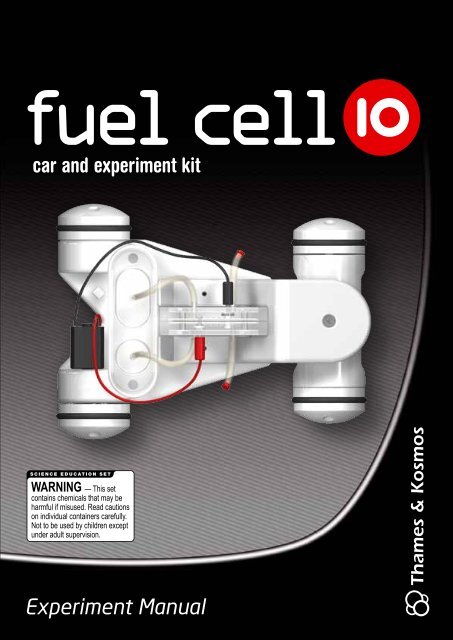
<strong>Experiment</strong> <strong>Manual</strong>
The Solar-Hydrogen Innovation Chapter 1<br />
Concept Fuel Cell Car Process<br />
This fuel cell car works in a two-step process. First, the fuel<br />
cell splits water into hydrogen and oxygen and those gases<br />
are stored in tanks. When the electric motor is connected<br />
to the fuel cell, the fuel cell combines those two gases into<br />
water, which produces electricity to run the motor. We can<br />
also use our car to investigate other alternative electric car<br />
concepts.<br />
Fuel Cell<br />
<strong>Experiment</strong> <strong>Manual</strong><br />
Electric Motor<br />
Fuel cell technology in the model<br />
To power the fuel cell, we will<br />
start with the sun, because<br />
the fuel for the fuel cell car is<br />
generated using solar power.<br />
1. The solar panel generates<br />
electricity from sunlight.<br />
2. The electricity from the<br />
solar panel is used for electrolysis<br />
of water.<br />
3. The hydrogen gas produced<br />
during electrolysis is<br />
the fuel for the fuel cell.<br />
4. The fuel cell uses hydrogen<br />
and oxygen to generate<br />
electricity to power the car’s<br />
electric motor.<br />
7
Screw<br />
with<br />
Washer<br />
8<br />
Chapter 1 Kit Contents<br />
Fuel Cell 10<br />
Overview of Components<br />
Display Stand<br />
Pulley Wheels<br />
Front Axle<br />
Display Stand Feet<br />
Motor, Transmission,<br />
and Wheel<br />
Screws<br />
Fuel Cell 10<br />
Digital<br />
Multimeter<br />
Chassis<br />
Fuel Cell<br />
Rubber Belt
Kit Contents<br />
Wheels<br />
Solar Panel<br />
Water Tank<br />
Wires, 30 cm<br />
Support<br />
Roller Caps<br />
<strong>Experiment</strong> <strong>Manual</strong><br />
Gas Tanks<br />
Hose Plugs<br />
Battery Holder<br />
Wires, 160 cm<br />
Syringe<br />
Chapter 1<br />
Syringe Tip<br />
Axles<br />
If you<br />
are missing<br />
a part, please<br />
contact <strong>Thames</strong> &<br />
<strong>Kosmos</strong> Technical<br />
Support.<br />
Hose<br />
9
<strong>Experiment</strong><br />
5<br />
When the sun is not shining,<br />
you can also produce<br />
fuel with battery power.<br />
· Connect the red battery<br />
terminal to the red<br />
oxygen O 2 socket of the<br />
fuel cell.<br />
· Connect the black<br />
battery terminal to the<br />
black hydrogen H 2 socket.<br />
Checking the Gas<br />
Production<br />
Now electrolysis begins in the<br />
fuel cell, which is the splitting<br />
of water into its elements, hydrogen<br />
and oxygen. The water<br />
that remains in the tubes is<br />
pushed from the cell through<br />
the long hoses to the gas<br />
tanks and the water tank by<br />
the gas that is produced. The<br />
larger tank fills with hydrogen<br />
gas, the smaller one with oxygen.<br />
After just a few minutes,<br />
you will be able to see how the<br />
gases push the water down in<br />
their storage tanks and the<br />
water level in the water tank<br />
starts to rise.<br />
When the first bubbles rise<br />
out of the gas tanks to the<br />
water’s surface, the tanks are<br />
full.<br />
Remove the cables between<br />
the fuel cell and solar panel.<br />
36<br />
Chapter 4<br />
<strong>Experiment</strong>: Hydrogen Generation<br />
Production of Fuel with<br />
Battery Current<br />
Do It! Produce Fuel with Battery Power<br />
Concept The Fuel Cell Generates Fuel<br />
Fuel Cell as Fuel<br />
Generator<br />
Batteries<br />
Fuel Cell 10<br />
Fuel Cell<br />
Battery Power Generator Fuel<br />
Note:<br />
The distilled water<br />
is pictured here in<br />
blue so you can see<br />
it more clearly.<br />
Oxygen<br />
6<br />
Hydrogen
Chapter 9 Theory<br />
Structure and Function<br />
of a Solar Cell<br />
Doping the Silicon<br />
To create solar cells from the<br />
highly pure silicon wafers,<br />
they have to be somewhat<br />
“impurified” again. This process<br />
is known as doping. It<br />
involves vapor-deposition of<br />
tiny doses of pure elemental<br />
phosphorus on one surface of<br />
the wafer, and boron on the<br />
other surface. The proportion<br />
of these doping elements to<br />
the silicon is about equivalent<br />
to one drop of water in a<br />
swimming pool.<br />
58<br />
Silicon Crystal Lattice<br />
Doped with Phosphorus<br />
In the upper layer, a silicon<br />
atom will be replaced by a<br />
phosphorus atom in a few<br />
spots (above). In its outer<br />
shell, phosphorus has five<br />
electrons. There is one electron<br />
left over, since it can only<br />
Silicon Atom<br />
Fuel Cell 10<br />
Silicon Crystal Lattice<br />
enter into a covalent bond<br />
with four silicon atoms in the<br />
crystal lattice. That is because<br />
silicon is usually tetravalent,<br />
meaning it has four “bonding<br />
arms.”<br />
So the phosphorus atom’s fifth<br />
electron cannot find a bonding<br />
partner, and it is therefore<br />
very loosely attached to<br />
the phosphorus atom. Even at<br />
room temperature, the bond<br />
will be easily broken. So silicon<br />
doped in this manner has free<br />
electrons (negative charges)<br />
and is therefore called an ndoped<br />
layer.<br />
The solar cell’s lower layer is<br />
doped with boron in a similar<br />
Silicon Crystal Lattice<br />
Doped with Boron<br />
manner (below). Boron has<br />
three electrons in its outer<br />
shell, each of which enters<br />
into a bond with the neighboring<br />
silicon atom.<br />
There is an electron missing<br />
for a fourth bond, however.<br />
This kind of defect or gap is<br />
known as an “electron hole.”<br />
Even at room temperature, an<br />
electron from a neighboring Si<br />
atom can “jump over” into this<br />
hole, making the hole seem<br />
to move. The conductivity of<br />
the silicon doped in this manner,<br />
in other words, depends<br />
on the mobility of the “holes”<br />
(positive charges). This zone<br />
is known as a p-doped layer.<br />
Both the p-doped and the ndoped<br />
layers conduct well,<br />
and are neutral on their own.<br />
So there is no voltage.<br />
This is how the silicon is manipulated<br />
to make it photoelectrically<br />
sensitive. A look into the<br />
solar cell’s crystal lattice will<br />
show us how it works.<br />
Creating the<br />
Voltage Potential<br />
In the area where the p-<br />
and n-doped layers touch,<br />
a boundary layer known as<br />
a p–n junction forms, where<br />
a few electrons from the ndoped<br />
layer wander over into<br />
the p-doped layer. There, they<br />
replace electrons that are<br />
missing for covalent bonding.<br />
The movement of the electrons<br />
from the n-doped layer
Tests<br />
Solar Panel Voltage<br />
To determine the power of<br />
the solar panel, we will measure<br />
the short circuit voltage<br />
on the V= side of the multimeter<br />
in measurement range<br />
20 (Figure 2). The voltage<br />
will vary depending on the<br />
strength of the light hitting<br />
it, but it should be about 2.8<br />
volts.<br />
Solar Panel Current<br />
We will measure its short circuit<br />
current on the A= side in<br />
the 200m range (Figure 3). The<br />
current will also vary depending<br />
on the amount of light, but<br />
an average current reading is<br />
about 250 mA.<br />
Multiply 0.25 A x 2.8 V to calculate<br />
a power of 0.7 watts.<br />
Fuel Cell Power<br />
To measure the power of the<br />
fuel cell, first fill the tanks<br />
with hydrogen and oxygen.<br />
Instead of connecting the motor,<br />
insert the meter probes<br />
into the cell’s and sockets<br />
and take a reading (Figure<br />
4). Thus, we can calculate the<br />
fuel cell:<br />
Power = Voltage x Current<br />
With 1.4 volts and 16 mA (0.16<br />
A), the power output would be<br />
0.22 watts. The values drop<br />
by half as soon as we hook up<br />
a load (the electric motor) to<br />
the circuit instead of just the<br />
multimeter. Then, the value<br />
readings are called operating<br />
voltage or operating current,<br />
instead of no-load values.<br />
<strong>Experiment</strong> <strong>Manual</strong><br />
Measurements<br />
Chapter 11<br />
Measuring the Solar Panel<br />
and Fuel Cell Output<br />
Measure Solar Panel Voltage<br />
Measure Solar Panel Current<br />
Measure Fuel Cell Voltage<br />
4<br />
2<br />
3<br />
Multimeter Setting<br />
Multimeter Setting<br />
Multimeter Setting<br />
63