Cascade Hadamard based Parallel Sigma-Delta Modulation for ...
Cascade Hadamard based Parallel Sigma-Delta Modulation for ...
Cascade Hadamard based Parallel Sigma-Delta Modulation for ...

Create successful ePaper yourself
Turn your PDF publications into a flip-book with our unique Google optimized e-Paper software.
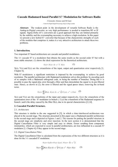
<strong>Cascade</strong> <strong>Hadamard</strong> <strong>based</strong> <strong>Parallel</strong> S <strong>Modulation</strong> <strong>for</strong> Software Radio<br />
J Gonzalo Alonso and M Gani<br />
Centre <strong>for</strong> Digital Signal Processing, King's College London<br />
Abstract: The weakest point in the development of versatile Software Radio is the<br />
Analog-to-Digital converter, as very high per<strong>for</strong>mance is needed to trans<strong>for</strong>m RF or IF<br />
signals. <strong>Sigma</strong>-<strong>Delta</strong> (S) converters are a good approach but they are limited primarily<br />
by the stability and the oversampling necessary to achieve a high resolution. In this paper<br />
we present a new hybrid S converter that because of the characteristic strengths of each<br />
of the modules that comprises it, makes it a very attractive architecture to attack these two<br />
problems.<br />
1. Introduction.<br />
Two important S <strong>based</strong> architectures are cascade and parallel modulators.<br />
The 1-1 cascade S is a modulator that obtains the same results as the second order S but with a<br />
more stable structure. (1) shows the ideal expression <strong>for</strong> the theoretical architecture.<br />
Y(<br />
z)<br />
= X ( z)<br />
− (1 − z<br />
2<br />
) ⋅ E(<br />
z)<br />
− 1<br />
(1)<br />
X(z), Y(z) and E(z) are the z-trans<strong>for</strong>ms of the input, output and quantization error respectively [1,<br />
Chapter 6].<br />
With S modulators a significant restriction is imposed by the oversampling to achieve by good<br />
resolution. The parallel architecture with <strong>Hadamard</strong> modulation solves this problem by encoding each<br />
of m samples with a <strong>Hadamard</strong> orthogonal code, m being the number of branches. Doing this it is<br />
possible to pass the signal plus error through a filter and then demodulate the signal to its pre-filtered<br />
state. Hence, as shown in (2), the error is filtered and the signal passes intact, removing the in-band<br />
noise.<br />
Y(<br />
z)<br />
=<br />
m<br />
−1<br />
−k<br />
∑[ H(<br />
z)<br />
⋅ Ei ( z)<br />
⋅ (1 − z )] ∗U<br />
i(<br />
z)<br />
⋅ z + X ( z)<br />
i = 1<br />
X(z) and Y(z) are the z-trans<strong>for</strong>ms of the input and output respectively, E i (z) the z-trans<strong>for</strong>m of the<br />
quantization error of the S modulator in branch i, U i (z) the z-trans<strong>for</strong>m of the <strong>Hadamard</strong> sequence in<br />
branch i and k the delay caused by the filter H(z), due to its special characteristics [2,3,4].<br />
2. <strong>Cascade</strong>d <strong>Parallel</strong> Structure.<br />
2.1. Architecture<br />
This structure is similar to the one suggested in [5], in which a time-interleaved architecture was<br />
placed in the second stage. The structure presented in this paper uses a <strong>Hadamard</strong> parallel architecture<br />
in the second stage and is depicted in Figures 1 and 2. The reasons <strong>for</strong> putting the parallel structure in<br />
the second stage are simplicity and error rejection. In the next section it is demonstrated that the<br />
Digital Cancellation Filter is very simple and easy to obtain. Errors resulting from component<br />
mismatches, which are expected to occur in parallel architectures, are less influential in a cascade S<br />
modulator [1, Chapter 6] if they appear in the second stage.<br />
2.2. Digital Cancellation Filter.<br />
The Digital Cancellation Filter is calculated from the expressions of the two different structures as it is<br />
done <strong>for</strong> the 1-1 cascaded S modulator.<br />
m<br />
Y z)<br />
= Y ( Z)<br />
+ F ( z)<br />
⋅Y<br />
( ) ;<br />
−1<br />
F ( z)<br />
= −( 1−<br />
z );<br />
(<br />
1 2<br />
z<br />
−1<br />
−k<br />
[ H(<br />
z)<br />
⋅ E′<br />
( z)<br />
⋅ 1( − z )] ∗U<br />
( z)<br />
⋅ z ⋅ F(<br />
z)<br />
X(<br />
z)<br />
(2)<br />
Y(<br />
z)<br />
= ∑ + (3)<br />
i i<br />
i=<br />
1
(3) shows that the quantization error resulting from the <strong>Parallel</strong> Structure, is filtered and shaped in<br />
second order, whilst it does not affect the signal.<br />
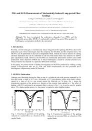
X(z)<br />
1<br />
Q<br />
1 - z -1<br />
Y 1<br />
(z)<br />
z -1<br />
Y(z)<br />
E(z)<br />
<strong>Parallel</strong><br />
Structure<br />
F(z)<br />
Y 2<br />
(z)<br />
Figure 1. <strong>Cascade</strong>d Σ∆ Modulator with <strong>Parallel</strong> second Stage.<br />
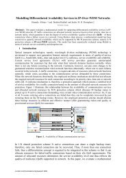
e[n]<br />
SD<br />
h[n]<br />
u 0<br />
[n]<br />
u 0<br />
[n-k]<br />
SD<br />
h[n]<br />
u 1<br />
[n]<br />
u 1<br />
[n-k]<br />
SD<br />
h[n]<br />
y 2<br />
[n]<br />
u m<br />
[n]<br />
u m<br />
[n-k]<br />
2.3 Limitations.<br />
Figure 2: Details of parallel structure from Figure 1<br />
This second order shaping of the quantization error typical of the parallel structure does not offer good<br />
per<strong>for</strong>mance in all cases.<br />
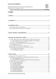
Figure 3. Periodogram of the output <strong>for</strong> the proposed<br />
architecture, the cascade and the parallel S<br />
modulators.<br />
Figure 4. Zoom in the low frequencies of Figure 3.
Looking the shape of the noise in each case (figure 3) and noting that the error that affects the signal is<br />
the integration of the error from DC to the sampling frequency divided by two times the oversampling<br />
ratio (2*OSR), it is obvious that depending on the OSR the cascaded parallel structure studied is not<br />
always the best solution. In one extreme, not having any oversampling, the noise integrated will be<br />
from DC to f s /2, which means that the best per<strong>for</strong>mance will be given by the parallel S modulator, as<br />
it has flattened noise throughout the spectrum. In cases having a large OSR the best solution will be<br />
the cascade with its second order shaping of the noise, as in the lower frequencies the noise goes<br />
below that achieved by the cascaded parallel implementation, whilst the simple parallel does not have<br />
the characteristic noise shaping of S modulators near DC (figure 4).<br />
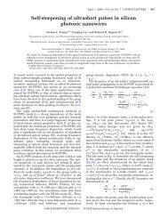
There<strong>for</strong>e, there is a certain range of the OSR in which the per<strong>for</strong>mance is better producing a stable<br />
structure that does not need as much oversampling as the cascade S modulator (as shown in figure<br />
5), relaxing one of the most important characteristics of S converters that makes it impossible to<br />
convert RF signals.<br />
Figure 4. Dynamic Range plot<strong>for</strong> the proposed architecture and the Second Order S ADC.<br />
3. Conclusions.<br />
We have studied a novel hybrid architecture that relaxes the per<strong>for</strong>mance requirements of both<br />
structures which comprises it. Less oversampling ratio is needed than the second order S modulator<br />
to achieve the same SNDR; and it is more stable than the parallel structure because this component is<br />
placed in the second stage of the cascade [1, Chapter 6]. The drawback of this hybrid is that there exist<br />
some ranges of OSR in which its per<strong>for</strong>mance is marginally inferior to the existing implementations,<br />
though its per<strong>for</strong>mance is generally superior.<br />
References.<br />
[1] S. R. Norsworthy, R. Schreier and G. C. Temes, <strong>Delta</strong>-<strong>Sigma</strong> Data Converters: Theory, Design<br />
and Simulation, IEEE Press, IEEE Circuits and Systems Society, 1997.<br />
[2] I. Galton, H. T. Jensen, “<strong>Delta</strong>-<strong>Sigma</strong> Modulator Based A/D Conversion without Oversampling”,<br />
IEEE Trans. Circuits Syst. II, Vol 42, No 12, Dec 1995, pp. 773-784.<br />
[3] I. Galton, H. T. Jensen, “Oversampling <strong>Parallel</strong> <strong>Delta</strong>-<strong>Sigma</strong> Modulator A/D Conversion”, IEEE<br />
Trans. Circuits Syst. II, Vol 43, No 12, Dec 1996, pp. 801-810.<br />
[4] E. T. King, A. Eshraghi, I. Galton & T. S. Fiez, “A Nyquist-Rate <strong>Delta</strong> <strong>Sigma</strong> A/D Converter”,<br />
IEEE J. Solid State Circuits, Vol 33, No 1, Jan 1998, pp 45-52.<br />
[5] X. Wang, W. Qin & X. Ling, “<strong>Cascade</strong>d <strong>Parallel</strong> Oversampling <strong>Sigma</strong>-<strong>Delta</strong> Modulators”, IEEE<br />
Trans. Circuits Syst. II, Vol 47, No 2, Feb 2000, pp. 156-161.