Performance Comparison of OFDM and FOFDM Communication ...
Performance Comparison of OFDM and FOFDM Communication ...
Performance Comparison of OFDM and FOFDM Communication ...

Create successful ePaper yourself
Turn your PDF publications into a flip-book with our unique Google optimized e-Paper software.
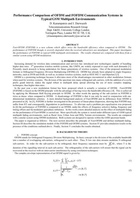
<strong>Performance</strong> <strong>Comparison</strong> <strong>of</strong> <strong>OFDM</strong> <strong>and</strong> F<strong>OFDM</strong> <strong>Communication</strong> Systems in<br />
Typical GSM Multipath Environments<br />
D. Karampatsis <strong>and</strong> I. Darwazeh<br />
Telecommunications Research Group<br />
Dept. E&EE, University College London<br />
Torrington Place, London WC1E 7JE, U.K.<br />
{d.karampatsis,i.darwazeh}@ee.ucl.ac.uk<br />
ABSTRACT<br />
Fast-<strong>OFDM</strong> (F<strong>OFDM</strong>) is a new scheme which <strong>of</strong>fers twice the b<strong>and</strong>width efficiency when compared to <strong>OFDM</strong>. The<br />
performance <strong>of</strong> F<strong>OFDM</strong> though, is severely degraded when the received subcarriers are misaligned. This paper investigates<br />
the performance <strong>of</strong> F<strong>OFDM</strong> in typical GSM multipath environments. The results obtained are compared with those from a<br />
similar system using <strong>OFDM</strong> modulation.<br />
I. INTRODUCTION<br />
Increasing dem<strong>and</strong> for wireless data communication <strong>and</strong> services has introduced new technologies capable <strong>of</strong> h<strong>and</strong>ling<br />
higher data rates. 3 rd generation wireless mobile systems, like UMTS, are widely expected to cope with such dem<strong>and</strong>s [1].<br />
Presently much research is being undertaken for future generations <strong>of</strong> wireless systems. One <strong>of</strong> the proposed modulation<br />
formats is Orthogonal Frequency Division Multiplexing (<strong>OFDM</strong>) [2]. <strong>OFDM</strong> has already been adopted in single frequency<br />
networks, such as DVB <strong>and</strong> DAB, as well as, in indoor wireless systems, such as IEEE 802.11 <strong>and</strong> Hiperlan2 [3].<br />
<strong>OFDM</strong> is a promising technique because it alleviates most <strong>of</strong> the disadvantages encountered in other modulation formats<br />
when used for wireless systems. The division <strong>of</strong> the spectrum into many orthogonal sub-carriers, with the addition <strong>of</strong> a cyclic<br />
prefix guard interval, makes the signal robust to multipath delay spread allowing the use <strong>of</strong> more complex mapping<br />
techniques, thus higher data rates.<br />
In the past year a new modulation format has been proposed which is actually a variation <strong>of</strong> <strong>OFDM</strong>. Fast-<strong>OFDM</strong><br />
(F<strong>OFDM</strong>) is based on the <strong>OFDM</strong> principle with the advantage <strong>of</strong> having twice the b<strong>and</strong>width efficiency [4]. This is achieved<br />
by applying the Minimum Shift Keying principle to <strong>OFDM</strong>. In other words the spacing <strong>of</strong> the sub-carriers in F<strong>OFDM</strong> is<br />
twice as dense when compared to <strong>OFDM</strong>. A disadvantage <strong>of</strong> F<strong>OFDM</strong> is that it can only be used in conjunction with one<br />
dimensional modulation schemes. A more detailed background analysis <strong>of</strong> Fast-<strong>OFDM</strong> <strong>and</strong> its differences from <strong>OFDM</strong> is<br />
presented in [4]. In [5], F<strong>OFDM</strong> is further investigated in the presence <strong>of</strong> linear phase dispersion, showing that F<strong>OFDM</strong> may<br />
suffer from ICI <strong>and</strong> consequently, degradation in performance. To alleviate such a problem pre-equalisation was proposed.<br />
In [6] the performance <strong>of</strong> F<strong>OFDM</strong> is compared to an <strong>OFDM</strong>, under the effects <strong>of</strong>; frequency selective fading, frequency <strong>and</strong><br />
timing <strong>of</strong>fsets <strong>and</strong> IQ modulator gain/phase imbalance. In this work a more detailed analysis on the effect <strong>of</strong> multipath fading<br />
on the performance <strong>of</strong> Fast-<strong>OFDM</strong> is carried out. More specifically the system is tested under different types <strong>of</strong> GSM typical<br />
multipath fading environments, such as Rural Area, Urban Area <strong>and</strong> Hilly Terrain environments. The results are compared<br />
with a similar system using <strong>OFDM</strong> modulation. Both systems are designed to operate within the GSM spectrum b<strong>and</strong>s.<br />
The paper is organised as follows: The next section describes the principle <strong>of</strong> Fast-<strong>OFDM</strong> <strong>and</strong> defines multipath fading.<br />
Section III describes the simulation models <strong>of</strong> the F<strong>OFDM</strong> <strong>and</strong> <strong>OFDM</strong> systems. Section IV provides simulation results in the<br />
presence <strong>of</strong> the conditions outlined above. Finally, Section V concludes the results obtained.<br />
II. BACKGROUND THEORY<br />
a. F<strong>OFDM</strong> concept<br />
<strong>OFDM</strong> st<strong>and</strong>s for Orthogonal Frequency Division Multiplexing. Its basic concept is the division <strong>of</strong> the available b<strong>and</strong>width<br />
into a number <strong>of</strong> overlapping sub-carriers, orthogonal to each other. Thus, N low rate data streams modulate N orthogonal<br />
sub-carriers. In order for the sub-carriers to be orthogonal, their frequency separation must be 1 Hz , where T is the<br />
T<br />
duration <strong>of</strong> the signalling interval in each sub-carrier. The orthogonality <strong>of</strong> the sub-carriers will ensure that the signal can be<br />
recovered at the receiver with no inter-carrier interference by using correlation techniques.<br />
The complex envelope representation <strong>of</strong> an <strong>OFDM</strong> signal is given by:<br />
S<br />
tx<br />
∞<br />
N −1<br />
( t) = ∑ ∑<br />
k=−∞<br />
n=<br />
0<br />
⎧<br />
⎪ 1<br />
gn(<br />
t)<br />
= ⎨ T − T<br />
⎪<br />
⎩0,<br />
an, k gn( t − kT)<br />
(1)<br />
CP<br />
e<br />
2π<br />
nt<br />
T−T CP<br />
, t ∈ [0, T ]<br />
t ∉ [0, T ]<br />
(2)
where, a n,k is the complex symbol transmitted on the n th sub-carrier at the k th signalling interval, N is the number <strong>of</strong> <strong>OFDM</strong><br />
g n<br />
t − kT represents the complex waveform (the complex sub-carrier) used to convey the complex data in the<br />
sub-carriers, ( )<br />
same time slot <strong>and</strong> sub-channel, T is the duration <strong>of</strong> the signalling interval <strong>and</strong> T CP is the duration <strong>of</strong> the cyclic prefix.<br />
F<strong>OFDM</strong> has similar properties to <strong>OFDM</strong> with the difference that in F<strong>OFDM</strong> the frequency separation <strong>of</strong> the sub-carriers is<br />
halved, that is 1 Hz.<br />
2T<br />
The complex envelope representation <strong>of</strong> an F<strong>OFDM</strong> signal is expressed as:<br />
where,<br />
S<br />
tx<br />
∞<br />
N−1<br />
( t) = ∑ ∑an k gn( t − kT)<br />
k=−∞<br />
n=<br />
0<br />
⎧<br />
, (3)<br />
2πnt<br />
j<br />
1 )<br />
⎪<br />
2( T −T ( ) =<br />
e CP<br />
g t<br />
, t ∈[ 0, T ]<br />
n ⎨ T − TCP<br />
⎪<br />
⎩ 0, t ∉[ 0, T ]<br />
a , , represents the complex data conveyed in time slot k <strong>and</strong> sub-channel n <strong>and</strong> ( t kT)<br />
n k<br />
(4)<br />
g n<br />
− represents the complex<br />
waveform (the complex sub-carrier) used to convey the complex data in the same time slot <strong>and</strong> sub-channel, T is the duration<br />
<strong>of</strong> the signalling interval <strong>and</strong> T CP is the duration <strong>of</strong> the cyclic prefix.<br />
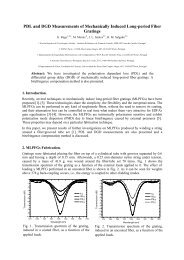
Figure 1, shows the constellation diagram for an 8 subcarrier <strong>OFDM</strong>/BPSK <strong>and</strong> F<strong>OFDM</strong>/BPSK signals. The figure shows<br />
that the real value <strong>of</strong> the data is received correctly, however, due to ICI, additional imaginary components are present. Thus,<br />
the transmitted data can be recovered by taking the real part <strong>of</strong> the received signal. On the other h<strong>and</strong>, when complex<br />
mapping is applied, for example QPSK, there is ICI in both real <strong>and</strong> imaginary part <strong>of</strong> the data, which make signal recovery<br />
difficult [4].<br />
Figure 1 – Constellation diagrams: <strong>OFDM</strong>/BPSK (left) <strong>and</strong> F<strong>OFDM</strong>/BPSK (right) signals<br />
b. Multipath Fading<br />
In a multipath fading environment multiple delay versions <strong>of</strong> the <strong>OFDM</strong>/F<strong>OFDM</strong> frames under different power arrive at the<br />
receiver. The signal out <strong>of</strong> a multipath channel, r(t), is defined as:<br />
⎛ M<br />
⎞<br />
( ) = ⎜ ∑ ( −<br />
− jτ<br />
iωc<br />
r t a β i s t τ i ) e gi<br />
( t)⎟ (5)<br />
⎝ i=<br />
1<br />
⎠<br />
where α is the pathloss attenuation, β<br />
i<br />
is the relative power <strong>of</strong> each echo, τ<br />
i<br />
is the relative delay <strong>of</strong> each echo, plus the<br />
direct path delay τ<br />
0<br />
, s(t) is the complex envelope input signal <strong>and</strong> g i (t) is a r<strong>and</strong>om gain function associated with each echo.<br />
III. F<strong>OFDM</strong> AND <strong>OFDM</strong> SYSTEM MODELLING<br />
The modelling <strong>of</strong> the systems is performed in Agilent Advanced Design System (ADS) simulation s<strong>of</strong>tware.<br />
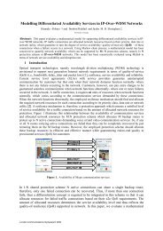
The F<strong>OFDM</strong> system can either be modelled in a “continuous” or “discrete” time model respectively [5]. In this paper the<br />
F<strong>OFDM</strong> system is constructed using FFTs as shown in Figure 2.<br />
R<strong>and</strong>om<br />
Generated<br />
Bits<br />
BPSK<br />
Mapping<br />
IFFT<br />
(N=64)<br />
Transmit<br />
N/2+1 samples<br />
(F<strong>OFDM</strong> only)<br />
Cyclic<br />
Prefix<br />
QAM<br />
Modulator<br />
RF path<br />
Recovered Bits<br />
FFT<br />
(N=64)<br />
Reconstruct<br />
missing<br />
samples<br />
(F<strong>OFDM</strong> only)<br />
Cyclic<br />
Prefix<br />
Removal<br />
QAM<br />
Demodulator<br />
GSM Multipath<br />
Channel Model<br />
Figure 2 – F<strong>OFDM</strong> System Model<br />
In this model the BPSK modulated data is converted from frequency to time-domain representation using a 64-sample IFFT.<br />
The F<strong>OFDM</strong> signal is created by discarding the last N 1<br />
2 − IFFT samples [5]. In this way eq. (3) <strong>and</strong> (4) are satisfied. An
additional N guard interval is then inserted into the F<strong>OFDM</strong> frame using the cyclic prefix property [7]. In this way the<br />
2<br />
F<strong>OFDM</strong> system can withst<strong>and</strong> delay spreads <strong>of</strong> 160 µsec. The system is designed to have an effective data rate <strong>of</strong> 200 kbps.<br />
In ADS setting the sampling time to be 10 µsec will make the b<strong>and</strong>width <strong>of</strong> the F<strong>OFDM</strong> system 100 kHz [8].<br />
Consequently, each <strong>of</strong> the 64 subcarriers will be separated by 1.5625 kHz. Finally, the signal is upconverted to RF using a<br />
QAM modulator. The RF signal is then fed into a channel model which introduces various effects such as multipath fading<br />
<strong>and</strong> Doppler spread. The F<strong>OFDM</strong> RF signal is then received through a QAM demodulator. After the removal <strong>of</strong> the guard<br />
interval the F<strong>OFDM</strong> signal is fed to a 64-sample FFT where the missing N 1<br />
2 − samples are replaced with zeros [5]. The<br />
output <strong>of</strong> the FFT, in the absence <strong>of</strong> any distortion factor, is the recovered BPSK data where its constellation resembles that<br />
<strong>of</strong> Figure 1 (right).<br />
The <strong>OFDM</strong> system model follows the same design procedure <strong>of</strong> the F<strong>OFDM</strong> model. Once more , a 64-sample IFFT with an<br />
additional N samples (for guard interval) are used. In order to have the same data rate as the considered F<strong>OFDM</strong> system,<br />
2<br />
the sampling time is set to 5 µsec. The subcarriers will now be separated by 3.125 kHz, which gives a b<strong>and</strong>width <strong>of</strong> 200 kHz<br />
twice the b<strong>and</strong>width <strong>of</strong> the F<strong>OFDM</strong> system, but within the GSM spectrum b<strong>and</strong>.<br />
IV. RESULTS<br />
a. GSM Typical Rural Area environment<br />
Rural Area environments are defined from the small rms delay spread (maximum relative delay is 0.6 µsec). There are two<br />
GSM typical Rural Area environment modes. The first type has a 6-tap delay channel whereas the second one has a 4-tap<br />
delay channel.<br />
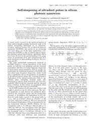
Figure 3 shows the performance <strong>of</strong> F<strong>OFDM</strong> <strong>and</strong> <strong>OFDM</strong> channel in rural area environments under different E b /N 0 values.<br />
The <strong>OFDM</strong> system has a 3dB advantage compared to the F<strong>OFDM</strong> one.<br />
Figure 3 – GSM Typical Rural Area Environment<br />
b. GSM Typical Hilly Terrain environment<br />
Hilly Terrain environments are defined from a mixture <strong>of</strong> low rural area <strong>and</strong> very high delays (0.6 µsec for low <strong>and</strong> 20 µsec<br />
for high). The GSM multipath fading model has four different environments: two modes using 6-taps <strong>and</strong> two modes using<br />
12 taps.<br />
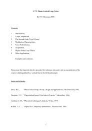
Figure 4 shows the performance <strong>of</strong> both systems under different Hilly Terrain environments over different E b /N 0 values.<br />
The <strong>OFDM</strong> system has a significant advantage in terms <strong>of</strong> error rate over the F<strong>OFDM</strong> system.<br />
Figure 4 – GSM Hilly Terrain Environment
c. GSM Typical Urban Area environment<br />
The tall buildings <strong>of</strong> urban areas obscure the generation <strong>of</strong> high relative delays. GSM typical urban area environments<br />
define a delay <strong>of</strong> 5 µsec, as the highest possible relative delay. Once more there four different urban area fading models are<br />
defined for GSM: two 6-tap <strong>and</strong> two 12-tap modes.<br />
Figure 5 shows the performance <strong>of</strong> both systems under different Urban Area environments over different E b /N 0 values. It is<br />
important to note that both systems have identical performance.<br />
Figure 5 – GSM Typical Urban Environment<br />
V. CONCLUSIONS<br />
This paper is a continuation <strong>of</strong> the work presented in [6]. This work is concentrated on the performance <strong>of</strong> <strong>OFDM</strong>/BPSK<br />
<strong>and</strong> F<strong>OFDM</strong>/BPSK systems over multipath fading environments. The choice <strong>of</strong> GSM typical fading environments was due<br />
to the availability <strong>of</strong> the channel modes. For that reason, both systems were built to operate within the GSM b<strong>and</strong>.<br />
The results show that for high relative delays, as in Hilly Terrain environments, the F<strong>OFDM</strong> system is more susceptible to<br />
errors due to its smaller Intercarrier spacing. On the other h<strong>and</strong> when small-to-medium relative delays are considered, as in<br />
Urban area environments, the performance <strong>of</strong> both systems is identical.<br />
ACKNOWLEDGEMENTS<br />
Dimitrios Karampatsis acknowledges the support <strong>of</strong> Nokia Networks UK.<br />
REFERENCES<br />
[1] João Lima Pinto, Dimitrios Karampatsis <strong>and</strong> Izzat Darwazeh, "GSM Evolution towards 3rd Generation – 2.5 Generation,"<br />
Proc. <strong>of</strong> the International Symposium on Telecommunications (IST 2001), Tehran, Iran, September 2001<br />
[2] Dimitrios Karampatsis <strong>and</strong> Izzat Darwazeh, “<strong>OFDM</strong>; A Possible Technology for 4th Generation Mobile Systems”,<br />
International Symposium on Telecommunication (IST 2001), Tehran, Iran<br />
[3] R. Van Nee <strong>and</strong> R. Prasad, <strong>OFDM</strong> for Wireless Multimedia Applications, Artech House Publishers, 2000<br />
[4] M.R.D. Rodrigues <strong>and</strong> Izzat Darwazeh, “Fast <strong>OFDM</strong>: A Proposal for Doubling the Data Rate <strong>of</strong> <strong>OFDM</strong> Schemes”,<br />
International Conference on <strong>Communication</strong>s, (ICT 2002), Beijing, China, June 2002<br />
[5] D. Karampatsis, M.R.D. Rodrigues <strong>and</strong> I. Darwazeh, "Implications <strong>of</strong> linear phase dispersion on <strong>OFDM</strong> <strong>and</strong> Fast-<strong>OFDM</strong><br />
systems," London <strong>Communication</strong>s Symposium UCL, pp.117-120, London, UK, Sept. 2002<br />
[6] D. Karampatsis, M.R.D. Rodrigues <strong>and</strong> I. Darwazeh, “<strong>Performance</strong> <strong>Comparison</strong> <strong>of</strong> <strong>OFDM</strong> <strong>and</strong> F<strong>OFDM</strong> <strong>Communication</strong><br />
Systems: Effects <strong>of</strong> Frequency Selective Fading, Frequency <strong>and</strong> Timing Offsets <strong>and</strong> I/Q QAM Modulator/Demodulator<br />
Imbalance,” 7 th World Multiconference on Systemics, Cybernetics <strong>and</strong> Informatics (SCI 2003), July 27-30, Orl<strong>and</strong>o, USA<br />
[7] Magnus S<strong>and</strong>ell, Jan-Jaap van de Beek, Per Ola Borjesson, “Timing <strong>and</strong> Frequency Synchronisation in <strong>OFDM</strong> systems<br />
Using the Cyclic Prefix”, Proceedings. <strong>of</strong> International Symposium on Synchronisation, pp. 16-19, Essen, Germany, Dec.<br />
1995<br />
[8] D. Karampatsis <strong>and</strong> I. Darwazeh, “Modelling <strong>and</strong> <strong>Performance</strong> Assessment <strong>of</strong> <strong>OFDM</strong> Systems by Simulation,” Proc.<br />
International Conference on Telecommunications 2002, vol. 2, pp. 420-424, Beijing, China