Lutron Wireless Ceiling Mount Sensor Spec Sheet - LED Source
Lutron Wireless Ceiling Mount Sensor Spec Sheet - LED Source
Lutron Wireless Ceiling Mount Sensor Spec Sheet - LED Source

Create successful ePaper yourself
Turn your PDF publications into a flip-book with our unique Google optimized e-Paper software.
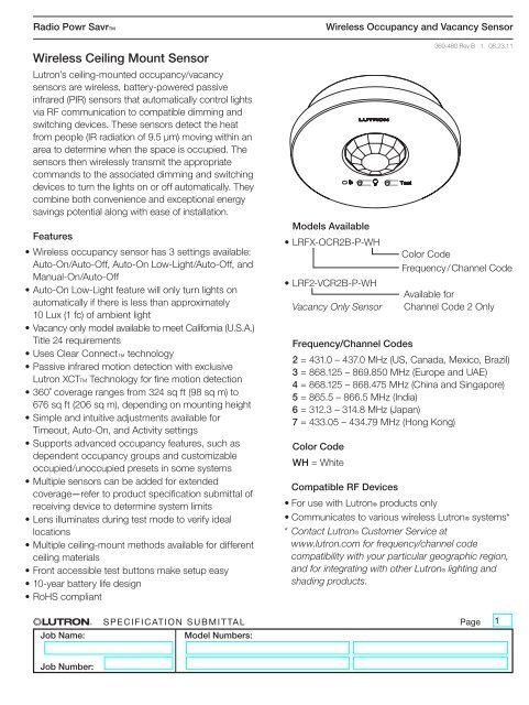
Radio Powr SavrTM<br />
<strong>Wireless</strong> <strong>Ceiling</strong> <strong>Mount</strong> <strong>Sensor</strong><br />
<strong>Lutron</strong>’s ceiling-mounted occupancy/vacancy<br />
sensors are wireless, battery-powered passive<br />
infrared (PIR) sensors that automatically control lights<br />
via RF communication to compatible dimming and<br />
switching devices. These sensors detect the heat<br />
from people (IR radiation of 9.5 μm) moving within an<br />
area to determine when the space is occupied. The<br />
sensors then wirelessly transmit the appropriate<br />
commands to the associated dimming and switching<br />
devices to turn the lights on or off automatically. They<br />
combine both convenience and exceptional energy<br />
savings potential along with ease of installation.<br />
Features<br />
• <strong>Wireless</strong> occupancy sensor has 3 settings available:<br />
Auto-On/Auto-Off, Auto-On Low-Light/Auto-Off, and<br />
Manual-On/Auto-Off<br />
• Auto-On Low-Light feature will only turn lights on<br />
automatically if there is less than approximately<br />
10 Lux (1 fc) of ambient light<br />
• Vacancy only model available to meet California (U.S.A.)<br />
Title 24 requirements<br />
• Uses Clear Connect technology<br />
• Passive infrared motion detection with exclusive<br />
<strong>Lutron</strong> XCTTM Technology for fine motion detection<br />
• 360˚ coverage ranges from 324 sq ft (98 sq m) to<br />
676 sq ft (206 sq m), depending on mounting height<br />
• Simple and intuitive adjustments available for<br />
Timeout, Auto-On, and Activity settings<br />
• Supports advanced occupancy features, such as<br />
dependent occupancy groups and customizable<br />
occupied/unoccupied presets in some systems<br />
• Multiple sensors can be added for extended<br />
coverage—refer to product specification submittal of<br />
receiving device to determine system limits<br />
• Lens illuminates during test mode to verify ideal<br />
locations<br />
• Multiple ceiling-mount methods available for different<br />
ceiling materials<br />
• Front accessible test buttons make setup easy<br />
• 10-year battery life design<br />
• RoHS compliant<br />
<strong>Wireless</strong> Occupancy and Vacancy <strong>Sensor</strong><br />
Models Available<br />
• LRFX-OCR2B-P-WH<br />
• LRF2-VCR2B-P-WH<br />
Vacancy Only <strong>Sensor</strong><br />
369-480 Rev B 1 08.23.11<br />
Frequency/Channel Codes<br />
2 = 431.0 – 437.0 MHz (US, Canada, Mexico, Brazil)<br />
3 = 868.125 – 869.850 MHz (Europe and UAE)<br />
4 = 868.125 – 868.475 MHz (China and Singapore)<br />
5 = 865.5 – 866.5 MHz (India)<br />
6 = 312.3 – 314.8 MHz (Japan)<br />
7 = 433.05 – 434.79 MHz (Hong Kong)<br />
Color Code<br />
WH = White<br />
Color Code<br />
Frequency / Channel Code<br />
Available for<br />
Channel Code 2 Only<br />
Compatible RF Devices<br />
• For use with <strong>Lutron</strong>® products only<br />
• Communicates to various wireless <strong>Lutron</strong>® systems*<br />
* Contact <strong>Lutron</strong>® Customer Service at<br />
www.lutron.com for frequency/channel code<br />
compatibility with your particular geographic region,<br />
and for integrating with other <strong>Lutron</strong>® lighting and<br />
shading products.<br />
Job Name:<br />
<strong>Spec</strong>ification Submittal<br />
Model Numbers:<br />
Page<br />
Job Number:
Radio Powr SavrTM<br />
<strong>Spec</strong>ifications<br />
Regulatory<br />
• <strong>Lutron</strong>R Quality Systems Registered to<br />
ISO 9001:2008<br />
Standards<br />
LRF2-<br />
• FCC certified<br />
• IC certified<br />
• COFETEL certified<br />
• ANATEL certified<br />
• SUTEL certified<br />
• Meets CA (U.S.A.) Energy Commission Title 24<br />
requirements<br />
LRF3-<br />
• CE Marked (European Union) [expected Q4 2011]<br />
• TRA Type Approved (United Arab Emirates)<br />
[expected Q4 2011]<br />
LRF4-<br />
• SRRC Type Approved (Mainland China) [expected<br />
Q4 2011]<br />
• iDA Registered (Singapore) [expected Q4 2011]<br />
LRF5-<br />
• WPC Type Approved (India)<br />
LRF6-<br />
• <br />
007YUUL0689<br />
LRF7-<br />
• FCC certified<br />
Power/Performance<br />
• Operating voltage: 3 V -<br />
• Operating current: 14 μA nominal<br />
• Requires one CR 123 lithium battery<br />
• 10-year battery life design<br />
• Non-volatile memory (saved changes are stored<br />
during power loss)<br />
Environment<br />
• Temperature: 32 ˚F to 104 ˚F (0 ˚C to 40 ˚C)<br />
• For indoor use only<br />
<strong>Wireless</strong> Occupancy and Vacancy <strong>Sensor</strong><br />
369-480 Rev B 2 08.23.11<br />
Range<br />
• LRF2, LRF3, LRF4, LRF5, LRF7<br />
Local load controls must be located within 60 ft<br />
(18 m) line of sight, or 30 ft (9 m), through walls, of<br />
a sensor.<br />
• LRF6<br />
Local load controls must be located within 40 ft<br />
(12.2 m) line of sight or 23 ft (7 m), through walls, of<br />
a sensor.<br />
<strong>Sensor</strong> Coverage Test<br />
• Front accessible test button<br />
• Lens illuminates orange in response to motion<br />
during test mode and is visible from 60 ft (18 m)<br />
<strong>Wireless</strong> Communication Test<br />
• Front accessible test button<br />
• Turn associated loads on and off<br />
Timeout Options<br />
• 1 minute *<br />
• 5 minutes<br />
• 15 minutes – default setting<br />
• 30 minutes<br />
Auto-On Options (Occupancy Versions Only)<br />
• “Enabled” * – <strong>Sensor</strong> turns lights ON and OFF<br />
automatically – default setting.<br />
• “Low Light” – <strong>Sensor</strong> turns lights ON automatically<br />
only in low ambient light conditions. <strong>Sensor</strong> turns<br />
lights OFF automatically.<br />
• “Disabled” ** – Lights must be turned ON manually<br />
from dimming or switching device. <strong>Sensor</strong> turns<br />
lights OFF automatically.<br />
Activity Options<br />
• Low Activity ( ) – default setting<br />
• Medium Activity ( )<br />
• High Activity ( )<br />
* Intended for use in high-activity, briefly occupied areas only<br />
** There is a 15-second grace period that begins when the lights are<br />
automatically turned off, during which the lights will automatically turn<br />
back on in response to motion. This grace period is provided as a safety<br />
and convenience feature in the event the lights turn off while the room is<br />
still occupied, so that the user does not need to manually turn the lights<br />
back on. After 15 seconds, the grace period expires and the lights must<br />
be manually turned on.<br />
Job Name:<br />
<strong>Spec</strong>ification Submittal<br />
Model Numbers:<br />
Page<br />
Job Number:
Radio Powr SavrTM<br />
Dimensions<br />
<strong>Wireless</strong> Occupancy and Vacancy <strong>Sensor</strong><br />
369-480 Rev B 3 08.23.11<br />
1.13 in<br />
(28.7 mm)<br />
3.57 in<br />
(90.7mm)<br />
2.85 in<br />
(72.4 mm)<br />
0.887 in<br />
(22.5 mm)<br />
Job Name:<br />
<strong>Spec</strong>ification Submittal<br />
Model Numbers:<br />
Page<br />
Job Number:
Radio Powr SavrTM<br />
<strong>Wireless</strong> Occupancy and Vacancy <strong>Sensor</strong><br />
Range Diagrams<br />
369-480 Rev B 4 08.23.11<br />
<strong>Ceiling</strong><br />
8 ft<br />
(2.4 m)<br />
<strong>Ceiling</strong><br />
height<br />
Floor<br />
15 ft<br />
(4.6 m)<br />
12 ft<br />
(3.7 m)<br />
9 ft<br />
(2.7 m)<br />
6 ft<br />
(1.8 m)<br />
3 ft<br />
(0.9 m)<br />
0 ft<br />
(0 m)<br />
3 ft<br />
(0.9 m)<br />
6 ft<br />
(1.8 m)<br />
9 ft<br />
(2.7 m)<br />
12 ft<br />
(3.7 m)<br />
15 ft<br />
(4.6 m)<br />
Radius of Coverage at Floor<br />
<strong>Sensor</strong><br />
Occupant r<br />
18 x 18 ft (5.5 x 5.5 m)<br />
Maximum Room Dimensions<br />
for Complete Coverage when<br />
mounted on an 8 ft (2.4 m) <strong>Ceiling</strong><br />
13 ft (4.0 m)<br />
Radius of Coverage at Floor when<br />
mounted on an 8 ft (2.4 m) <strong>Ceiling</strong><br />
<strong>Sensor</strong> Coverage Chart (for sensor mounted in center of room)<br />
Maximum room dimensions<br />
<strong>Ceiling</strong> height<br />
for complete floor coverage*<br />
8 ft (2.4 m)<br />
9 ft (2.7 m)<br />
10 ft (3.0 m)<br />
12 ft (3.7 m)<br />
18 ft x 18 ft (5.5 m × 5.5 m)<br />
20 ft x 20 ft (6.1 m × 6.1 m)<br />
22 ft x 22 ft (6.7 m × 6.7 m)<br />
26 ft x 26 ft (7.9 m × 7.9 m<br />
324 ft 2 (30.2 m 2 )<br />
400 ft 2 (37.2 m 2 )<br />
484 ft 2 (44.9 m 2 )<br />
676 ft 2 (62.4 m 2 )<br />
* 12 ft (3.7 m) is the recommended maximum mounting height<br />
Job Name:<br />
<strong>Spec</strong>ification Submittal<br />
Model Numbers:<br />
Page<br />
Job Number:
Radio Powr SavrTM<br />
Installation Overview<br />
<strong>Wireless</strong> Occupancy and Vacancy <strong>Sensor</strong><br />
369-480 Rev B 5 08.23.11<br />
<strong>Sensor</strong> Placement<br />
• The sensor’s ability to detect motion requires line of sight of room occupants. The sensor must have an<br />
unobstructed view of the room. DO NOT mount behind or near tall cabinets, shelves, hanging fixtures, ceiling<br />
fans, etc. The sensor cannot see through glass objects such as patio or shower doors.<br />
• Hot objects and moving air currents can affect the sensor’s performance. To ensure proper operation, the sensor<br />
should be mounted at least 4 ft (1.2 m) away from HVAC vents and light bulbs that are below the ceiling line.<br />
• The sensor’s performance depends on a temperature differential between the ambient room temperature and<br />
that of room occupants. Warmer rooms may reduce the sensor’s ability to detect occupants.<br />
• LRF2, LRF3, LRF4, LRF5, LRF7: The sensor should be mounted within 60 ft (18 m) line of sight or 30 ft (9 m)<br />
through walls of the associated dimming and switching receiving devices.<br />
• LRF6: The sensor should be mounted within 40 ft (12.2 m) line of sight or 23 ft (7 m) through walls, of the<br />
associated dimming and switching receiving devices.<br />
<strong>Mount</strong>ing<br />
• Temporary mounting is optional to test sensor coverage and wireless communication before permanently<br />
installing the sensor.<br />
Drop <strong>Ceiling</strong> (Compressed Fiber <strong>Ceiling</strong> Tile)<br />
• The ceiling tile mounting wire is provided for both temporary and permanent mounting of the sensor to ceiling<br />
tiles. It is designed to allow temporary mounting, testing, Installation and repositioning English (if necessary) of the sensor without<br />
damaging a ceiling tile. Once the sensor’s final position has been chosen, the mounting wire should be twisted<br />
to lock the sensor in place permanently.<br />
Cut mounting hole<br />
Solid <strong>Ceiling</strong> (Drywall, Plaster, Concrete, or Wood)<br />
Cut a 3 in to 3 in (76 mm to 76 mm) diameter hole to insert the ceiling<br />
• Temporary mounting: Ten (10) temporary mounting mount strips adapter. can be purchased in the kit L-CMDPIRKIT for<br />
temporarily mounting and testing the sensor.<br />
• Permanent mounting: Screws and anchors (for drywall or plaster) provided to mount sensor.<br />
3 in to 3 in<br />
Recess <strong>Mount</strong><br />
(76 mm to 76 mm)<br />
• Do not recess mount ceiling sensor in a metal surface.<br />
2 Insert ceiling mount adapter<br />
• <strong>Ceiling</strong> mount clamps internally to ceiling. <strong>Sensor</strong> twist-locks into mount, sits flush with ceiling (as shown below).<br />
• Opening is 3 in (76.2 mm) in diameter.<br />
• Purchased as a separate kit: L-CRMK-WH.<br />
1<br />
Installing the <strong>Ceiling</strong> <strong>Mount</strong> Adapter<br />
Insert the ceiling mount adapter into the hole and rotate brackets outwards by<br />
turning screws.<br />
Note: No need<br />
to access top<br />
of ceiling.<br />
Job Name:<br />
3<br />
Using a Philips screwdriver, hand-tighten the brackets, clamping the adapter to<br />
the ceiling. Do not overtighten.<br />
<strong>Spec</strong>ification Submittal<br />
Page<br />
Model Numbers:<br />
Clamp adapter to ceiling<br />
Job Number:
Radio Powr SavrTM<br />
Lens Masking<br />
<strong>Wireless</strong> Occupancy and Vacancy <strong>Sensor</strong><br />
369-480 Rev B 6 08.23.11<br />
Whenever possible, the sensor should be installed in a location where it cannot easily see into areas outside the<br />
intended space, such as hallways or adjacent rooms. If this situation cannot be avoided, portions of the lens<br />
may be masked to block the sensor’s view of the undesired areas. Ten (10) PIR Lens Masks can be purchased<br />
in the kit L-CMDPIRKIT.<br />
Lens sections<br />
shown in gray<br />
have not been<br />
masked<br />
Lens sections<br />
shown in white are<br />
masked with labels<br />
Lens label masking sheet<br />
(L-CMDPIRKIT sold separately)<br />
Job Name:<br />
<strong>Spec</strong>ification Submittal<br />
Model Numbers:<br />
Page<br />
Job Number: