
You also want an ePaper? Increase the reach of your titles
YUMPU automatically turns print PDFs into web optimized ePapers that Google loves.
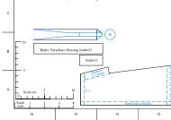
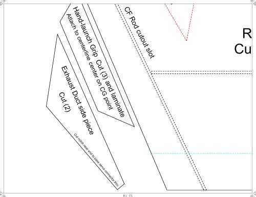
Cut<br />
R<br />
CF Rod cutout slot<br />
Hand-launch Grip Cut (3) and laminate<br />
Attach to centerline center on CG point<br />
Exhaust Duct side piece<br />
Cut (2)<br />
Cut notch near end to pass servo connector thru<br />
R1 C1
CG<br />
CF Rod Rear crossbrace<br />
t elevons and bevel to 45 deg. angle<br />
ed lines indicate elevon cut lines<br />
Rear Wing/ Base (Cut 1)<br />
R1 C2
CF Rod Cutout<br />
Blue lin<br />
Use .210 CF for<br />
Forward Wing/B<br />
Cut (1) Attach<br />
Wing/ Base P<br />
CF Rod Cutout Slot<br />
R1 C3<br />
Mount strips as follows: und
Slot<br />
st center keystone cut (1)<br />
Cut at approx. 60 deg. for tails (no need to be exa<br />
all<br />
ase Piece<br />
to Rear<br />
Piece<br />
Place between tails<br />
until glue dries<br />
Vertical Tail Template<br />
Cockpit front Cut (1)<br />
R1 C4
R1 C5
Control Horns<br />
Cut (2) from 1/32 ply or polycarbon plastic<br />
top<br />
Intake bottom piece Cut (2)<br />
inside edge<br />
bottom<br />
Approximate Servo/Cont<br />
Double check angles to<br />
Cut notch in Fuselag<br />
Double check no fl<br />
R2 C1<br />
Lower cockpit side piece<br />
Cut (2)<br />
Bottom side
ntrol Rod placement<br />
to make sure it is correct<br />
age to pass control rod thru<br />
o flexing or binding<br />
R2 C2
nder leading edge of wing and atop trailing edge of elevons<br />
Green lines indicate elevon vortex generator strip placement<br />
Use thin 2mm balsa strip or cut strips from FFF/depron<br />
R2 C3<br />
Install on top and bottom of both elevons<br />
ines indicate placement of forced washout strips
ear<br />
bottom edge<br />
Cockpit side piece Cut (2)<br />
bottom edge<br />
Exhaust panel Cut (2)<br />
Front Edge<br />
Top Cockpit Piece<br />
Exhau<br />
Cut (1)<br />
Trim to shape<br />
act)<br />
C<br />
ece Cut (2)<br />
R2 C4<br />
Rear Edge
R2 C5
Vertical Tail (Cut 2)<br />
Keep in mind...any angle variation from my build will result in a differ<br />
Also, try to minimize curving of fuselage base piece during fuse cons<br />
9. When placing magnets, space them evenly<br />
along the edges of the Fuselage Base piece.<br />
Use more magnets at the front and rear, and remember to<br />
avoid placing magnets where the CF spars are. My advice is to<br />
mount the magnets to the fuselage base piece before building the fusela<br />
then press the fuselage base piece against the wing/base piece to make<br />
This area should be in back of exhaust panel<br />
R3 C1
for that step...depending on placement of parts, adjustments may need to b<br />
rent result for you. Keep in mind these plans are BETA only.<br />
struction, but a little curvature won't hurt the flight characteristics.<br />
age,<br />
e matching indents at magnet positions.<br />
R3 C2
e made to part sizes on subsequent steps.<br />
Nose Piece Cut (2)<br />
Bottom edge<br />
Front fuselage side Cut (2)<br />
nt<br />
R3 C3
forced washout strip Cut (2) and mount ato<br />
front ed<br />
Intake side piece (Cut 2)<br />
outer edge<br />
Intake Top Piece Cut (2)<br />
r edge<br />
Rear edge<br />
front edge<br />
Top edge<br />
Intake to exhaust transition top piece cut (2)<br />
front edge<br />
R3 C4<br />
bott<br />
Intake to exhaust transition bottom piece C
Internal spine /motor mount pie<br />
R3 C5<br />
forced washout strip Cut (2) and mount und
6. CG measurement on 100% scale is 52cm along centerline from nose ti<br />
7. Materials needed /recommended:<br />
2-3 sheets depron/FFF/sturdyboard<br />
1/32 lite ply for control horns<br />
Polyurethane glue, foam safe CA, UHU Creativ Glue<br />
Thin balsa strips (1/32 I think)<br />
(2) Servos I used Hitec HS-55's<br />
(1) Brushless motor/ESC/Prop - I used HET Typhoon 15/10, EFlite 20 a<br />
(1) Reciever - I used Hitec Electron 6. Minimum Rx would be 4 channe<br />
General Tips<br />
1. All fuselage pieces need to be beveled at varying degrees for proper fit.<br />
2. I recommend using UHU Creativ glue for joining fuselage pieces for flexibility<br />
3. Start <strong>with</strong> 1/2 inch up and down deflection on elevons and adjust to your flyin<br />
4. If possible, use exponential on radio mixing to soften control throws.<br />
5. Have fun! Any questions please email me at dcobra_98@yahoo.com or visit<br />
(3) 61mm .210 CF rods or equivalent length<br />
Scotch Satin tape for elevon hinges, tape over CF rods<br />
(124) 1/8 x 1/16 N48 Neodymium disc magnets (doubled-up) or approx<br />
(1) 3/8 hardwood stick for motor mount.<br />
R4 C1
y.<br />
ng style.<br />
Fuse<br />
discussion thread at http://www.rcgroups.com/forums/showthread.phpt=481872<br />
amp ESC, and APC 8x6 SF prop<br />
l and Transmitter needs to be capable of elevon or V-Tail mixing<br />
ip, or 56cm along wing leading edge from nose tip.<br />
R4 C2<br />
ximately (62) 1/4 x 1/16 magnets.
p Spinal Piece Cut (2)<br />
Aft In<br />
lage Base Piece (Cut 1)<br />
R4 C3
op trailing edge of each elevon (refer to blue sticth lines)<br />
ntake top Cut (2)<br />
Lockheed-Martin F-117<br />
Nighthawk<br />
Copyright 2006 by Paul Albert<br />
Reprinting authorized for personal use only, no commercial u<br />
express permission of author. If you like this design, please<br />
donation for the effort via PayPal to dcobra_98@yahoo.c<br />
This design is free for personal use.<br />
0 CM 8 CM<br />
8CM Rev. 4<br />
R4 C4<br />
rear edge<br />
front edge<br />
edge<br />
top edge<br />
To
A<br />
use <strong>with</strong>out<br />
consider a<br />
com<br />
R4 C5<br />
Cut away corner after motor mount glue dries for better appearance<br />
ce Cut (3) and laminate<br />
Cutout for motor mount stick<br />
Cut stick to length for motor setup used<br />
der leading edge of wing (follow blue stiched lines)