Zero Visibility Operations Planning - DrillSafe
Zero Visibility Operations Planning - DrillSafe
Zero Visibility Operations Planning - DrillSafe

You also want an ePaper? Increase the reach of your titles
YUMPU automatically turns print PDFs into web optimized ePapers that Google loves.
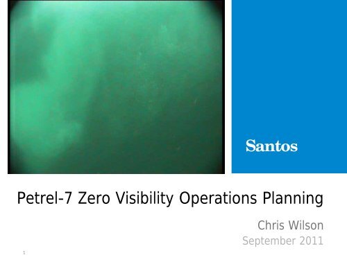
Petrel-7 <strong>Zero</strong> <strong>Visibility</strong> <strong>Operations</strong> <strong>Planning</strong><br />
1<br />
Chris Wilson<br />
September 2011
Glossary of Terms<br />
• TGB – Temporary Guide Base<br />
• PGB – Permanent Guide Base<br />
• ROV – Remotely Operated Vehicle<br />
• Compatt – Acoustic Survey Beacon<br />
• Bucket – Item that holds a Compatt<br />
2
What Causes <strong>Zero</strong> <strong>Visibility</strong> at Petrel<br />
• Active Sedimentary Basin – ongoing sediment deposition<br />
• Strong Currents<br />
- Surface Currents<br />
- Mid water currents Various directions and magnitudes<br />
- Seafloor currents<br />
• Soft seabed<br />
• As a result of the above - offset wells have had to wait on<br />
currents or current induced visibility<br />
3
Petrel Field Location<br />
4
Seabed Survey<br />
Water Depth ~98m LAT<br />
Petrel 7<br />
Water Depth ~94m LAT<br />
5
Petrel 7 Shallow Seismic<br />
Main Line<br />
Petrel 7<br />
Location<br />
8m<br />
200m<br />
Ancient River Channel<br />
In-filled with recent<br />
sediments<br />
6
NW Field Seismic<br />
Main Line<br />
Multiple Ancient River<br />
Channels In-filled<br />
with recent sediments<br />
7
Impact of Environment on <strong>Operations</strong><br />
• Running TGB<br />
- May end-up away from rig centre – due to strong currents<br />
- May be landed on an angle if seabed soft or uneven<br />
- Could sink in the soft seabed<br />
8
Impact of Environment on <strong>Operations</strong><br />
• Running 30” & 20” with PGB<br />
- Could be pushed away from well centre<br />
- PBG angle might be unknown if bulls eyes aren’t visible with ROV<br />
9
Impact of Environment on <strong>Operations</strong><br />
• Running the BOP<br />
- With zero visibility – difficult to determine if rig is over well<br />
centre<br />
10
Impact of Environment on <strong>Operations</strong><br />
• Shallow Gas Monitoring<br />
- Unable to detect gas bubbles with ROV<br />
Uh Oh!<br />
11
Impact of Environment on <strong>Operations</strong><br />
• ROV Damage<br />
- Greater risk of ROV collision and entanglement<br />
12
Solution Criteria<br />
• To overcome the potential problems associated with<br />
Strong Currents and <strong>Zero</strong> <strong>Visibility</strong> a solution had to meet<br />
the following criteria;<br />
1. Determine Relative location of equipment on seabed<br />
(not absolute location)<br />
2. Wireless inclination measurements on TGB and PGB<br />
3. “Pictures” in a zero visibility environment<br />
4. ROV Friendly<br />
5. Easily Deployable<br />
6. Cost Effective (Stena Clyde spread rate on Petrel-7<br />
~$25,000/hour)<br />
13
The “Vision”<br />
14
Recommended Solution - Positioning<br />
• Long Base Line (LBL) array on the seabed<br />
- Provide acoustic “relative” positioning of<br />
subsea components (TGB, PGB, Casing etc.)<br />
• Acoustic Inclinometers<br />
- Provide real time wireless inclination of TGB<br />
and PGB<br />
- Even if the ROV can’t see the bullseyes the<br />
inclination would be known<br />
• LBL beacons on the TGB, PGB and Casing<br />
- LBL beacons can “talk” to the LBL array<br />
triangulating their relative positions<br />
- LBL beacons house the Acoustic<br />
Inclinometers<br />
15
Recommended Solution – <strong>Visibility</strong> (ROV)<br />
• Ultra Short Base Line (USBL) positioning beacon on the ROV<br />
- ROV’s position can be tracked real time – even if the ROV becomes<br />
disoriented or gets lost with zero visibility<br />
- USBL beacon on ROV used to position LBL array on the seafloor<br />
• Multi-beam Sonar on the ROV<br />
- A multi-beam sonar provides a 3D sonar image even in zero visibility<br />
16
USBL vs LBL<br />
• Ultra-short Baseline (USBL)<br />
systems calculate the position of<br />
a subsea target by measuring<br />
the range and bearing from a<br />
vessel mounted transceiver to an<br />
acoustic transponder fitted on<br />
the target e.g. ROV.<br />
• With Long Baseline (LBL)<br />
systems. The baseline is on the<br />
seabed instead of the transceiver<br />
hence the name ‘Long Baseline’.<br />
17
2D Sonar vs Multi-Beam Sonar<br />
2D Sonar<br />
Multi-Beam Sonar<br />
18
Operational Challenges<br />
• Deploying LBL array<br />
- Soft Seabed<br />
- ROV friendly Bucket Structures<br />
- Accurate Positioning<br />
• Acoustic Inclinometer Installation<br />
- Modify TGB and PGB to house Inclinometer<br />
- Perform full Dimensional Check<br />
- ROV Friendly<br />
• ROV Modifications<br />
- Multi-beam Sonar installation and checks<br />
- Installation of a positioning beacon<br />
19
Acoustic Inclinometer Calibration<br />
20
Installation of the LBL Array<br />
• Beacons lowered to seafloor through moonpool on a tugger<br />
• ROV complete with USBL beacon deployed each beacon<br />
21
Array location on the Seabed<br />
22
Multi-Beam Sonar<br />
• Initial results not encouraging<br />
• <strong>Visibility</strong> better than anticipated – main focus was on LBL<br />
system<br />
• Field testing and fault finding difficult due to critical path<br />
operations<br />
• Post operational analysis indicated an earth fault between the<br />
sonar and the ROV which lead to spurious images<br />
23
Mobile Transponder on 20” Casing<br />
• 1 x Mobile Transponder compatt installed on the 20” casing<br />
shoe – inverted to allow easy removal with the ROV.<br />
24
Actual Results – Running Casing<br />
25
Acoustic Inclinometer Performance<br />
26
Acoustic Inclinometers<br />
• Inclinometers moved within the buckets – either caused by<br />
currents or drilling induced vibration<br />
27
Outcomes & Lessons<br />
• LBL Array was easy to deploy<br />
• Rig based USBL beacon not designed to work on ROV –<br />
positioning of LBL beacons not accurate<br />
• Absolute Calibration of the LBL array from a MODU is difficult,<br />
however this was only required this time due to USBL beacon<br />
on ROV not functioning as intended<br />
• Multi-beam sonar did not work as expected (earth fault)<br />
• Inclinometers were effected by currents &/or Drilling Vibration<br />
– giving erroneous readings initially<br />
• Tracking of casing location worked well<br />
• LBL Technology was proven as viable for this application<br />
28
Lessons<br />
• Allow time to field trial multi-beam sonar<br />
• Ensure acoustic inclinometers need to have a snug fit in the<br />
buckets<br />
• ROV positioning beacon to be a field proven dedicated USBL<br />
system – don’t rely on the rigs BOP beacon<br />
• Beacon on the shoe of the 30” casing would not allow casing<br />
to fit through PGB.<br />
29
Questions<br />
30