AAU-Cubesat Ground Station Software Overview - CRN
AAU-Cubesat Ground Station Software Overview - CRN
AAU-Cubesat Ground Station Software Overview - CRN

You also want an ePaper? Increase the reach of your titles
YUMPU automatically turns print PDFs into web optimized ePapers that Google loves.
¡<br />
8 CHAPTER 2. GROUND STATION SERVER<br />
Then the Command type is examined and if it is GsServerControl then the function ServerControl()<br />
is invoked. This function will analyze the header and perform one of the following functions:<br />
KeepMode Will stop server state transition, and thus force the server to remain in the current mode of<br />
operation.<br />
ReleaseMode Will allow the server to follow normal state transition rules again after a KeepMode command.<br />
ForceMode Forces the server to go to the specified mode<br />
SkipLog When this command is issued the server will not request the log as the first action when in contact<br />
with the satellite<br />
SkipFLP When this command is issued the server will not upload a new fligthplan to the satellite on the<br />
next contact.<br />
2.1.3 Antenna Tracking<br />
The antenna tracking software is implemented as an independent thread, and in order to pass reference<br />
variables to it (elevation and azimuth), they must be passed to it through a character device used for inter<br />
process communication. The character device is /dev/dt2811 and the structure to pass through the device is<br />
defined as follows:<br />
struct control<br />
int elevation;<br />
int azimut;<br />
2.1.4 Radio<br />
The ICOM-910H radio is connected to the groundstation PC through a serial port (/dev/ttyS0) and a voltage<br />
level transformer. As implemented in the server the communication is uni-directional, i.e. the PC sends<br />
commands to the radio, but never listens for data or acknowledge signals from the radio. The frame format<br />
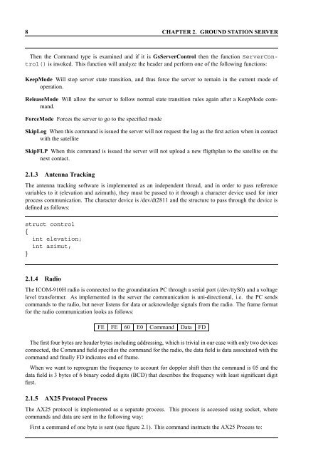
for the radio communication looks as follows:<br />
FE FE 60 E0 Command Data FD<br />
The first four bytes are header bytes including addressing, which is trivial in our case with only two devices<br />
connected, the Command field specifies the command for the radio, the data field is data associated with the<br />
command and finally FD indicates end of frame.<br />
When we want to reprogram the frequency to account for doppler shift then the command is 05 and the<br />
data field is 3 bytes of 6 binary coded digits (BCD) that describes the frequency with least significant digit<br />
first.<br />
2.1.5 AX25 Protocol Process<br />
The AX25 protocol is implemented as a separate process. This process is accessed using socket, where<br />
commands and data are sent in the following way:<br />
First a command of one byte is sent (see figure 2.1). This command instructs the AX25 Process to: