Paper.pdf - COMPASS - FH Aachen
Paper.pdf - COMPASS - FH Aachen
Paper.pdf - COMPASS - FH Aachen
- No tags were found...

You also want an ePaper? Increase the reach of your titles
YUMPU automatically turns print PDFs into web optimized ePapers that Google loves.
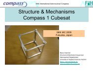
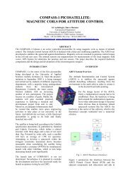
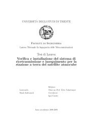
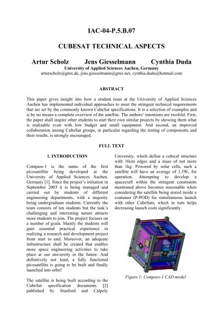
IAC-04-P.5.B.07CUBESAT TECHNICAL ASPECTSArtur Scholz Jens Giesselmann Cynthia DudaUniversity of Applied Sciences <strong>Aachen</strong>, Germanyarturscholz@gmx.de, jens.giesselmann@gmx.net, cynthia.duda@hotmail.comABSTRACTThis paper gives insight into how a student team at the University of Applied Sciences<strong>Aachen</strong> has implemented individual approaches to meet the stringent technical requirementsthat are set by the commonly known CubeSat specifications. It is a selection of examples andis by no means a complete overview of the satellite. The authors’ intentions are twofold: First,the paper shall inspire other students to start their own similar projects by showing them whatis realizable even with low budget and small equipment. And second, an improvedcollaboration among CubeSat groups, in particular regarding the testing of components andtheir results, is strongly encouraged.FULL TEXT1. INTRODUCTIONCompass-1 is the name of the firstpicosatellite being developed at theUniversity of Applied Sciences <strong>Aachen</strong>,Germany [1]. Since the project’s initiation inSeptember 2003 it is being managed andcarried out by students of differentengineering departments, with a majoritybeing undergraduate students. Currently theteam consists of ten students but the task’schallenging and interesting nature attractsmore students to join. The project focuses ona number of goals. Mainly the students willgain essential practical experience inrealizing a research and development projectfrom start to end. Moreover, an adequateinfrastructure shall be created that enablesmore space engineering activities to takeplace at our university in the future. Anddefinitively not least, a fully functionalpicosatellite is going to be built and finallylaunched into orbit!The satellite is being built according to theCubeSat specification documents [2]published by Stanford and CalpolyUniversity, which define a cubical structurewith 10cm edges and a mass of not morethan 1kg. Powered by solar cells, such asatellite will have an average of 1.5W e foroperation. Attempting to develop aspacecraft within the stringent constraintsmentioned above becomes reasonable whenconsidering the satellite being stored inside acontainer (P-POD) for simultaneous launchwith other CubeSats, which in turn helpsdecreasing launch costs significantly.Figure 1: Compass-1 CAD model
The launch date of Compass-1 is not yetdetermined as a previous launch opportunityhad been canceled. It is planned to concludethe development for launch acceptancetesting by May 2005.2. PAYLOAD AND EXPERIMENTALSYSTEMSAbove all, the satellite will be a platform forexperimental technologies composed ofcomponents that have not been originallydesigned for use in space (i.e. commercialof-the-shelf(COTS) products), as well ascutting-edge space technologies.2.1 Camera ModuleThe OV7648 CMOS camera module hasbeen selected as the imager payload. Itintegrates a fourth generation sensor chipfrom Omnivision and is offered fullyassembled with lens system and electricalinterface. The sensor can capture VGAresolution pictures which will result in earthimages of about 380 km x 450 km at nadirfor the designated orbit.The camera’s exposure time is programmedvia the two-wire I²C bus interface and data isstreamed out over an 8-bit parallel bus. Theimages are in raw data format. Pictures canbe triggered and received by ham usersworldwide that comply with the communicationsarchitecture of the spacecraft.2.2 Attitude Determination and ControlActive attitude control on Compass-1 isachieved by three mutually perpendicularmagnetorquers using a linear quadraticregulator. The targeted nadir-error envelopeis 8° or better. The attitude information isextracted by means of an extended Kalmanfilter from vector observations from a 3-axismagnetometer and five 2-axis MOEMS 1 sunsensors [3]. The sun sensors have beendeveloped by the Denmark Technical1 Micro-Opto-Electro-Mechanical SystemUniversity, Copenhagen, for application on aspacecraft similar to Compass-1. Thesesensors are currently undergoing a testcampaign in order to validate their properfunction under vacuum and thermal cyclingconditions. Also, the electronic sensorinterface is in a re-design stage with the aimto reduce mass, size and power consumption.2.3 Miniature GPS ReceiverThe GPS receiver is originally COTS, butuses advanced software, developedspecifically for LEO satellites by the GermanAerospace Center. The 22g receiver, calledPhoenix [4], has never been flight tested andas such is considered part of the payload ofCompass-1. As long as activated, it providesthe ADCS with (autonomous) orbitinformation, which will be computationallypropagated in between the receiver’soperational phases. The target orbit forCompass-1 is a sun-synchronous orbit at600km altitude with an inclination of about98°.2.4 Command and Data HandlingCore of the Command and Data HandlingSystem (CDHS) is an 8051-based microcontrollerwith powerful features that ease itshandling and respond to the systemrequirements. It is a low power IC with tinyTGFP-64 footprint. A JTAG interface allowsin-system programming and debugging ofthe internal Flash memory which stores theflight software. A FIFO is used to buffer thedata from the payload which is streamed outat a very high frequency. Later on the buffercontent is transferred to the external Flashdevice for non-volatile data storage. None ofthose ICs has yet been tested in space. Inparticular the characteristic of the Flashmemory, when exposed to LEO environment,is of interest for future missions.3. APPROACHESFacing the design and development of anentire satellite is always a challenging
venture, regardless of the satellitesproportions. In fact, the creation of picosatellitesseems to be even more demandingsince it is not achievable by simply downsizingthe subsystems and components inorder to derive a small satellite from itslarger example model.Picosatellite engineers have to go other ways.They have to nurture new solutions for theexisting requirements. The use ofminiaturized electrical and mechanical partsis essential and its integration into the wholesystem becomes a crucial aspect. Thefollowing chapters will elaborate thoseaspects in regards to the Compass-1 CubeSat.3.1 COTS ComponentsTo date, with a few exceptions, cost andtechnical budget requirements make originalspacecraft components prohibitive forCubeSat developers. It is well understoodthat implementing COTS components comeswith a certain risk. However, the comparablylow cost of picosatellites sets the wholeconcept of reliability into a new perspective.As part of this awareness, many developersconduct environmental testing. These teststypically include vibration, vacuum, thermalcycling and rudimentary radiation testing,possibly a combination of the above. Onlythose parts with acceptable stability will beimplemented in the final flight model.Ultimately, only their exposure to the harshspace condition in LEO orbit will show ifthey can be reliably used for subsequentmissions.3.2 Sun Sensor Re-DesignThe sun sensor developed by the MIC atDTU is an excellent example of howpicosatellite applications can benefit fromMEMS technology. The sensor area itselfhas an extremely small low profile outline of(7 x 8) mm² and does not require any power.A drawback is the size and powerrequirement of the necessary interfaceelectronics. In fact, the interface size is oneof the most common arguments against theuse of MEMS in space. But other thandiscarding the indisputable potentials ofMEMS, solutions have to be found for theinterface problem. Important inputs can begained from other miniaturization advances,such as those made in mobile telecommunication,which faces very similarconstraints. Solutions adopted from this fieldare power efficient microcontrollers, smalloutline interconnects and light-weight flexcableconnections.3.3 Modular System ArchitectureOne of the design philosophies the teamagreed on in the initial design stage was amodular architecture of the satellite system.Generally speaking, this can be achieved byminimizing the interfaces (electrical, data,mechanical) between individual subsystems.In Compass-1 this is done by agreeing on asimple, yet efficient, common bus system.Since all subsystems are arranged in a slotconfiguration, with the CDHS board actingas the ‘motherboard’, as opposed to thepopular stack configuration for instance, theelectrical connections also serve as amechanical interface. The connectors havebeen selected specifically to withstand thehigh loads during launch.The modular approach also means that allsubsystems contain their own processingunits, such that only a limited volume ofcommands and high-level data will becommunicated between the distributedprocessors over the common system bus.This enables an easy implementation of thedeveloped subsystems on other CubeSats aslong as the few interface requirements aremet.Another example of how modularityenhances the flexibility of the systems as it isnecessary when implementing them ondifferent platforms is highlighted by anattempt to separate the ADCS hardware fromthe (application) flight software. This isparticularly interesting for a system which isas software-driven as an attitude controlsystem. This way, spacecraft specificparameters can be easily adjusted. Evencompletely different flight software (e.g.
control law and/or estimation technique) canbe easily implemented in a ‘plug-n-play’fashion without having to redevelop theentire hardware platform.3.4 System Bus ConceptFor the data and command traffic amongsubsystems the (in particular for consumerelectronics) widely used I²C bus fromPhilips was selected. This bus concept usesonly two wires (one for the clock and one forthe data) and thus greatly simplifies theinterface of the subsystems to the system bus.Since the I²C specification does notimplement a specific protocol format forcommunication, a suitable one was designed.Originally there are four modes of buscommunication, but for Compass-1 only twoof them will be used to avoid unnecessarybus occupation. The two modes are Master-Transmitter and Slave-Receiver. Every chipthat starts a transfer on the bus by writing a7-bit address and the logic ‘0’ for write willbecome the Master for that transfer. Theaddressed chip is then the Slave and receivesthe command/data as shown in figure 2.Figure 2: Protocol FormatIn the Compass-1 satellite, each subsystemboard has its own microcontroller (microcontrolunit, MCU) that can initiate such atransfer. In order to structure the buscommunication, a list of command codes(CC) was established that applies to allsubsystems. A CC is 8bit; hence there are256 different commands realizable.It is understandable that this approach isstraight-forward, with a Master sendingcommand/data to a Slave. But what aboutthe cases the Master expects data from theSlave (for example it asked for housekeepinginformation from its sensors)? Firstthe Master sends the respective command tothe Slave to get data. Then the Master entersa polling loop that waits until the Slavereacted with the correct command code andthen reads the data from the bus. Now theformer Master becomes the Slave and viceversa. During polling by the Master theSlave might be busy collecting the data, butfor all this time the bus is free and can beused by other participants.Most of the time however, a MCU does notpoll for certain data but is rather controllingits own system or doing housekeeping. Toverify that no command that is sent over thebus to a specific participant is lost or falselyignored, each MCU implements an interruptservice routine (ISR) that receives thosecommands and prepares the necessaryactions. In most cases it will trigger statusflags of the MCU that will cause the mainprogram to run its respective programmodule.There is a major drawback for that bus. Sinceall members are wired-AND connected, afailure where one device pulls the bus linesto ground permanently will demolish buscommunication. So, other devices than thesubsystem MCUs shall be avoided to beplugged to the bus to minimize this risk.Nowadays a lot of ICs have the I²Cspecifications implemented in hardware,which facilitates its use significantly. This isthe case for all MCUs on the Compass-1spacecraft. Yet, it would also be possible toemulate it via software, with the drawback ofthe associated computational overhead.In particular for a bus system, the effects ofradiation could be disastrous. One couldimagine a corrupted command sent to anMCU, due to a bitflip. The command codeimplementation is an effective countermeasureto this scenario, because thecombination of Slave address together withthe CC provides extra security. The CCnumbers are distributed in such as that nosingle bitflip could trigger another validcommand. In the end, the bus system is notspecially protected against radiation but
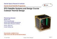
provides with necessary precautions by itsdesign.4. HARDWARE TESTSSatellites have to undergo a range of criticaltests in order to verify their expectedfunction in space. Successful tests add to thereliability of the system and reduce risks offailures. In particular for spacecrafts that relyon COTS devices, it becomes obvious thatextensive testing would be required. Yet,testing is time and money consuming andtherefore a trade-off between reliability andthose factors has to be done.Recommended test types for CubeSatsatellites can be found in ECCS documents[5], [6]:• Structural (shock, vibration, acoustic,load)• Thermal (cycling, vacuum)• Radiation (Total Dose, SEE)All those tests aim to simulate the environmentalconditions in orbit as close to realityas possible and to verify their functionality.Universities, which possess or have access tofacilities to conduct those tests, are clearlyadvised to make intensive use of them. Alesson learned by other CubeSat groups is tospend more time on test than ondevelopment (which does not imply thatdevelopment time should come too short).The <strong>FH</strong> <strong>Aachen</strong> owns a small vacuumchamber with an interior volume of about 35liter. Due to the small dimensions of theCubeSat, the entire satellite will fit into thechamber. Prior to the mechanical integrationof parts into the subsystems, they willundergo those vacuum tests. In particular thesun sensors and the camera are testedobligatory. By doing so, risks due tooutgassing or burst can be avoideddrastically.The chamber and the mounting plates aremade of stainless steal. The evacuation isdone using a three-stage pump system whichachieves a pressure of 10 -5 bar. On one sideof the T-shaped chamber there is an aperturecovered by quartz glass to allow viewing ofthe specimen inside. It is also used forexample to throw light upon the sun sensorswith a xenon lamp, which has spectralcharacteristics similar to that of the sun.Via a couple of access pins, the sampleinside the chamber can be supplied withelectrical power and simultaneously thegenerated data can be logged and evaluatedreal-time at a standard personal computerthat runs LabView.5. CONCLUSIONAs stated in this paper, picosatellites (such asthe CubeSats) are exposing a lot ofchallenges to the developing students. As aresponse new methods and concepts areengineered from ground up in order to meetthe specific stringent requirements of such atiny satellite.So far all CubeSat projects have in commonto make use of a major proportion of COTScomponents instead of expensive spaceproofedparts. Intensive ground testing aimsto reduce the thereby introduced risks. In theend, only successful missions in orbit canfinally clear if assumptions about reliabilitywere correct.As all CubeSat groups (and in particular thenewer ones) are facing the problematic ofselecting appropriative COTS componentsfor their design it would be a big relief ifthey could turn to documentations and testresults from other groups. Then a databasecan be established that encompasses allalready used devices together withrecommendations, test proceedings and theiroperational status in space.A constructive result of this practice wouldbe that future CubeSat missions become
more reliable, thus more attention andinvestment can be spent on the payload itselfand its utilization.6. REFERENCES[1] www.raumfahrt.fh-aachen.de[2] Calpoly and Stanford University.(2003). CUBESAT DesignSpecifications Document, RevisionVIII. http://cubesat.calpoly.edu/[3] Pederson, M. et al., Linear Two-AxisMOEMS Sun Sensor and the needfor MEMS in space. InternationalAstronautical Congress, Bremen,Germany, 2003[4] DLR GSOC's Space FlightTechnology Departmenthttp://www.weblab.dlr.de/rbrt/[5] ECCS-E-10-03A Testing. (2002).ESA/ESTEC. www.ecss.nl[6] ECCS-E-10-04A SpaceEnvironment. (2002). ESA/ESTEC.www.ecss.nl