Gate-dependent spin-orbit coupling in multi-electron car - Niels Bohr ...
Gate-dependent spin-orbit coupling in multi-electron car - Niels Bohr ...
Gate-dependent spin-orbit coupling in multi-electron car - Niels Bohr ...

Create successful ePaper yourself
Turn your PDF publications into a flip-book with our unique Google optimized e-Paper software.
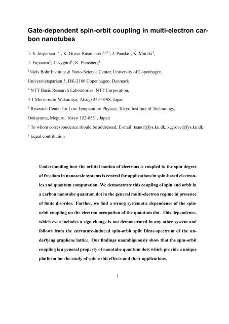
<strong>Gate</strong>-<strong>dependent</strong> <strong>sp<strong>in</strong></strong>-<strong>orbit</strong> <strong>coupl<strong>in</strong>g</strong> <strong>in</strong> <strong>multi</strong>-<strong>electron</strong> <strong>car</strong>bon<br />
nanotubes<br />
T. S. Jespersen 1∗† , K. Grove-Rasmussen 1,2∗† , J. Paaske 1 , K. Muraki 2 ,<br />
T. Fujisawa 3 , J. Nygård 1 , K. Flensberg 1 .<br />
1 <strong>Niels</strong> <strong>Bohr</strong> Institute & Nano-Science Center, University of Copenhagen,<br />
Universitetsparken 5, DK-2100 Copenhagen, Denmark<br />
2 NTT Basic Research Laboratories, NTT Corporation,<br />
3-1 Mor<strong>in</strong>osato-Wakamiya, Atsugi 243-0198, Japan<br />
3 Research Center for Low Temperature Physics, Tokyo Institute of Technology,<br />
Ookayama, Meguro, Tokyo 152-8551, Japan<br />
∗ To whom correspondence should be addressed; E-mail: tsand@fys.ku.dk, k grove@fys.ku.dk<br />
† Equal contribution<br />
Understand<strong>in</strong>g how the <strong>orbit</strong>al motion of <strong>electron</strong>s is coupled to the <strong>sp<strong>in</strong></strong> degree<br />
of freedom <strong>in</strong> nanoscale systems is central for applications <strong>in</strong> <strong>sp<strong>in</strong></strong>-based <strong>electron</strong>ics<br />
and quantum computation. We demonstrate this <strong>coupl<strong>in</strong>g</strong> of <strong>sp<strong>in</strong></strong> and <strong>orbit</strong> <strong>in</strong><br />
a <strong>car</strong>bon nanotube quantum dot <strong>in</strong> the general <strong>multi</strong>-<strong>electron</strong> regime <strong>in</strong> presence<br />
of f<strong>in</strong>ite disorder. Further, we f<strong>in</strong>d a strong systematic dependence of the <strong>sp<strong>in</strong></strong><strong>orbit</strong><br />
<strong>coupl<strong>in</strong>g</strong> on the <strong>electron</strong> occupation of the quantum dot. This dependence,<br />
which even <strong>in</strong>cludes a sign change is not demonstrated <strong>in</strong> any other system and<br />
follows from the curvature-<strong>in</strong>duced <strong>sp<strong>in</strong></strong>-<strong>orbit</strong> split Dirac-spectrum of the underly<strong>in</strong>g<br />
graphene lattice. Our f<strong>in</strong>d<strong>in</strong>gs unambiguously show that the <strong>sp<strong>in</strong></strong>-<strong>orbit</strong><br />
<strong>coupl<strong>in</strong>g</strong> is a general property of nanotube quantum dots which provide a unique<br />
platform for the study of <strong>sp<strong>in</strong></strong>-<strong>orbit</strong> effects and their applications.<br />
1
The <strong>in</strong>teraction of the <strong>sp<strong>in</strong></strong> of <strong>electron</strong>s with their <strong>orbit</strong>al motion has become a focus of attention<br />
<strong>in</strong> quantum dot research. On the one hand, this <strong>sp<strong>in</strong></strong>-<strong>orbit</strong> <strong>in</strong>teraction (SOI) provides a route<br />
for <strong>sp<strong>in</strong></strong> decoherence, which is unwanted for purposes of quantum computation 1–3 . On the other<br />
hand, if properly controlled, the SOI can be utilized as a means of electrically manipulat<strong>in</strong>g the<br />
<strong>sp<strong>in</strong></strong> degree of freedom 4–7 .<br />
In this context, <strong>car</strong>bon nanotubes provide a number of attractive features, <strong>in</strong>clud<strong>in</strong>g large<br />
conf<strong>in</strong>ement energies, nearly nuclear-<strong>sp<strong>in</strong></strong>-free environment, and, most importantly, the details of<br />
the energy level structure is theoretically well understood and modeled, as well as experimentally<br />
highly reproducible. Remarkably, the SOI <strong>in</strong> nanotubes was largely overlooked <strong>in</strong> the first two<br />
decades of nanotube research and was only recently demonstrated by Kuemmeth et al. for the special<br />
case of a s<strong>in</strong>gle <strong>car</strong>rier <strong>in</strong> ultra-clean CNT quantum dots 3, 8, 9 . Except for these reports, the SOI<br />
<strong>in</strong> nanotubes is experimentally unexplored. Theoretically, the focus has exclusively been on the<br />
SOI-modified band structure of disorder-free nanotubes 10–14 . Therefore, two important questions<br />
rema<strong>in</strong>: how the effective SOI depends on <strong>electron</strong> fill<strong>in</strong>g and how it appears <strong>in</strong> the general case of<br />
quantum dots subject to disorder. Here we answer these two questions.<br />
Firstly, by low-temperature <strong>electron</strong> transport we demonstrate the presence of a significant SOI<br />
<strong>in</strong> a disordered CNT quantum dot hold<strong>in</strong>g hundreds of <strong>electron</strong>s. We identify and analyze the<br />
role of SOI <strong>in</strong> the energy spectrum for one, two, and three <strong>electron</strong>s <strong>in</strong> the four-fold degenerate<br />
CNT <strong>electron</strong>ic shells, thus describ<strong>in</strong>g shells at any <strong>electron</strong> fill<strong>in</strong>g. By rotat<strong>in</strong>g the sample, we<br />
present for the first time spectroscopy of the same charge-states for magnetic fields both parallel<br />
and perpendicular to the nanotube axis, thus controll<strong>in</strong>g the <strong>coupl<strong>in</strong>g</strong> to the <strong>orbit</strong>al magnetic<br />
moment. Remarkably, a s<strong>in</strong>gle-<strong>electron</strong> model tak<strong>in</strong>g <strong>in</strong>to account both SOI and disorder quantitatively<br />
describes all essential details of the <strong>multi</strong>-<strong>electron</strong> quantum dot spectra. Secondly, by<br />
chang<strong>in</strong>g the <strong>electron</strong> occupancy we are able to tune the effective SOI and even reverse its sign<br />
<strong>in</strong> accordance with the expected curvature-<strong>in</strong>duced <strong>sp<strong>in</strong></strong>-<strong>orbit</strong> splitt<strong>in</strong>g of the underly<strong>in</strong>g graphene<br />
Dirac spectrum 1, 11–14 . Such systematic dependence has not been demonstrated <strong>in</strong> any other ma-<br />
2
terial system and may enable a new range of <strong>sp<strong>in</strong></strong>-<strong>orbit</strong> related applications. This microscopic<br />
understand<strong>in</strong>g and detailed model<strong>in</strong>g is <strong>in</strong> stark contrasts to situations encountered <strong>in</strong> alternative<br />
strong-SOI quantum-dot materials, such as InAs or InSb nanowires, where the effective SOI arises<br />
from bulk crystal effects comb<strong>in</strong>ed with unknown contributions from surface effects, stra<strong>in</strong> and<br />
crystal defects 15 . These systems often exhibit semi-random fluctuations of, e.g., the g-factor as<br />
s<strong>in</strong>gle <strong>electron</strong>s are added 16, 17 . Thus, beyond fundamental <strong>in</strong>terest and the prospect of realiz<strong>in</strong>g recent<br />
proposals of SOI-<strong>in</strong>duced <strong>sp<strong>in</strong></strong> control <strong>in</strong> CNTs 1, 18 , our f<strong>in</strong>d<strong>in</strong>gs pave the way for new designs<br />
of experiments utiliz<strong>in</strong>g the SOI <strong>in</strong> quantum dots.<br />
Zero-field splitt<strong>in</strong>g of the four-fold degeneracy<br />
Our experimental setup is presented <strong>in</strong> Fig. 1a. We fabricate devices of s<strong>in</strong>gle-wall CNTs on highly<br />
doped Si substrates capped with an <strong>in</strong>sulat<strong>in</strong>g layer of SiO 2 (see Methods section). The size of the<br />
quantum dots is def<strong>in</strong>ed by the contact separation (400 nm) and the electrical properties are <strong>in</strong>vestigated<br />
<strong>in</strong> a voltage biased two-term<strong>in</strong>al configuration apply<strong>in</strong>g a voltage V sd between source-dra<strong>in</strong><br />
contacts and measur<strong>in</strong>g the result<strong>in</strong>g current I. The differential conductance dI/dV sd is measured<br />
by standard lock-<strong>in</strong> techniques. When biased with a voltage V g , the Si substrate acts as an electrostatic<br />
gate controll<strong>in</strong>g the <strong>electron</strong> occupancy of the dot. The devices are measured at T = 100 mK<br />
<strong>in</strong> a 3 He/ 4 He dilution refrigerator, fitted with a piezo-rotator allow<strong>in</strong>g <strong>in</strong>-plane rotations of the device<br />
<strong>in</strong> magnetic fields up to 9 T.<br />
Figure 1b shows a typical measurement of dI/dV sd vs. V sd and V g <strong>in</strong> the <strong>multi</strong>-<strong>electron</strong><br />
regime of a small-band-gap semiconduct<strong>in</strong>g nanotube. The pattern of diamond-shaped regions of<br />
low conductance is expected for a quantum dot <strong>in</strong> the Coulomb blockade regime and with<strong>in</strong> each<br />
diamond the quantum dot hosts a fixed number of <strong>electron</strong>s N, <strong>in</strong>creas<strong>in</strong>g one-by-one with <strong>in</strong>creas<strong>in</strong>g<br />
V g . The energy E add , required for add<strong>in</strong>g a s<strong>in</strong>gle <strong>electron</strong> appears as the diamond heights<br />
3
and has been extracted <strong>in</strong> Fig. 1c. The four-<strong>electron</strong> periodicity clearly observed <strong>in</strong> Fig. 1b and c<br />
reflects the near four-fold degeneracy <strong>in</strong> the nanotube energy spectrum 19, 20 ; one factor of 2 from<br />
the <strong>in</strong>tr<strong>in</strong>sic <strong>sp<strong>in</strong></strong> (↑, ↓) and one factor of 2 from the so-called iso<strong>sp<strong>in</strong></strong> (K, K ′ ) that stems from the<br />
rotational symmetry of the nanotube - <strong>electron</strong>s <strong>orbit</strong> the CNT <strong>in</strong> a clockwise or anticlockwise<br />
direction. As is generally observed 19–23 , the addition energy for the second <strong>electron</strong> <strong>in</strong> each quartet<br />
(yellow <strong>in</strong> Fig. 1c) exceeds those for one and three. This was previously <strong>in</strong>terpreted as a result<br />
of disorder-<strong>in</strong>duced <strong>coupl<strong>in</strong>g</strong> ∆ KK ′<br />
of the clockwise and anticlockwise states 21, 24 that splits the<br />
spectrum <strong>in</strong>to two <strong>sp<strong>in</strong></strong>-degenerate pairs of bond<strong>in</strong>g/antibond<strong>in</strong>g states separated by ∆ KK ′. As<br />
mentioned, Kuemmeth et al. showed recently that for the first <strong>electron</strong> <strong>in</strong> an ultra-clean suspended<br />
nanotube quantum dot, the splitt<strong>in</strong>g was <strong>in</strong>stead dom<strong>in</strong>ated by the <strong>sp<strong>in</strong></strong>-<strong>orbit</strong> <strong>coupl<strong>in</strong>g</strong>. The first<br />
question we address here is whether SOI also appears <strong>in</strong> the many-<strong>electron</strong> regime and how it may<br />
be modified or masked by disorder.<br />
Model<strong>in</strong>g <strong>sp<strong>in</strong></strong>-<strong>orbit</strong> <strong>coupl<strong>in</strong>g</strong> and disorder<br />
Perform<strong>in</strong>g level spectroscopy with a magnetic field B applied either parallel (B ‖ ) or perpendicular<br />
(B ⊥ ) to the nanotube axis proves to be a powerful tool to analyze the separate contributions from<br />
disorder and <strong>sp<strong>in</strong></strong>-<strong>orbit</strong> <strong>coupl<strong>in</strong>g</strong>. This is illustrated <strong>in</strong> Figs. 2a-d, which show calculated s<strong>in</strong>gleparticle<br />
energy level spectra for four limit<strong>in</strong>g comb<strong>in</strong>ations of ∆ KK ′<br />
and the effective <strong>sp<strong>in</strong></strong>-<strong>orbit</strong><br />
<strong>coupl<strong>in</strong>g</strong> ∆ SO (all limits are relevant for nanotube devices depend<strong>in</strong>g on the degree of disorder<br />
and CNT structure 13, 14 ; details of the model are provided <strong>in</strong> the Supplementary Information). In<br />
all cases a parallel field separates the four states <strong>in</strong>to pairs of <strong>in</strong>creas<strong>in</strong>g (K-like states) and decreas<strong>in</strong>g<br />
(K ′ -like states) energies. The magnitude of the shift is given by the <strong>orbit</strong>al g-factor g orb<br />
reflect<strong>in</strong>g the <strong>coupl<strong>in</strong>g</strong> of B ‖ to the <strong>orbit</strong>al magnetic moment caused by motion around the CNT 25 .<br />
Further, each pair exhibits a smaller <strong>in</strong>ternal splitt<strong>in</strong>g due to the Zeeman effect. Figure 2b shows<br />
4
the disorder <strong>in</strong>duced <strong>coupl<strong>in</strong>g</strong> of K and K ′ states result<strong>in</strong>g <strong>in</strong> an avoided cross<strong>in</strong>g at B ‖ = 0 and<br />
the zero-field splitt<strong>in</strong>g discussed above. In the opposite limit with SOI only (Fig. 2c), the zerofield<br />
spectrum is also split <strong>in</strong>to two doublets, but the field dependence is markedly different and<br />
no avoided cross<strong>in</strong>g appears. In the simplest picture, this behavior orig<strong>in</strong>ates from <strong>coupl<strong>in</strong>g</strong> of the<br />
<strong>electron</strong> <strong>sp<strong>in</strong></strong> to an effective magnetic field B SO = −(v × E)/c 2 experienced by the <strong>electron</strong> as<br />
it moves with velocity v <strong>in</strong> an electric field E. Here the speed of light, c, reflects the relativistic<br />
orig<strong>in</strong> of the effect. In nanotubes, the curvature of the graphene lattice generates an effective radial<br />
electric field, and s<strong>in</strong>ce the velocity is ma<strong>in</strong>ly circumferential (and opposite for K and K ′ ), B SO<br />
polarizes the <strong>sp<strong>in</strong></strong>s along the nanotube axis and favors parallel alignment of the <strong>sp<strong>in</strong></strong> and <strong>orbit</strong>al<br />
angular momentum. Thus, even <strong>in</strong> the absence of disorder, the spectrum splits <strong>in</strong>to two Kramers<br />
doublets (K ↓, K ′ ↑) and (K ↑, K ′ ↓) separated by ∆ SO . Interest<strong>in</strong>gly, s<strong>in</strong>ce a perpendicular field<br />
does not couple K and K ′ the doublets do not split along B ⊥ on the figure. As a consequence, the<br />
g-factor, when measured <strong>in</strong> a perpendicular field, will vary from zero when ∆ SO ≫ ∆ KK ′<br />
(Fig.<br />
2c) to 2 <strong>in</strong> the opposite limit (Fig. 2b).<br />
The f<strong>in</strong>al case, <strong>in</strong>clud<strong>in</strong>g both disorder and SOI, is of particular importance for the present<br />
study, and the calculated spectrum is displayed <strong>in</strong> Fig. 2d for ∆ KK ′<br />
> ∆ SO . Importantly, the<br />
effects of SOI are not masked despite the dom<strong>in</strong>at<strong>in</strong>g disorder: For parallel field, SOI rema<strong>in</strong>s responsible<br />
for an asymmetric splitt<strong>in</strong>g of the Kramers doublets (α, β) vs. (δ, γ), and the appearance<br />
of an additional degeneracy <strong>in</strong> the spectrum at f<strong>in</strong>ite field (δ and γ states). In a perpendicular field,<br />
the effect of SOI is to suppress the Zeeman splitt<strong>in</strong>g of the two doublets and s<strong>in</strong>ce the eigenstates<br />
of the SOI have <strong>sp<strong>in</strong></strong>s along the nanotube axis it couples the states with <strong>sp<strong>in</strong></strong>s polarized along B ⊥<br />
result<strong>in</strong>g <strong>in</strong> the avoided cross<strong>in</strong>g <strong>in</strong>dicated on the figure.<br />
5
Sp<strong>in</strong>-<strong>orbit</strong> <strong>in</strong>teraction revealed by spectroscopy<br />
With this <strong>in</strong> m<strong>in</strong>d we now focus on the quartet with 4N 0 ≈ 180 <strong>electron</strong>s highlighted <strong>in</strong> Fig. 1b<br />
and expanded <strong>in</strong> Fig. 3a. In order to <strong>in</strong>vestigate the level structure we perform cotunnel<strong>in</strong>g spectroscopy,<br />
as illustrated <strong>in</strong> the schematic Fig. 3b 26 : In Coulomb blockade, whenever e|V sd | matches<br />
the energy of a transition from the ground state α to an excited state (β, γ, δ), <strong>in</strong>elastic cotunnel<br />
processes, that leave the quantum dot <strong>in</strong> the excited state, become available for transport. This<br />
significantly <strong>in</strong>creases the current and gives rise to steps <strong>in</strong> the conductance. These appear as gate<strong>in</strong><strong>dependent</strong><br />
features <strong>in</strong> Fig. 3a (arrows) and are clearly seen <strong>in</strong> the <strong>in</strong>set show<strong>in</strong>g a trace through<br />
the center of the one-<strong>electron</strong> (4N 0 + 1) diamond along the dashed l<strong>in</strong>e. Thus follow<strong>in</strong>g the magnetic<br />
field dependence of this trace, as shown <strong>in</strong> Fig. 3c, maps out the level structure. The energies<br />
of the excitations are given by the <strong>in</strong>flection po<strong>in</strong>ts of the curve (i.e. peaks/dips of d 2 I/dV 2<br />
sd) 27 and<br />
the level evolution is therefore directly evident <strong>in</strong> Fig. 3d-i, which show color maps of the second<br />
derivative vs. V sd and B ⊥ , B ‖ for V g positioned <strong>in</strong> the center of the one, two, and three <strong>electron</strong><br />
charge states. As expla<strong>in</strong>ed below, the SOI is clearly expressed <strong>in</strong> all three spectra.<br />
Consider first the one-<strong>electron</strong> case: In a parallel field (Fig. 3d), the asymmetric splitt<strong>in</strong>g of<br />
the two doublets is evident (black vs. green arrows) and apply<strong>in</strong>g the field perpendicularly (Panel<br />
g), the SOI is directly expressed as the avoided cross<strong>in</strong>g <strong>in</strong>dicated on the figure. The measurement<br />
is <strong>in</strong> near-perfect agreement with the s<strong>in</strong>gle-particle excitation spectrum calculated by subtract<strong>in</strong>g<br />
the energies of Fig. 3b and shown by the solid l<strong>in</strong>es. The calculation depends on only three parameters:<br />
∆ SO = 0.15 meV set directly by the avoided cross<strong>in</strong>g, ∆ KK ′<br />
= 0.45 meV determ<strong>in</strong>ed<br />
from the zero-field splitt<strong>in</strong>g of the doublets (see Fig. 2d), and g orb = 5.7 set by the slopes of the<br />
excitation l<strong>in</strong>es from α to γ, δ <strong>in</strong> Panel d.<br />
Consider now the role of SOI for the doubly occupied CNT quartet. This situation is of particular<br />
importance for quantum computation as a paradigm for preparation of entangled states and<br />
a fundamental part of Pauli blockade <strong>in</strong> double quantum dots 28 . Figures 3e,h show the measured<br />
6
spectra <strong>in</strong> parallel and perpendicular fields. The model perfectly describes the measurement and<br />
now conta<strong>in</strong>s no free parameters s<strong>in</strong>ce these are fixed by one-<strong>electron</strong> measurement. Six states are<br />
expected: the ground state s<strong>in</strong>glet-like state ˜S 0 formed by the two <strong>electron</strong>s occupy<strong>in</strong>g the lowenergy<br />
Kramers doublet 29 , three triplet-like ˜T − , ˜T 0 , ˜T + and a s<strong>in</strong>glet-like state ˜S 1 , which all use<br />
one state from each doublet and the s<strong>in</strong>glet-like ˜S 2 with both <strong>electron</strong>s occupy<strong>in</strong>g the high-energy<br />
doublet. The ground state ˜S 0 does not appear directly <strong>in</strong> the measurement, but sets the orig<strong>in</strong> for<br />
the cotunnel<strong>in</strong>g excitations. The excitation to the high-energy ˜S 2 (dashed l<strong>in</strong>e) is absent <strong>in</strong> the<br />
experiment, s<strong>in</strong>ce it cannot be reached by promot<strong>in</strong>g only a s<strong>in</strong>gle <strong>electron</strong> from ˜S 0 . In Fig. 3h<br />
excitations to ˜T − and ˜T + are clearly observed, while ˜S 1 and ˜T 0 merge <strong>in</strong>to a s<strong>in</strong>gle high-<strong>in</strong>tensity<br />
peak show<strong>in</strong>g that any exchange splitt<strong>in</strong>g J is below the spectroscopic l<strong>in</strong>e width ≈ 100µeV 23 . In<br />
other quartets an exchange splitt<strong>in</strong>g is <strong>in</strong>deed observed (see Supplementary Information). In the<br />
two-<strong>electron</strong> spectra the SOI is directly expressed as the avoided cross<strong>in</strong>g at B ⊥ ≈ 4.5 T accompany<strong>in</strong>g<br />
the ˜S 0 ↔ ˜T − ground state transition 15, 30 . In quartets of yet stronger tunnel-<strong>coupl<strong>in</strong>g</strong> it is<br />
replaced by a s<strong>in</strong>glet-triplet Kondo resonance 31 (see Supplementary Information).<br />
F<strong>in</strong>ally, the spectrum of three <strong>electron</strong>s <strong>in</strong> the four-<strong>electron</strong> shell is equivalent to that of a<br />
s<strong>in</strong>gle hole <strong>in</strong> a full shell; at low fields the δ-state becomes the ground-state and γ the first excited<br />
state, while α and β then constitute the excited doublet. As seen by compar<strong>in</strong>g Fig. 2b and 2d<br />
SOI breaks the <strong>in</strong>tra-shell <strong>electron</strong>-hole symmetry of the nanotube spectrum. This is evident <strong>in</strong><br />
the experiment when compar<strong>in</strong>g Fig. 3d and 3f: In 3f, <strong>in</strong>creas<strong>in</strong>g B ‖ , the lowest excited state γ,<br />
barely separates from the ground state δ and at B ‖ = 1.1 T they cross aga<strong>in</strong>, caus<strong>in</strong>g a ground state<br />
transition. At the cross<strong>in</strong>g po<strong>in</strong>t, the <strong>sp<strong>in</strong></strong>-degenerate ground-state results <strong>in</strong> a zero-bias Kondo<br />
peak (see <strong>in</strong>set) 32 . Interest<strong>in</strong>gly, this degeneracy also forms the qubit proposed <strong>in</strong> Ref. 1. For the<br />
B ⊥ -dependence the one- and three-<strong>electron</strong> cases rema<strong>in</strong> identical and Fig. 3i exhibits aga<strong>in</strong> the<br />
SOI-<strong>in</strong>duced avoided cross<strong>in</strong>gs.<br />
7
<strong>Gate</strong>-<strong>dependent</strong> <strong>sp<strong>in</strong></strong>-<strong>orbit</strong> <strong>coupl<strong>in</strong>g</strong><br />
Hav<strong>in</strong>g established the presence of SOI <strong>in</strong> the general many-<strong>electron</strong> disordered quantum dot, we<br />
now focus on the dependence of ∆ SO on the quantum dot occupation. To this end, we have repeated<br />
the spectroscopy of Fig. 3 for a large number of CNT quartets and <strong>in</strong> each case extracted<br />
∆ SO by fitt<strong>in</strong>g to the s<strong>in</strong>gle-particle model (all underly<strong>in</strong>g data are presented <strong>in</strong> the Supplementary<br />
Information). Figure 4a shows the result as a function of V g . An overall decrease of ∆ SO is observed<br />
as <strong>electron</strong>s are added to the conduction band and, <strong>in</strong>terest<strong>in</strong>gly, a negative value is found<br />
<strong>in</strong> the valence band (i.e. SOI favor<strong>in</strong>g anti-parallel rather than parallel <strong>sp<strong>in</strong></strong> and <strong>orbit</strong>al angular<br />
momentum, thus effectively <strong>in</strong>terchang<strong>in</strong>g the one and three-<strong>electron</strong> spectra).<br />
The magnitude of ∆ SO is given by the <strong>sp<strong>in</strong></strong>-<strong>orbit</strong> splitt<strong>in</strong>g of the underly<strong>in</strong>g graphene band<br />
structure as we will now discuss.<br />
For flat graphene this splitt<strong>in</strong>g is very weak (∆ graphene<br />
SO<br />
1 µeV) 12 as it is second-order <strong>in</strong> the already weak atomic SOI of <strong>car</strong>bon ∆ C SO ∼ 8 meV. In<br />
nanotubes, however, the curvature <strong>in</strong>duces a <strong>coupl<strong>in</strong>g</strong> between the π- and σ-bands and generates<br />
a curvature-<strong>in</strong>duced <strong>sp<strong>in</strong></strong>-<strong>orbit</strong> splitt<strong>in</strong>g, which is first order <strong>in</strong> the atomic SOI and thus greatly<br />
enhances ∆ SO . Around a Dirac-po<strong>in</strong>t of the Brillou<strong>in</strong> zone (e.g. K) the graphene band structure<br />
appears as on Fig. 4b 11–14 : The <strong>sp<strong>in</strong></strong>-up and <strong>sp<strong>in</strong></strong>-down Dirac cones are split by SOI both <strong>in</strong> energy<br />
and along k ⊥ , the momentum <strong>in</strong> the circumferential direction of the CNT. The schematic also<br />
highlights the CNT band structure (Fig. 4a upper <strong>in</strong>set) obta<strong>in</strong>ed by impos<strong>in</strong>g periodic boundary<br />
conditions on k ⊥ . In a f<strong>in</strong>ite-length CNT quantum dot also the wavevector along the nanotube axis,<br />
k ‖ , is quantized, and lett<strong>in</strong>g ɛ N denote the energy of the N th longitud<strong>in</strong>al mode the effective SOI<br />
for a small-gap CNT becomes<br />
∆ SO,± = E↑ K − E↓ K (1)<br />
√<br />
√<br />
= 2∆ 0 SO ± (∆ g + ∆ 1 SO) 2 + ɛ 2 N ∓ (∆ g − ∆ 1 SO) 2 + ɛ 2 N.<br />
Here the upper(lower) sign refers to the conduction(valence) band, ∆ g is the curvature <strong>in</strong>duced<br />
energy gap 33, 34 , and the two terms ∆ 0 SO and ∆ 1 SO are the band structure <strong>sp<strong>in</strong></strong>-<strong>orbit</strong> parameters due to<br />
8<br />
∼
curvature 11–14 . The separate contributions of the two terms are illustrated <strong>in</strong> the lower <strong>in</strong>set to Fig.<br />
4a. ∆ 1 SO was found already <strong>in</strong> the work of Ando 10 and accounts for the k ⊥ -separation of the Diraccones<br />
<strong>in</strong> Fig. 4b. For the CNT band structure this term acts equivalently to an Aharonov-Bohm flux<br />
from a parallel <strong>sp<strong>in</strong></strong>-<strong>dependent</strong> magnetic field, which changes the quantization conditions <strong>in</strong> the k ⊥ -<br />
direction. Characteristically, its contribution to ∆ SO decreases with the number of <strong>electron</strong>s <strong>in</strong> the<br />
dot (ɛ N ) and reverses sign for the valence band. This contrasts the ɛ N -<strong>in</strong><strong>dependent</strong> contribution<br />
from the recently predicted ∆ 0 SO-term 12–14 , which acts as an effective valley-<strong>dependent</strong> Zeeman<br />
term and accounts for the energy splitt<strong>in</strong>g of the Dirac-cones <strong>in</strong> Fig. 4b. For the nanotube studied<br />
<strong>in</strong> Kuemmeth et al. 8 ∆ SO has the same sign for <strong>electron</strong>s and holes, i.e., |∆ 0 SO| > |∆ 1 SO|. In our<br />
case, the negative values measured <strong>in</strong> the valence band demonstrate the opposite limit |∆ 0 SO| <<br />
|∆ 1 SO|. Thus, the measured gate-dependence of ∆ SO agrees with the <strong>sp<strong>in</strong></strong>-<strong>orbit</strong> splitt<strong>in</strong>g of the<br />
graphene Dirac spectrum caused by the curvature of the nanotube, and fitt<strong>in</strong>g to Eq. 1 (Fig. 4a,<br />
dashed l<strong>in</strong>e) yields ∆ 0 SO = 10 ± 10 µeV and ∆ 1 SO = 220 ± 25 µeV 35 . Band structure models<br />
relate these parameters to the structure of the nanotube 12–14 : ∆ 0 SO = λ 0 ∆ C SO∆ g D and ∆ 1 SO =<br />
λ 1 ∆ C SO/D, where D is the nanotube diameter and λ 1,2 constants that depend on the CNT class<br />
(semiconduct<strong>in</strong>g, small-band-gap). Typically CVD-grown s<strong>in</strong>gle wall CNTs have diameters <strong>in</strong><br />
the range 1-3 nm, while obta<strong>in</strong><strong>in</strong>g D from the measured values of g 36 orb gives D ≈ 6 nm. Thus<br />
tak<strong>in</strong>g D = 1-6 nm we estimate λ 1 = 0.03-0.17 nm and λ 0 = 0.7-4 · 10 −6 (nm · meV) −1 . While<br />
λ 1 is consistent with the value quoted <strong>in</strong> the theoretical literature (0.095 nm) 14 , the calculated λ 0<br />
value −4·10 −3 (nm · meV) −1 does not match the experiment and similar deviations appear 14 when<br />
compar<strong>in</strong>g the theory to the SOI values measured <strong>in</strong> Ref. 8. The orig<strong>in</strong> of this discrepancy rema<strong>in</strong>s<br />
unknown, and further work on SOI <strong>in</strong> nanotubes with known chirality is needed to make further<br />
progress.<br />
9
Methods<br />
The devices are made on a highly doped Silicon wafer term<strong>in</strong>ated by 500 nm of SiO 2 . Alignment<br />
marks (Cr, 70 nm) are def<strong>in</strong>ed by <strong>electron</strong> beam lithography prior to deposition of catalyst<br />
islands made of Iron nitrate (Fe(NO 3 ) 3 ), Molybdenum acetate and Alum<strong>in</strong>a support particles 37 .<br />
The sample is then transferred to a furnace, where s<strong>in</strong>gle wall <strong>car</strong>bon nanotubes are grown by<br />
chemical vapor deposition at 850-900 ◦ C <strong>in</strong> an atmosphere of hydrogen, argon and methane gases.<br />
Pairs of electrodes consist<strong>in</strong>g of Au/Pd (40/10 nm) spaced by 400 nm are fabricated alongside<br />
the catalyst islands by standard <strong>electron</strong> beam lithography techniques.<br />
F<strong>in</strong>ally, bond<strong>in</strong>g pads<br />
(Au/Cr 150/10 nm) are made by optical lithography and the devices are screened by room- and<br />
low-temperature measurements.<br />
We measured the sample <strong>in</strong> an Oxford dilution refrigerator fitted with an Attocube ANRv51<br />
piezo rotator which allows high precision <strong>in</strong>-plane rotation of the sample <strong>in</strong> large magnetic fields.<br />
The rotator provides resistive feedback of the actual position measured by lock-<strong>in</strong> techniques. For<br />
electrical filter<strong>in</strong>g, room-temperature π-filters and low-temperature Thermocoax are used. The<br />
base temperature of the modified refrigerator is around 100 mK. The CNT measurement setup<br />
consists of a National Instrument digital to analog <strong>car</strong>d, custom made optically coupled amplifiers,<br />
a DL Instruments 1211 current to voltage amplifier and a Pr<strong>in</strong>ceton Applied Research 5210 Lock<strong>in</strong><br />
amplifier. Standard dc and lock-<strong>in</strong> techniques have been used to measure current and differential<br />
conductance dI/dV sd while d 2 I/dV 2<br />
sd is obta<strong>in</strong>ed numerically.<br />
10
References and Notes<br />
1. Bulaev, D., Trauzettel, B. & Loss, D. Sp<strong>in</strong>-<strong>orbit</strong> <strong>in</strong>teraction and anomalous <strong>sp<strong>in</strong></strong> relaxation <strong>in</strong><br />
<strong>car</strong>bon nanotube quantum dots. Phys. Rev. B 77, 235301 (2008).<br />
2. Fischer, J. & Loss, D. Deal<strong>in</strong>g with decoherence. Science 324, 1277–1278 (2009).<br />
3. Churchill, H. et al. Electron-nuclear <strong>in</strong>teraction <strong>in</strong> c-13 nanotube double quantum dots. Nat.<br />
Phys. 5, 321 – 326 (2009).<br />
4. Fl<strong>in</strong>dt, C., Sørensen, A. & Flensberg, K. Sp<strong>in</strong>-<strong>orbit</strong> mediated control of <strong>sp<strong>in</strong></strong> qubits.<br />
Phys. Rev. Lett. 97, 240501 (2006).<br />
5. Trif, M., Golovach, V. & Loss, D. Sp<strong>in</strong>-<strong>sp<strong>in</strong></strong> <strong>coupl<strong>in</strong>g</strong> <strong>in</strong> electrostatically coupled quantum<br />
dots. Phys. Rev. B 75, 085307 (2007).<br />
6. Nowack, K., Koppens, F., Nazarov, Y. & Vandersypen, L. Coherent control of a s<strong>in</strong>gle <strong>electron</strong><br />
<strong>sp<strong>in</strong></strong> with electric fields. Science 318, 1430 – 1433 (2007).<br />
7. Pfund, A., Shorubalko, I., Enssl<strong>in</strong>, K. & Leturcq, R. Suppression of <strong>sp<strong>in</strong></strong> relaxation <strong>in</strong> an <strong>in</strong>as<br />
nanowire double quantum dot. Phys. Rev. Lett. 99, 036801 (2007).<br />
8. Kuemmeth, F., Ilani, S., Ralph, D. & McEuen, P. Coupl<strong>in</strong>g of <strong>sp<strong>in</strong></strong> and <strong>orbit</strong>al motion of<br />
<strong>electron</strong>s <strong>in</strong> <strong>car</strong>bon nanotubes. Nature 452, 448 – 452 (2008).<br />
9. Kuemmeth, F., Churchill, H., Herr<strong>in</strong>g, P. & Marcus, C. Carbon nanotubes for coherent <strong>sp<strong>in</strong></strong>tronics.<br />
Mat. Today 13, 18–26 (2010).<br />
10. Ando, T. Sp<strong>in</strong>-<strong>orbit</strong> <strong>in</strong>teraction <strong>in</strong> <strong>car</strong>bon nanotubes. J. Phys. Soc. Jpn. 69, 1757 – 1763<br />
(2000).<br />
11. Chico, L., Lopez-Sancho, M. & Munoz, M. Sp<strong>in</strong> splitt<strong>in</strong>g <strong>in</strong>duced by <strong>sp<strong>in</strong></strong>-<strong>orbit</strong> <strong>in</strong>teraction <strong>in</strong><br />
chiral nanotubes. Phys. Rev. Lett. 93, 176402 (2004).<br />
11
12. Huertas-Hernando, D., Gu<strong>in</strong>ea, F. & Brataas, A. Sp<strong>in</strong>-<strong>orbit</strong> <strong>coupl<strong>in</strong>g</strong> <strong>in</strong> curved graphene,<br />
fullerenes, nanotubes, and nanotube caps. Phys. Rev. B 74, 155426 (2006).<br />
13. Jeong, J. & Lee, H. Curvature-enhanced <strong>sp<strong>in</strong></strong>-<strong>orbit</strong> <strong>coupl<strong>in</strong>g</strong> <strong>in</strong> a <strong>car</strong>bon nanotube. Phys. Rev. B<br />
80, 075409 (2009).<br />
14. Izumida, W., Sato, K. & Saito, R. Sp<strong>in</strong>-<strong>orbit</strong> <strong>in</strong>teraction <strong>in</strong> s<strong>in</strong>gle wall <strong>car</strong>bon nanotubes:<br />
Symmetry adapted tight-b<strong>in</strong>d<strong>in</strong>g calculation and effective model analysis. J. Phys. Soc. Jpn.<br />
78, 074707 (2009).<br />
15. Fasth, C., Fuhrer, A., Samuelson, L., Golovach, V. & Loss, D. Direct measurement of the<br />
<strong>sp<strong>in</strong></strong>-<strong>orbit</strong> <strong>in</strong>teraction <strong>in</strong> a two-<strong>electron</strong> <strong>in</strong>as nanowire quantum dot. Phys. Rev. Lett. 98, 266801<br />
(2007).<br />
16. Csonka, S. et al. Giant fluctuations and gate control of the g-factor <strong>in</strong> <strong>in</strong>as nanowire quantum<br />
dots. Nano Lett. 8, 3932–3935 (2008).<br />
17. Nilsson, H. et al. Giant, level-<strong>dependent</strong> g factors <strong>in</strong> <strong>in</strong>sb nanowire quantum dots. Nano Lett.<br />
9, 3151–3156 (2009).<br />
18. Flensberg, K. & Marcus, C. Bends <strong>in</strong> nanotubes allow electric <strong>sp<strong>in</strong></strong> control and <strong>coupl<strong>in</strong>g</strong>.<br />
Phys. Rev. B 81, 195418 (2010).<br />
19. Liang, W., Bockrath, M. & Park, H. Shell fill<strong>in</strong>g and exchange <strong>coupl<strong>in</strong>g</strong> <strong>in</strong> metallic s<strong>in</strong>glewalled<br />
<strong>car</strong>bon nanotubes. Phys. Rev. Lett. 88, 126801 (2002).<br />
20. Cobden, D. & Nygard, J. Shell fill<strong>in</strong>g <strong>in</strong> closed s<strong>in</strong>gle-wall <strong>car</strong>bon nanotube quantum dots.<br />
Phys. Rev. Lett. 89, 046803 (2002).<br />
21. Jarillo-Herrero, P. et al. Electronic transport spectroscopy of <strong>car</strong>bon nanotubes <strong>in</strong> a magnetic<br />
field. Phys. Rev. Lett. 94, 156802 (2005).<br />
12
22. Makarovski, A., An, L., Liu, J. & F<strong>in</strong>kelste<strong>in</strong>, G. Persistent <strong>orbit</strong>al degeneracy <strong>in</strong> <strong>car</strong>bon<br />
nanotubes. Phys. Rev. B 74, 155431 (2006).<br />
23. Moriyama, S., Fuse, T., Suzuki, M., Aoyagi, Y. & Ishibashi, K. Four-<strong>electron</strong> shell structures<br />
and an <strong>in</strong>teract<strong>in</strong>g two-<strong>electron</strong> system <strong>in</strong> <strong>car</strong>bon-nanotube quantum dots. Phys. Rev. Lett. 94,<br />
186806 (2005).<br />
24. Oreg, Y., Byczuk, K. & Halper<strong>in</strong>, B. Sp<strong>in</strong> configurations of a <strong>car</strong>bon nanotube <strong>in</strong> a nonuniform<br />
externalpotential. Phys. Rev. Lett. 85, 365–368 (2000).<br />
25. M<strong>in</strong>ot, E., Yaish, Y., Sazonova, V. & Mceuen, P. Determ<strong>in</strong>ation of <strong>electron</strong> <strong>orbit</strong>al magnetic<br />
moments <strong>in</strong> <strong>car</strong>bon nanotubes. Nature 428, 536 – 539 (2004).<br />
26. De Franceschi, S. et al. Electron cotunnel<strong>in</strong>g <strong>in</strong> a semiconductor quantum dot. Phys. Rev. Lett.<br />
86, 878–881 (2001).<br />
27. Paaske, J. et al. Non-equilibrium s<strong>in</strong>glet-triplet kondo effect <strong>in</strong> <strong>car</strong>bon nanotubes. Nat. Phys.<br />
2, 460–464 (2006).<br />
28. Hanson, R., Kouwenhoven, L., Petta, J., Tarucha, S. & Vandersypen, L. Sp<strong>in</strong>s <strong>in</strong> few-<strong>electron</strong><br />
quantum dots. Rev. Mod. Phys. 79, 1217–1265 (2007).<br />
29. The states are not the conventional <strong>sp<strong>in</strong></strong> s<strong>in</strong>glets and triplets as the they are modified by SOI<br />
as emphasized by the tildes.<br />
30. From the high-field ground state ˜T − , excitations to ˜S 2 are actually allowed, however, the ˜S 0 ↔<br />
˜T − and ˜S 2<br />
↔ ˜T + avoided cross<strong>in</strong>gs occur simultaneously and as ˜T − to ˜T + excitations are<br />
forbidden the dashed l<strong>in</strong>e rema<strong>in</strong>s unseen <strong>in</strong> the experiment.<br />
31. Nygard, J., Cobden, D. & L<strong>in</strong>delof, P. Kondo physics <strong>in</strong> <strong>car</strong>bon nanotubes. Nature 408,<br />
342–346 (2000).<br />
13
32. Galp<strong>in</strong>, M., Jayatilaka, F., Logan, D. & Anders, F. Interplay between kondo physics and<br />
<strong>sp<strong>in</strong></strong>-<strong>orbit</strong> <strong>coupl<strong>in</strong>g</strong> <strong>in</strong> <strong>car</strong>bon nanotube quantum dots. Phys. Rev. B 81, 075437 (2010).<br />
33. Kane, C. & Mele, E. Size, shape, and low energy <strong>electron</strong>ic structure of <strong>car</strong>bon nanotubes.<br />
Phys. Rev. Lett. 78, 1932–1935 (1997).<br />
34. Kle<strong>in</strong>er, A. & Eggert, S. Band gaps of primary metallic <strong>car</strong>bon nanotubes. Phys. Rev. B 63,<br />
073408 (2001).<br />
35. The band-gap of the device E g ≈ 30 meV is measured directly as a large Coulomb diamond<br />
at V g ≈ 1 V and ɛ N ≈ 25 meV/V × V g is estimated from the level spac<strong>in</strong>g ∆E ≈ 3 meV and<br />
≈ 8 shells/V .<br />
36. With<strong>in</strong> the present theory the <strong>orbit</strong>al g-factor depends on <strong>electron</strong> fill<strong>in</strong>g g orb ≈<br />
(ev F D/2µ B )/ √ 1 + (ɛ n /∆ g ) 2 <strong>in</strong> agreement with the measurements (see SOM).<br />
37. Kong, J., Soh, H., Cassell, A., Quate, C. & Dai, H. Synthesis of <strong>in</strong>dividual s<strong>in</strong>gle-walled<br />
<strong>car</strong>bon nanotubes on patterned silicon wafers. Nature 395, 878–881 (1998).<br />
Acknowledgements<br />
We thank P. E. L<strong>in</strong>delof, J. Myg<strong>in</strong>d, H.I. Jørgensen, C.M. Marcus, and F. Kuemmeth for discussions<br />
and experimental support. T.S.J. acknowledges the Carlsberg Foundation and Lundbeck<br />
Foundation for f<strong>in</strong>ancial support. K.G.R. K.F. J.N. acknowledges The Danish Research Council<br />
and University of Copenhagen Center of Excellence.<br />
Author contributions<br />
T.S.J. and K.G.R. performed the measurements, analyzed the data and wrote the paper. T.S.J.<br />
designed the rotat<strong>in</strong>g sample stage. K.G.R. made the sample. K.M., T.F. and J.N. participated <strong>in</strong><br />
14
discussions and writ<strong>in</strong>g the paper. J.P. and K.F. developed the theory and guided the experiment.<br />
15
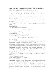
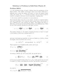
Figure 1<br />
Four-fold periodic nanotube spectrum. a, Schematic illustration of the device<br />
and setup. CNT quantum dots are measured at T = 100 mK <strong>in</strong> a standard two-term<strong>in</strong>al<br />
configuration <strong>in</strong> a cryostat modified to enable measurements <strong>in</strong> a high magnetic field at<br />
arbitrary <strong>in</strong>-plane angles θ to the CNT axis. b, Typical measurement of the differential<br />
conductance dI/dV sd vs. source-dra<strong>in</strong> bias V sd and gate voltage V g for a <strong>multi</strong>-<strong>electron</strong><br />
CNT quantum dot. c, Addition energy as a function of V g . In b and c the characteristic<br />
fill<strong>in</strong>g of four-<strong>electron</strong> shells is clearly seen.<br />
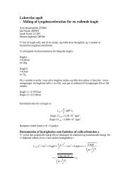
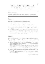
Figure 2<br />
Role of <strong>sp<strong>in</strong></strong>-<strong>orbit</strong> <strong>in</strong>teraction and disorder for the nanotube energy spectrum.<br />
Calculated s<strong>in</strong>gle-particle energy spectrum as a function of magnetic field applied perpendicular<br />
(B ⊥ ) and parallel (B ‖ ) to the CNT axis <strong>in</strong> the limit<strong>in</strong>g cases of neither SOI nor<br />
disorder a, disorder alone b, SOI alone c, and the two comb<strong>in</strong>ed ∆ KK ′ > ∆ SO > 0 d.<br />
Depend<strong>in</strong>g on the CNT type, <strong>electron</strong> fill<strong>in</strong>g and degree of disorder, all four situations can<br />
occur.<br />
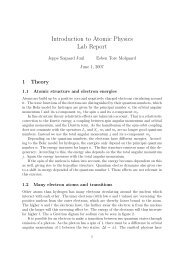
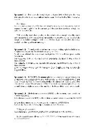
Figure 3<br />
Sp<strong>in</strong>-<strong>orbit</strong> <strong>in</strong>teraction <strong>in</strong> a disordered <strong>multi</strong>-<strong>electron</strong> nanotube quantum dot.<br />
a, Measurement of dI/dV sd vs. V sd and V g correspond<strong>in</strong>g to the consecutive addition of<br />
four <strong>electron</strong>s to an empty shell (<strong>in</strong>dicated on Fig. 1b). A strong tunnel <strong>coupl<strong>in</strong>g</strong> results<br />
<strong>in</strong> significant cotunnel<strong>in</strong>g which is evident as horizontal l<strong>in</strong>es truncat<strong>in</strong>g the diamonds<br />
(arrows). The black trace shows a cut along the dashed l<strong>in</strong>e. b, Schematic illustration<br />
of the relevant <strong>in</strong>elastic cotunnel<strong>in</strong>g processes. c, Traces along the dashed l<strong>in</strong>e <strong>in</strong> a for<br />
various B ‖ (red: B = 0, scale-bar: 0.1e 2 /h). d-f, The second derivative d 2 I/dV 2<br />
sd along the<br />
center of the N 0 + 1, N 0 + 2 and N 0 + 3 diamonds, respectively, as a function of a parallel<br />
magnetic field. Peaks/dips appear at <strong>in</strong>flection po<strong>in</strong>ts of the differential conductance and<br />
thus correspond to the energy difference between ground and excited states. In f the <strong>in</strong>set<br />
shows dI/dV sd vs. −0.3 < V sd < 0.3 mV and B ‖ = 0; 0.55; 1.1; 1.65 T (arrows) illustrat<strong>in</strong>g<br />
16
the splitt<strong>in</strong>g and SOI-<strong>in</strong>duced reappearance of a zero-bias Kondo resonance. g-i, As d-f<br />
but measured as a function of B ⊥ . The effective <strong>sp<strong>in</strong></strong>-<strong>orbit</strong> <strong>coupl<strong>in</strong>g</strong> appears directly as<br />
the avoided cross<strong>in</strong>gs <strong>in</strong>dicated by ∆ SO . In d-i the black l<strong>in</strong>es results from the s<strong>in</strong>gleparticle<br />
model with parameters ∆ SO = 0.15 meV, ∆ KK ′<br />
= 0.45 meV, and g orb = 11.4. The<br />
dashed l<strong>in</strong>es <strong>in</strong> e,h correspond to the excitations to the two-<strong>electron</strong> s<strong>in</strong>glet-like ˜S 2 state<br />
which cannot be reached by promot<strong>in</strong>g a s<strong>in</strong>gle <strong>electron</strong> from the ground state ( ˜S 0 ) and<br />
therefore expected to be absent <strong>in</strong> the measurement.<br />
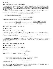
Figure 4<br />
Tun<strong>in</strong>g ∆ SO <strong>in</strong> accordance with the curvature-<strong>in</strong>duced <strong>sp<strong>in</strong></strong>-<strong>orbit</strong> splitt<strong>in</strong>g of the<br />
nanotube Dirac-spectrum. a, Measured effective <strong>sp<strong>in</strong></strong>-<strong>orbit</strong> <strong>coupl<strong>in</strong>g</strong> strength as a function<br />
of V g extracted from spectroscopy measurements like <strong>in</strong> Fig. 3, repeated for <strong>multi</strong>ple<br />
shells. The dashed l<strong>in</strong>e is a fit to the theory. Lower <strong>in</strong>set: Expected dependence of ∆ SO<br />
on ɛ N highlight<strong>in</strong>g the two SOI-contributions ∆ 0 SO and ∆ 1 SO. b, Graphene dispersion-cones<br />
around one K-po<strong>in</strong>t of the graphene Brillou<strong>in</strong> zone. Due to SOI the <strong>sp<strong>in</strong></strong>-up (blue) and<br />
<strong>sp<strong>in</strong></strong>-down (red) Dirac cones are split <strong>in</strong> both the vertical (E) and k ⊥ -direction. The cut<br />
shows the result<strong>in</strong>g CNT band structure also shown <strong>in</strong> the upper <strong>in</strong>set <strong>in</strong> a.<br />
17
Figure 1<br />
a<br />
b<br />
c<br />
V sd (mV)<br />
E add (meV)<br />
2<br />
0<br />
-2<br />
8<br />
3<br />
Fig. 3<br />
-8<br />
4N0~180<br />
+24<br />
-4<br />
+4 +12 +16 +20<br />
+8<br />
+28<br />
5.5 V g (V)<br />
6.5<br />
+32<br />
1<br />
0<br />
dI/dV sd (e 2 /h)
Figure 2<br />
a<br />
∆ KK' = 0<br />
∆ SO = 0<br />
E K' b ∆ KK' > 0<br />
∆ SO = 0<br />
K'<br />
E<br />
A<br />
A<br />
∆ KK'<br />
K'<br />
K<br />
K<br />
K<br />
B<br />
B<br />
B<br />
B ||<br />
B<br />
B ||<br />
c<br />
∆ KK' = 0<br />
∆ SO > 0<br />
E<br />
∆ SO<br />
K'<br />
K'<br />
K<br />
d<br />
∆ KK' > ∆ SO<br />
∆ SO > 0<br />
E<br />
2 2<br />
∆ KK' + ∆ SO<br />
∆ β<br />
SO<br />
δ<br />
γ<br />
K<br />
α<br />
B<br />
B ||<br />
B<br />
B ||
Figure 3<br />
a<br />
V sd (mV)<br />
2<br />
0<br />
-2<br />
3<br />
dI/dV sd (e 2 /h)<br />
0 0.75<br />
4N 0<br />
+1 +2 +3<br />
5.6 V g (V) 5.7<br />
b<br />
B<br />
∆ SO<br />
α<br />
B || = -3T<br />
B ||<br />
-3 3<br />
2∆ SO<br />
d 4N 0 + 1 e 4N 0 +2 f<br />
4N 0 +3<br />
E<br />
δ<br />
β γ<br />
c<br />
V sd (mV)<br />
B || = 3T<br />
1<br />
V sd (mV)<br />
0<br />
0<br />
V sd (mV)<br />
-3<br />
-3 B || (T)<br />
3 -3 B || (T) 3<br />
1.5<br />
g<br />
h<br />
~<br />
S 2<br />
V sd (mV)<br />
∆<br />
0<br />
SO<br />
~<br />
T +<br />
~<br />
T 0<br />
~<br />
T -<br />
~<br />
S 1<br />
-3 B || (T)<br />
3<br />
i<br />
∆ SO<br />
-1<br />
35<br />
-27<br />
d 2 2<br />
I/dV sd (mS/V)<br />
-1.5<br />
-7 B (T)<br />
7 -7 B (T)<br />
7 -7 B (T)<br />
7
Figure 4<br />
a<br />
0.3<br />
E<br />
Fig 3<br />
b<br />
E<br />
∆ SO<br />
∆ SO (meV)<br />
0.0<br />
k ||<br />
∆ SO<br />
k<br />
k ||<br />
Band gap<br />
2∆ 0<br />
2∆ 1<br />
-0.3<br />
-4 0 4 8<br />
V g (V)<br />
ε n
Supplementary Information<br />
<strong>Gate</strong>-<strong>dependent</strong> <strong>sp<strong>in</strong></strong>-<strong>orbit</strong> <strong>coupl<strong>in</strong>g</strong> <strong>in</strong><br />
<strong>multi</strong>-<strong>electron</strong> <strong>car</strong>bon nanotubes<br />
T. S. Jespersen, K. Grove-Rasmussen, J. Paaske,<br />
K. Muraki, T. Fujisawa, J. Nygård, and K. Flensberg<br />
Abstract<br />
We here present the theory and additional experimental data support<strong>in</strong>g<br />
the conclusions <strong>in</strong> the article. First, the <strong>car</strong>bon nanotube dispersion<br />
relation <strong>in</strong>clud<strong>in</strong>g <strong>sp<strong>in</strong></strong>-<strong>orbit</strong> <strong>in</strong>teraction is reviewed start<strong>in</strong>g from a modified<br />
Dirac Hamiltonian, and the s<strong>in</strong>gle-particle model used <strong>in</strong> the fitt<strong>in</strong>g<br />
procedure is expla<strong>in</strong>ed. Second, tunnel<strong>in</strong>g spectroscopy data and the correspond<strong>in</strong>g<br />
analysis used to extract the gate-<strong>dependent</strong> <strong>sp<strong>in</strong></strong>-<strong>orbit</strong> <strong>coupl<strong>in</strong>g</strong><br />
strength are presented.<br />
Contents<br />
1 Carbon nanotube quantum dot with <strong>sp<strong>in</strong></strong>-<strong>orbit</strong> <strong>in</strong>teraction and<br />
iso-<strong>sp<strong>in</strong></strong> mix<strong>in</strong>g 2<br />
1.1 The spectrum for parallel magnetic field . . . . . . . . . . . . . . 3<br />
1.2 Includ<strong>in</strong>g disorder . . . . . . . . . . . . . . . . . . . . . . . . . . 4<br />
1.3 Two-<strong>electron</strong> spectrum . . . . . . . . . . . . . . . . . . . . . . . . 4<br />
2 Supplementary data 4<br />
2.1 Conduction band . . . . . . . . . . . . . . . . . . . . . . . . . . . 5<br />
2.1.1 Sequential tunnel<strong>in</strong>g spectroscopy . . . . . . . . . . . . . 5<br />
2.1.2 Cotunnel<strong>in</strong>g spectroscopy . . . . . . . . . . . . . . . . . . 7<br />
2.2 Valence band . . . . . . . . . . . . . . . . . . . . . . . . . . . . . 13<br />
i
1 Carbon nanotube quantum dot with <strong>sp<strong>in</strong></strong>-<strong>orbit</strong><br />
<strong>in</strong>teraction and iso-<strong>sp<strong>in</strong></strong> mix<strong>in</strong>g<br />
In this section, we discuss the theory for the spectrum of a <strong>car</strong>bon nanotube<br />
quantum dot and how it is modified by <strong>sp<strong>in</strong></strong>-<strong>orbit</strong> <strong>coupl<strong>in</strong>g</strong> and iso-<strong>sp<strong>in</strong></strong> (valley)<br />
mix<strong>in</strong>g. The theory is used to fit the spectroscopic data and to extract the<br />
values of the <strong>sp<strong>in</strong></strong>-<strong>orbit</strong> <strong>coupl<strong>in</strong>g</strong> and KK ′ iso-<strong>sp<strong>in</strong></strong> mix<strong>in</strong>g terms. Start<strong>in</strong>g from<br />
a clean, disorder-free nanotube (i.e. no valley mix<strong>in</strong>g), the Hamiltonian near<br />
the K and K ′ po<strong>in</strong>ts is [1, 2]<br />
H 0 = v ( τp x σ 1 + p y σ 2<br />
)<br />
+ ∆g σ 1 + τs y σ 1 ∆ 1 SO + τs y ∆ 0 SO + V (y), (1)<br />
where σ i , i = 1, 2, 3 are the Pauli matrices <strong>in</strong> the A-B graphene sub-lattice<br />
space, v is the Fermi velocity, and τ = ±1 the iso-<strong>sp<strong>in</strong></strong> <strong>in</strong>dex. Here p y is the<br />
momentum along the tube (coord<strong>in</strong>ate y), while p x is <strong>in</strong> the circumferential<br />
direction (coord<strong>in</strong>ate x). The <strong>sp<strong>in</strong></strong> is described by the Pauli matrix s y with<br />
eigenvalues s = ±1 for eigenstates with <strong>sp<strong>in</strong></strong>s aligned along the nanotube axis,<br />
and V (y) is the conf<strong>in</strong><strong>in</strong>g potential along the tube. The curvature <strong>in</strong>duced mass<br />
term ∆ g depends on the diameter D and the chiral angle η (def<strong>in</strong>ed to be 0<br />
for zigzag tube), see below. The <strong>sp<strong>in</strong></strong>-<strong>orbit</strong> <strong>in</strong>teraction part of the Hamiltonian<br />
has two types of curvature <strong>sp<strong>in</strong></strong>-<strong>orbit</strong> terms: one diagonal and one non-diagonal<br />
<strong>in</strong> A-B space. The strength of these are ∆ 0 SO and ∆1 SO , respectively. The<br />
curvature <strong>in</strong>duced <strong>sp<strong>in</strong></strong>-<strong>orbit</strong> <strong>in</strong>teraction is proportional to 1/D and the <strong>in</strong>traatomic<br />
<strong>sp<strong>in</strong></strong>-<strong>orbit</strong> <strong>in</strong>teraction V so ≃ 6-8 meV [2, 3], while the diagonal part also<br />
depends on the chirality of the tube. Bandstructure calculations [2] give that<br />
∆ 1 SO = α 1<br />
V so<br />
D , α 1 ≈ 0.095 nm (2)<br />
∆ 0 SO = α 2<br />
V so<br />
D cos (3η) , α 2 ≈ −0.090 nm (3)<br />
∆ g = β D 2 cos (3η) , β ≈ 24 meV· nm2 (4)<br />
These values are results of a tight-b<strong>in</strong>d<strong>in</strong>g calculation, with <strong>in</strong>tra atomic <strong>sp<strong>in</strong></strong><strong>orbit</strong><br />
<strong>in</strong>teractions only, and should therefore be taken with some caution. In<br />
our experiment, we cannot determ<strong>in</strong>e D and η <strong>in</strong><strong>dependent</strong>ly, however, us<strong>in</strong>g<br />
an estimate for the diameter, one can compare with the measured value of ∆ 1 SO<br />
and the ratio ∆ 0 SO /∆ g as is done <strong>in</strong> the article.<br />
The eigenstates of H 0 are of the form<br />
ψ τ = e iKτ ·r e ik xx ϕ τs (y). (5)<br />
An external magnetic field B caus<strong>in</strong>g an Aharonov-Bohm flux Φ through a<br />
cross-section of the nanotube shifts the wave number by k Φ = 2Φ/DΦ 0 =<br />
eBD/4, with Φ 0 = h/e. By impos<strong>in</strong>g periodic boundary conditions along<br />
the circumferential direction the wave vector <strong>in</strong> the x-direction becomes k x =<br />
k Φ + 2ν/3D, where ν is 0 or ±1 depend<strong>in</strong>g on the type of tube. For small<br />
bandgap tubes, likely to be the situation <strong>in</strong> the experiment, one has ν = 0.<br />
ii
The longitud<strong>in</strong>al part of the envelope wave function ϕ τs (y) depends on the<br />
conf<strong>in</strong><strong>in</strong>g potential. Let us assume that there is a large region <strong>in</strong> the middle of<br />
the dot with a constant potential. In this region the wavefunction is a superposition<br />
of the two states ϕ τs<br />
± = A ± exp(±iky τs y), ky<br />
τs > 0 [4]. The constants<br />
A ± are determ<strong>in</strong>ed by the boundary conditions at the ends of dot y = 0 and<br />
L. For a sharp term<strong>in</strong>ation of the potential, we have A + ≈ −A − and hence<br />
ky τs ≈ Nπ/L, N = 1, 2, 3, ...<br />
Choos<strong>in</strong>g the <strong>sp<strong>in</strong></strong> quantization axis to be along the tube axis the Hamiltonian<br />
H 0 is then written as<br />
(<br />
0 v(τk<br />
H 0 =<br />
x − ik τs<br />
v(τk x + iky τs ) 0<br />
and the eigenenergies are<br />
E τs = sτ∆ 0 SO ±<br />
y )<br />
) (<br />
+<br />
sτ∆ 0 SO<br />
sτ∆ 1 SO + ∆ g<br />
sτ∆ 1 SO + ∆ g<br />
sτ∆ 0 SO<br />
)<br />
,<br />
(6)<br />
√<br />
(∆ g + τ∆ Φ + τs∆ 1 SO )2 + ϵ N 2<br />
, (7)<br />
with ϵ N = vNπ/L and the Aharonov-Bohm energy given as<br />
∆ Φ = vk Φ = evDB<br />
4<br />
= mω cvD<br />
. (8)<br />
4<br />
F<strong>in</strong>ally, <strong>in</strong> addition to the <strong>orbit</strong>al <strong>coupl<strong>in</strong>g</strong>, the magnetic field also couples to<br />
the <strong>sp<strong>in</strong></strong> degree of freedom by the Zeeman term<br />
H Z = − 1 2 µ sB · s, (9)<br />
where µ s = −gµ B and s i are the Pauli matrices <strong>in</strong> <strong>sp<strong>in</strong></strong> space. Us<strong>in</strong>g the above<br />
solutions <strong>in</strong> absence of H Z as basis states, the Hamiltonian (for each iso<strong>sp<strong>in</strong></strong>) is<br />
(<br />
E1,τ − 1<br />
H 0 + H Z =<br />
2 µ 1<br />
sB ∥ 2 µ )<br />
sB ⊥<br />
1<br />
2 µ sB ⊥ E −1,τ + 1 2 µ , (10)<br />
sB ∥<br />
which is readily diagonalized.<br />
1.1 The spectrum for parallel magnetic field<br />
For the magnetic field parallel to the tube axis the energy of the four states<br />
<strong>in</strong> the quantum dot is to l<strong>in</strong>ear order <strong>in</strong> B given by<br />
where<br />
and<br />
∆ SO = 2∆ 0 SO ±<br />
E τs = E 0 + τs ∆ SO<br />
2<br />
+ (τg orb,τs + 1 2 gs)µ BB ∥ , (11)<br />
√<br />
√<br />
(∆ g + ∆ 1 SO )2 + ϵ 2 N ∓ (∆ g − ∆ 1 SO )2 + ϵ 2 N , (12)<br />
g orb,sτ = evD<br />
( )<br />
∆g + τs∆ 1 SO<br />
√<br />
≈ evD ∆<br />
√ g<br />
. (13)<br />
2µ B<br />
(∆ g + τs∆ 1 SO )2 + ϵ<br />
2 2µ B N<br />
∆ 2 g + ϵ<br />
2 N<br />
Here the upper(lower) sign corresponds to the conduction (valence) band.<br />
iii
1.2 Includ<strong>in</strong>g disorder<br />
S<strong>in</strong>ce iso<strong>sp<strong>in</strong></strong> mix<strong>in</strong>g is an experimentally very important effect, this must<br />
be <strong>in</strong>cluded <strong>in</strong> the modell<strong>in</strong>g of the quantum dot spectrum to correctly describe<br />
the data. The microscopic nature of the sources to KK ′ mix<strong>in</strong>g is <strong>in</strong> general<br />
unknown, but several factors can contribute to the mix<strong>in</strong>g, e.g., <strong>coupl<strong>in</strong>g</strong>s to the<br />
substrate which breaks rotational <strong>in</strong>variance, a random distribution of defects<br />
<strong>in</strong> the tube, or end effects for non-adiabatic conf<strong>in</strong><strong>in</strong>g potentials. In our basis<br />
for the clean wire, these effects result <strong>in</strong> matrix elements ∆ KK ′ = ⟨sτ|H KK ′|s¯τ⟩<br />
(notice that <strong>sp<strong>in</strong></strong> is conserved, assum<strong>in</strong>g non-magnetic symmetry break<strong>in</strong>g only).<br />
Therefore, with KK ′ mix<strong>in</strong>g <strong>in</strong>cluded, the Hamiltonian with<strong>in</strong> a s<strong>in</strong>gle nanotube<br />
shell <strong>in</strong> a magnetic field hav<strong>in</strong>g an angle θ relative to the tube axis is (us<strong>in</strong>g the<br />
basis (K ↑ y , K ′ ↓ y , K ↓ y , K ′ ↑ y ))<br />
⎛<br />
H = E 0 + ⎜<br />
⎝<br />
+ 1 2 gµ BB ⎜<br />
⎝<br />
∆ KK ′ 0 0 E −1,1<br />
⎛<br />
cos θ 0 s<strong>in</strong> θ 0<br />
⎞<br />
⎞<br />
E 1,1 0 0 ∆ KK ′<br />
0 E −1,−1 ∆ KK ′ 0<br />
⎟<br />
0 ∆ KK ′ E 1,−1 0 ⎠<br />
0 − cos θ 0 s<strong>in</strong> θ<br />
s<strong>in</strong> θ − cos θ 0<br />
0 s<strong>in</strong> θ 0 cos θ<br />
⎟<br />
⎠ . (14)<br />
The energies <strong>in</strong> the diagonal E τ,s are taken as the expressions (11) and (13).<br />
After diagonaliz<strong>in</strong>g H we can thus fit the experimentally observed spectrum,<br />
us<strong>in</strong>g ∆ SO , ∆ KK ′ and g orb as fitt<strong>in</strong>g parameters.<br />
1.3 Two-<strong>electron</strong> spectrum<br />
In absence of exchange <strong>coupl<strong>in</strong>g</strong> the two-<strong>electron</strong> spectrum is simply given<br />
by fill<strong>in</strong>g up the one-<strong>electron</strong> states found above. We classify these accord<strong>in</strong>g<br />
to their spectroscopic nature, i.e., how they split <strong>in</strong> a magnetic field and denote<br />
them therefore as s<strong>in</strong>glet- and triplet-like states. They are not s<strong>in</strong>glets and<br />
triplets <strong>in</strong> the usual sense of <strong>sp<strong>in</strong></strong> s<strong>in</strong>glets and triplets.<br />
2 Supplementary data<br />
A central po<strong>in</strong>t of our work is that of Fig. 4a <strong>in</strong> the article, which shows the<br />
gate voltage-dependence of the effective <strong>sp<strong>in</strong></strong>-<strong>orbit</strong> <strong>coupl<strong>in</strong>g</strong> strength ∆ SO . Each<br />
data po<strong>in</strong>t <strong>in</strong> the figure is obta<strong>in</strong>ed by fitt<strong>in</strong>g the s<strong>in</strong>gle-particle energy spectrum<br />
to magnetic field <strong>dependent</strong> tunnel<strong>in</strong>g spectroscopy measurements. This section<br />
presents the analysis of the underly<strong>in</strong>g data. We start by discuss<strong>in</strong>g results from<br />
the conduction band where both sequential- and cotunnel<strong>in</strong>g spectroscopy have<br />
been performed (Sec. 2.1). Subsequently, we present data from the valence band<br />
where a negative value of ∆ SO is found by cotunnel<strong>in</strong>g spectroscopy (Sec. 2.2).<br />
iv
2.1 Conduction band<br />
The <strong>sp<strong>in</strong></strong>-<strong>orbit</strong> parameter ∆ SO has been extracted from 14 shells <strong>in</strong> the conduction<br />
band labeled A-N with shell A(N) correspond<strong>in</strong>g to the lowest(highest)<br />
positive gate voltage. Shell E at V g ≈ 5.6 − 5.7 V corresponds to the quartet for<br />
which the cotunnel<strong>in</strong>g spectroscopy was analyzed <strong>in</strong> Fig. 3 of the article. For<br />
lower gate voltages, the lead-nanotube Schottky barrier is larger, significantly<br />
decreas<strong>in</strong>g the cotunnel<strong>in</strong>g current and for shells A and B cotunnel<strong>in</strong>g spectroscopy<br />
is no-longer feasible. Instead we show <strong>in</strong> section 2.1.1 how sequential<br />
tunnel<strong>in</strong>g spectroscopy also yield the effective <strong>sp<strong>in</strong></strong>-<strong>orbit</strong> <strong>coupl<strong>in</strong>g</strong> strength <strong>in</strong><br />
complete accordance with the s<strong>in</strong>gle-particle model. The additional 12 shells<br />
(C-N) <strong>in</strong> the conduction band allow cotunnell<strong>in</strong>g spectroscopy as presented <strong>in</strong><br />
section 2.1.2.<br />
2.1.1 Sequential tunnel<strong>in</strong>g spectroscopy<br />
The <strong>electron</strong> fill<strong>in</strong>g of quantum states for smaller gate voltages than shown<br />
<strong>in</strong> Fig. 1b <strong>in</strong> the article is analyzed <strong>in</strong> Fig. S1a-b. They show the stability diagram<br />
(S1b) with relatively weak lead-dot tunnel-<strong>coupl<strong>in</strong>g</strong> and the correspond<strong>in</strong>g<br />
addition energies (S1a) extracted from the widths of the diamonds (and scaled<br />
by the gate <strong>coupl<strong>in</strong>g</strong> factor). The large addition energy for every fourth <strong>electron</strong><br />
(red data po<strong>in</strong>ts <strong>in</strong> Fig. S1a) clearly shows the regular four-<strong>electron</strong> shell fill<strong>in</strong>g,<br />
which persists over many <strong>electron</strong>ic shells. A zoom of the two shells labeled<br />
A and B is shown <strong>in</strong> Fig. S1c. Due to the weak <strong>coupl<strong>in</strong>g</strong>, gate-<strong>in</strong><strong>dependent</strong><br />
cotunnel<strong>in</strong>g steps are not observed. Instead, l<strong>in</strong>es parallel to the diamond edges<br />
represent<strong>in</strong>g sequential transport through excited states of the charge-state at<br />
which they term<strong>in</strong>ate are well resolved and can thus be used for spectroscopy.<br />
The l<strong>in</strong>ewidth ≈ 200-300 µeV is determ<strong>in</strong>ed by the tunnel <strong>coupl<strong>in</strong>g</strong> of the quantum<br />
dot to the leads and sets the energy resolution of the measurement. Figure<br />
S1d shows the transconductance dI/dV g vs. V sd and energy (V g ) around the<br />
4N 1 ∼ 120 <strong>electron</strong> charge state with N 1 completely filled four-<strong>electron</strong> shells<br />
as marked <strong>in</strong> Fig. S1c. The Coulomb diamonds are clearly observed and at the<br />
upper (lower) cross<strong>in</strong>g po<strong>in</strong>t one <strong>electron</strong> is added (removed) to the next empty<br />
(last filled) quartet. Note, that by measur<strong>in</strong>g transconductance (rather than<br />
dI/dV sd ), the l<strong>in</strong>es acquire an additional sign reflect<strong>in</strong>g levels enter<strong>in</strong>g(positive<br />
dI/dV g ) or leav<strong>in</strong>g(negative) the available bias w<strong>in</strong>dow [5]. This feature eases<br />
the identification of the relevant levels <strong>in</strong> Fig. S1e, where traces along the black<br />
l<strong>in</strong>e at fixed bias V sd = 4 mV are measured while vary<strong>in</strong>g B ∥ . Consider first<br />
the spectrum of the 4N 1 + 1 charge state (shell B). Increas<strong>in</strong>g B ∥ the doubly<br />
degenerate ground-state splits <strong>in</strong>to two states (α,β) while the excited states<br />
(γ, δ) steeply separates from the ground-state but are only discernably split at<br />
B ∥ ≈ 3 T as emphasized <strong>in</strong> the <strong>in</strong>set. As discussed <strong>in</strong> the article, this asymmetry<br />
is a direct consequence of SOI (see Fig. 2d <strong>in</strong> the article) and the measurements<br />
are accurately reproduced by the calculation overlaid on the B ∥ > 0 part of Fig.<br />
S1e with ∆ SO = 0.2 meV, ∆ KK ′ = 0.58 meV, and g orb = 7.8. Importantly, even<br />
though the SOI is masked <strong>in</strong> the low field regime by the dom<strong>in</strong>at<strong>in</strong>g disorder<br />
v
E add<br />
(meV)<br />
V sd (mV) V sd (mV)<br />
Energy (meV)<br />
15<br />
10<br />
6<br />
0<br />
-6<br />
10<br />
5<br />
0<br />
-5<br />
-10<br />
10<br />
0<br />
a<br />
-12<br />
b<br />
c<br />
-8<br />
4.0 4.1 V gate (V) 4.2 4.3<br />
4N 1 + 1<br />
(α,β)<br />
(γ,δ)<br />
4N 1<br />
4.0<br />
-4<br />
d<br />
4N 1 ~120<br />
+4<br />
+8<br />
+12<br />
+16<br />
A<br />
α<br />
w<br />
δ<br />
α β γ δ<br />
w<br />
γ<br />
β<br />
e<br />
4N 1<br />
+20<br />
+24<br />
4.5 B 5.0<br />
f<br />
+28<br />
g<br />
0.1<br />
0<br />
0.05<br />
0<br />
dI/dV sd (e 2 /h)<br />
dI/dV sd (e 2 /h)<br />
(α,β)<br />
(γ,δ)<br />
4N-1e<br />
-10 1 - 1 θ = 0 θ= π/2<br />
-5 0 5 -5 0 5 -6 0 6<br />
V sd (mV)<br />
B || (T)<br />
B (T)<br />
B = 3.25 T<br />
0 -π/2 π/2<br />
θ (rad.)<br />
3<br />
-3<br />
dI/dV gate (mS)<br />
Figure S1: a, Addition energy as a function of V gate extracted from the stability diagram<br />
<strong>in</strong> b reveal<strong>in</strong>g consecutive four-<strong>electron</strong> shell fill<strong>in</strong>g for a large number of shells. c, Charge<br />
stability diagram of the two shells (A & B) <strong>in</strong> which the sequential tunnel<strong>in</strong>g analysis is made<br />
for 3 and 1 <strong>electron</strong>s <strong>in</strong> the two shells, respectively. d, Transconductance dI/dV g vs. V g and<br />
V sd around a full <strong>electron</strong> shell 4N 1 ≈ 120. Upper(lower) arrow <strong>in</strong>dicates the first excited<br />
state of the first(last) <strong>electron</strong> <strong>in</strong> an otherwise empty(filled) shell. e, Transconductance along<br />
the dashed l<strong>in</strong>e <strong>in</strong> d at V sd = 4 mV measured as a function of parallel magnetic field. Inset<br />
shows a cut along the vertical l<strong>in</strong>e emphasiz<strong>in</strong>g the asymmetric splitt<strong>in</strong>g of the two doublets;<br />
(α, β) vs. (γ, δ) which is the consequence of SOI. Labels α, β, γ, δ refer to Fig. 2d <strong>in</strong> the<br />
article. f, As d but apply<strong>in</strong>g the magnetic field perpendicular to the axis; the doublets split<br />
equally. g, Measurements <strong>in</strong> a constant magnetic field B = 3.25 T while vary<strong>in</strong>g the angle<br />
θ between B and the CNT axis. In e-g the solid l<strong>in</strong>es are a s<strong>in</strong>gle fit to the theory with a<br />
total of only four parameters ∆ SO = 0.2 meV, g orb = 7.8 and ∆ KK ′ = 0.58(0.75) meV for<br />
the 4N 1 + 1(4N 1 − 1) charge state. The theory has been overlaid only for B > 0 not to mask<br />
the data. Dashed l<strong>in</strong>es <strong>in</strong> e and g are excitations belong<strong>in</strong>g to the 4N 1 + 1 charge state also<br />
anticipated by the model with a level-spac<strong>in</strong>g of 6 meV.<br />
vi
V sd (mV)<br />
V sd (mV)<br />
V sd (mV)<br />
4<br />
2<br />
0<br />
-2<br />
-4<br />
5.25<br />
6<br />
b<br />
3<br />
0<br />
-3<br />
-6 0<br />
5.8 6.0 6.2 6.4 6.6 6.8 7.0 7.2 7.4 7.5<br />
6<br />
3<br />
0<br />
-3<br />
a<br />
c<br />
-6<br />
0<br />
7.4 7.6 7.8 8.0 8.2 8.4<br />
Fig. 2, Shell E<br />
0<br />
5.3 5.4 5.5 5.6<br />
5.7<br />
5.8 5.9<br />
L2<br />
G2<br />
M2<br />
C1 D1 D2 E1 E2 E3 F1 F2 F3<br />
H2<br />
I2<br />
V gate (V)<br />
dI/dV sd<br />
(e 2 /h)<br />
2<br />
4<br />
2<br />
0<br />
-2<br />
J2<br />
d<br />
K2<br />
N2<br />
dI/dV sd<br />
(e 2 /h)<br />
1<br />
dI/dV sd<br />
(e 2 /h)<br />
2<br />
dI/dV sd<br />
(e 2 /h)<br />
1<br />
-4 0<br />
9.2 9.3 9.4<br />
Figure S2: a-d, Charge stability diagrams at higher gate voltages with the CNT quantum<br />
dot be<strong>in</strong>g <strong>in</strong> the cotunnel<strong>in</strong>g regime. Arrows po<strong>in</strong>t to charge states where cotunnel<strong>in</strong>g spectroscopy<br />
have been measured (see Figs. S3 and S4). The shell labeled E is analyzed <strong>in</strong> details<br />
<strong>in</strong> Fig. 3 of the article.<br />
and the limited spectroscopic resolution, it clearly stands out <strong>in</strong> the high field<br />
regime as the asymmetry of the splitt<strong>in</strong>g of the two doublets (α, β) vs. (γ, δ).<br />
The correspond<strong>in</strong>g evolution for the 4N 1 −1 charge state is similar (shell A), and<br />
is fitted with the same values for ∆ SO and g orb and tak<strong>in</strong>g ∆ KK ′ = 0.75 meV.<br />
Figure S1f shows the correspond<strong>in</strong>g measurement <strong>in</strong> a perpendicular field<br />
B ⊥ . The level structure is <strong>in</strong> complete agreement with the model which does<br />
not conta<strong>in</strong> any free parameters. S<strong>in</strong>ce ∆ SO is below the spectroscopic resolution<br />
the avoided cross<strong>in</strong>g cannot be clearly discerned <strong>in</strong> the measurement<br />
(unlike the case for the cotunnel<strong>in</strong>g measurements <strong>in</strong> Fig. 3 <strong>in</strong> the article). For<br />
completeness we show <strong>in</strong> Fig. S1g the spectrum for fixed B = 3.25 T while cont<strong>in</strong>uously<br />
vary<strong>in</strong>g the angle θ between the nanotube and the field. Here the<br />
presence of SOI is responsible for the angle dependence of the <strong>in</strong>ternal doublet<br />
splitt<strong>in</strong>gs (arrows), and aga<strong>in</strong> the model is <strong>in</strong> near-perfect agreement with the<br />
data without any free parameters.<br />
2.1.2 Cotunnel<strong>in</strong>g spectroscopy<br />
For higher gate voltages, as already mentioned, the tunnel <strong>coupl<strong>in</strong>g</strong> to the<br />
electrodes <strong>in</strong>creases, and allows for <strong>in</strong>elastic cotunnel<strong>in</strong>g spectroscopy. As shown<br />
<strong>in</strong> Fig. 3 <strong>in</strong> the article, the <strong>sp<strong>in</strong></strong>-<strong>orbit</strong> <strong>coupl<strong>in</strong>g</strong> can <strong>in</strong> this case be directly readoff<br />
by avoided level cross<strong>in</strong>gs <strong>in</strong> perpendicular magnetic field for 1, 2, and 3<br />
vii
<strong>electron</strong>s. Moreover, the <strong>sp<strong>in</strong></strong>-<strong>orbit</strong> <strong>coupl<strong>in</strong>g</strong> breaks the <strong>in</strong>tra-shell <strong>electron</strong>-hole<br />
symmetry, which can be probed by compar<strong>in</strong>g the 1 and 3 <strong>electron</strong> cases <strong>in</strong><br />
parallel field. Figures S2a-d show charge stability diagrams <strong>in</strong> the cotunnel<strong>in</strong>g<br />
regime, where arrows po<strong>in</strong>t to charge states for which field-<strong>dependent</strong> cotunnel<strong>in</strong>g<br />
spectroscopy has been performed. In Fig. S2b-d, the level broaden<strong>in</strong>g<br />
due to electrode-dot <strong>coupl<strong>in</strong>g</strong> is even stronger and the <strong>sp<strong>in</strong></strong>-<strong>orbit</strong> <strong>coupl<strong>in</strong>g</strong> is<br />
extracted from the avoided cross<strong>in</strong>g (of magnitude 2∆ SO ) between the two<strong>electron</strong><br />
s<strong>in</strong>glet-like ˜S 0 and triplet-like ˜T − states <strong>in</strong> perpendicular field.<br />
Figure S3 shows cotunnel<strong>in</strong>g spectroscopy plots (d 2 I/dVsd 2 versus gate and<br />
magnetic field) of shells C, D and F <strong>in</strong> the cotunnel<strong>in</strong>g regime marked <strong>in</strong> Fig.<br />
S2a. The overall features reproduce Fig. 3 <strong>in</strong> the article and show excellent<br />
agreement with the model (black l<strong>in</strong>es). Parameters used <strong>in</strong> the fits are all<br />
summarized <strong>in</strong> Table S1. We now comment on the details observed <strong>in</strong> each<br />
shell, and on how the <strong>sp<strong>in</strong></strong>-<strong>orbit</strong> strength and other parameters are found.<br />
Shell C is analyzed <strong>in</strong> Figs. S3a-b, which show cotunnel<strong>in</strong>g spectroscopy for 1<br />
<strong>electron</strong> <strong>in</strong> perpendicular and parallel magnetic fields. The <strong>sp<strong>in</strong></strong>-<strong>orbit</strong> <strong>coupl<strong>in</strong>g</strong><br />
is directly estimated <strong>in</strong> Fig. S3a from the avoided cross<strong>in</strong>g at B = ±4.5 T<br />
yield<strong>in</strong>g ∆ SO ≃ 140 µeV. Furthermore, the <strong>orbit</strong>al <strong>coupl<strong>in</strong>g</strong> ∆ KK ′ ≃ 495 µeV<br />
and g orb ≃ 5.7 are chosen to produce the theoretical predicted excitations, which<br />
perfectly match the observed threshold of <strong>in</strong>elastic cotunnel<strong>in</strong>g (peaks and dips).<br />
Measurements of shell D is displayed <strong>in</strong> Figs. S3c-g which show a different<br />
behavior than shell C, because the <strong>orbit</strong>al <strong>coupl<strong>in</strong>g</strong> is smaller than the <strong>sp<strong>in</strong></strong><strong>orbit</strong><br />
<strong>coupl<strong>in</strong>g</strong>. The <strong>sp<strong>in</strong></strong>-<strong>orbit</strong> <strong>coupl<strong>in</strong>g</strong> for this shell is extracted <strong>in</strong> Fig. S3d<br />
from the avoided cross<strong>in</strong>g between ˜S 0 and ˜T − states <strong>in</strong> case of the two-<strong>electron</strong><br />
cotunnel<strong>in</strong>g spectroscopy <strong>in</strong> perpendicular magnetic field. The theory matches<br />
the experimental data except <strong>in</strong> Fig. S3d, where some small deviations are<br />
observed at high fields. All other figures show good agreement between theory<br />
and experiment, most remarkably <strong>in</strong> Fig. S3g, where the sample is rotated to an<br />
angle of 22.5 degrees between the nanotube axis and the magnetic field. Note,<br />
that the theory l<strong>in</strong>es <strong>in</strong> Fig. S3e-g at negative biases are only plotted for low<br />
fields to clearly reveal the underly<strong>in</strong>g data.<br />
Shell F is presented <strong>in</strong> Figs. S3h-m, which show the magnetic field dependence<br />
<strong>in</strong> parallel and perpendicular magnetic fields for fill<strong>in</strong>gs 1-3 (as <strong>in</strong> Fig.<br />
3 <strong>in</strong> the article). The overall conductance <strong>in</strong> this shell is higher than for the<br />
shells analyzed above. Moreover, the zero-field threshold of <strong>in</strong>elastic cotunnel<strong>in</strong>g<br />
is seen to vary with fill<strong>in</strong>g, which is not fully accounted for <strong>in</strong> our model.<br />
The clear avoided cross<strong>in</strong>g for 2 <strong>electron</strong>s <strong>in</strong> perpendicular magnetic field (Fig.<br />
S3i), and the break<strong>in</strong>g of <strong>electron</strong>-hole symmetry <strong>in</strong> parallel magnetic field for<br />
<strong>electron</strong> fill<strong>in</strong>gs 1 and 3 (Figs. S3k,m) unambiguously reveal the <strong>sp<strong>in</strong></strong>-<strong>orbit</strong> <strong>in</strong>teraction.<br />
Interest<strong>in</strong>gly, for 2 <strong>electron</strong>s, four (not three as <strong>in</strong> Fig. 3 <strong>in</strong> the article)<br />
excitation l<strong>in</strong>es are seen to emerge from the zero field peak at V sd = 0.25 meV<br />
<strong>in</strong> Fig. S3i. Such behavior is <strong>in</strong>deed expected <strong>in</strong> the presence of f<strong>in</strong>ite exchange<br />
<strong>in</strong>teraction (J > 0), which splits the ˜S 1 and ˜T states. The deviation between<br />
experiment and theory at large B || <strong>in</strong> Fig. S3l may be attributed to avoided<br />
cross<strong>in</strong>gs with states from the next shell. The fitt<strong>in</strong>g parameters are chosen to<br />
ma<strong>in</strong>ly match the <strong>in</strong>elastic cotunnel<strong>in</strong>g thresholds of Figs. S3h (not S3j) and<br />
viii
V sd (mV)<br />
1.5<br />
1.0<br />
0.5<br />
0.0<br />
-0.5<br />
-1.0<br />
-1.5<br />
a<br />
C1<br />
-6 -4 -2 0 2 4<br />
6<br />
2<br />
b C1 ||<br />
1<br />
0<br />
-1<br />
-2<br />
-3 -2 -1 0 1 2<br />
3<br />
2<br />
-2<br />
dI 2 /dVsd 2 (mS/V)<br />
V sd (mV)<br />
V sd (mV)<br />
V sd (mV)<br />
V sd (mV)<br />
1.5<br />
1.0<br />
0.5<br />
0.0<br />
-0.5<br />
-1.0<br />
-1.5<br />
3<br />
2<br />
1<br />
0<br />
-1<br />
-2<br />
-3<br />
c<br />
D1<br />
0 1 2 3<br />
1.5<br />
1.0<br />
0.5<br />
0.0<br />
-0.5<br />
-1.0<br />
-1.5<br />
0 -1 -2 -3 -4 -5 -6 -7 0 1 2 3 4 5 6 7<br />
3<br />
2<br />
e D1 || f D2 g<br />
2<br />
||<br />
D2 22.5deg<br />
1<br />
1<br />
0<br />
0<br />
-1<br />
-2<br />
-3<br />
d<br />
0 1 2 3<br />
1.5<br />
2<br />
h F1 i F2<br />
1.5 j F3<br />
1.0<br />
1<br />
1.0<br />
0.5<br />
0.5<br />
0.0<br />
0<br />
0.0<br />
-0.5<br />
-0.5<br />
-1<br />
-1.0<br />
-1.0<br />
-1.5<br />
-2<br />
-1.5<br />
0 1 2 3 4 5 6 7 -6 -4 -2 0 2 4 6 0 1 2 3 4 5 6 7<br />
3<br />
3<br />
2<br />
20<br />
2 k F1 ||<br />
2 l F2 || m F3 ||<br />
1<br />
1<br />
1<br />
0<br />
0<br />
0<br />
-1<br />
-1<br />
-1<br />
-2<br />
-2<br />
-3<br />
-3<br />
0 1 2 3 -3 -2 -1 0 1 2 3 0 1 2 3<br />
B (T) B (T) B (T)<br />
D2<br />
-1<br />
-2<br />
-2<br />
0 -1 -2 -3 -4 -5 -6 -7<br />
dI 2 /dVsd 2 (mS/V)<br />
5<br />
-5<br />
dI 2 /dVsd 2 (mS/V)<br />
-20<br />
Figure S3: Cotunnel<strong>in</strong>g spectroscopy d 2 I/dVsd 2 versus bias and magnetic field for shell C<br />
(a,b), D (c-g) and F (h-m). The labels <strong>in</strong>dicate shell and <strong>electron</strong> fill<strong>in</strong>g <strong>in</strong> correspondence<br />
with Fig. S2a as well as orientation of the field relative to the <strong>car</strong>bon nanotube axis. Data are<br />
acquired at gate voltages correspond<strong>in</strong>g to the center of the respective Coulomb diamond. The<br />
l<strong>in</strong>es display the excitation spectrum, (i.e., threshold of <strong>in</strong>elastic cotunnel<strong>in</strong>g) predicted by<br />
the s<strong>in</strong>gle- and two-particle model hav<strong>in</strong>g four <strong>in</strong><strong>dependent</strong> parameters, the <strong>orbit</strong>al <strong>coupl<strong>in</strong>g</strong><br />
(disorder) parameter ∆ KK ′, the <strong>sp<strong>in</strong></strong>-<strong>orbit</strong> <strong>coupl<strong>in</strong>g</strong> ∆ SO , the <strong>orbit</strong>al g-factor g orb and the<br />
exchange <strong>in</strong>teraction J. Parameters are summarized <strong>in</strong> Table S1.<br />
ix
V sd (mV) V sd (mV)<br />
V sd (mV)<br />
1.5<br />
1.0<br />
0.5<br />
0.0<br />
-0.5<br />
-1.0<br />
-1.5<br />
1.5<br />
1.0<br />
0.5<br />
0.0<br />
-0.5<br />
-1.0<br />
-1.5<br />
1.5<br />
g<br />
1.0<br />
0.5<br />
0.0<br />
-0.5<br />
a G2 b H2 c<br />
d J2 e K2 f<br />
M2<br />
-1.0<br />
-1.5<br />
-20 20<br />
-100<br />
0 1 2 3 4 5 6 70 1 2 3 4 5 6 7<br />
B (T) B (T)<br />
Λ<br />
h<br />
N2<br />
2∆ SO<br />
100<br />
dI 2 /dV sd<br />
2 (mS/V)<br />
I2<br />
L2<br />
0 1 2 3 4 5 6 7<br />
B (T)<br />
Figure S4: a-h, Cotunnel<strong>in</strong>g spectroscopy dI 2 /dVsd 2 versus bias and perpendicular magnetic<br />
field at half fill<strong>in</strong>g for shells G-N (see stability diagrams <strong>in</strong> Fig. S2b-d). The <strong>sp<strong>in</strong></strong>-<strong>orbit</strong> <strong>coupl<strong>in</strong>g</strong><br />
∆ SO is estimated from the avoided cross<strong>in</strong>g between the s<strong>in</strong>glet-like ˜S 0 and the triplet-like<br />
˜T − states as shown <strong>in</strong> Panel b. The zero field energy difference Λ between the ground and<br />
excited Kramers doublets allows the calculation of the <strong>orbit</strong>al <strong>coupl<strong>in</strong>g</strong> parameter ∆ KK ′ . The<br />
l<strong>in</strong>es represent the calculated spectrum of the two-particle model us<strong>in</strong>g the two parameters<br />
∆ SO and ∆ KK ′ as well as a f<strong>in</strong>ite exchange J. The deviations from the model is attributed<br />
to g-factor renormalization caused by Kondo correlation which are important <strong>in</strong> the strongly<br />
coupled regime (see text). Note, that the color-scale bar for shell N is different than for shells<br />
G-M.<br />
S3i. A more detailed analysis of CNT two-<strong>electron</strong> physics <strong>in</strong>clud<strong>in</strong>g exchange,<br />
disorder and <strong>sp<strong>in</strong></strong>-<strong>orbit</strong> <strong>in</strong>teraction will be presented elsewhere.<br />
For shells G-N (Fig. S2) the lead-dot <strong>coupl<strong>in</strong>g</strong> is even stronger, lead<strong>in</strong>g to<br />
pronounced Kondo physics for 1 and 3 <strong>electron</strong> fill<strong>in</strong>gs and Kondo enhanced<br />
<strong>in</strong>elastic cotunnel<strong>in</strong>g at half fill<strong>in</strong>g [6]. Figure S4 shows two-<strong>electron</strong> cotunnel<strong>in</strong>g<br />
spectroscopy for perpendicular magnetic field. The <strong>orbit</strong>al <strong>coupl<strong>in</strong>g</strong> ∆ KK ′ is<br />
found from the zero-field splitt<strong>in</strong>g Λ between the two Kramers doublets (green<br />
arrows <strong>in</strong> Panel b), and the <strong>sp<strong>in</strong></strong>-<strong>orbit</strong> <strong>coupl<strong>in</strong>g</strong> appears as the zero bias avoided<br />
cross<strong>in</strong>g between the ˜S and ˜T states (black arrows <strong>in</strong> Panel b). Given these<br />
two parameters for each shell the two-<strong>electron</strong> excitation spectrum is calculated<br />
as shown by the black l<strong>in</strong>es. Interest<strong>in</strong>gly, for shells H-M, the ˜S- ˜T avoided<br />
cross<strong>in</strong>gs occur at somewhat higher magnetic fields than predicted. This is<br />
consistent with correlation <strong>in</strong>duced renormalization (lower<strong>in</strong>g) of the g-factor<br />
[7]. As the <strong>coupl<strong>in</strong>g</strong> is decreased <strong>in</strong> case of shell N, the correspondence between<br />
the model and the experimental threshold of cotunnel<strong>in</strong>g is improved confirm<strong>in</strong>g<br />
x
that the effect is related to the <strong>coupl<strong>in</strong>g</strong> and not the <strong>electron</strong> fill<strong>in</strong>g. The g-<br />
factor renormalization is an <strong>in</strong>terest<strong>in</strong>g topic for detailed study and the good<br />
understand<strong>in</strong>g of the s<strong>in</strong>gle-particle spectrum of s<strong>in</strong>gle wall <strong>car</strong>bon nanotube<br />
<strong>electron</strong>ic shells constitutes an optimal start<strong>in</strong>g po<strong>in</strong>t for further explorations.<br />
xi
V sd (mV)<br />
V sd (mV) V sd (mV)<br />
V sd (mV)<br />
V sd (mV)<br />
4<br />
2<br />
0<br />
-2<br />
-4<br />
1.5<br />
1.0<br />
0.5<br />
0.0<br />
-0.5<br />
-1.0<br />
1<br />
0<br />
-1<br />
-2<br />
-3<br />
-3 -2 -1 0 1 2 3 0 1 2 3 -3 -2 -1 0 1 2<br />
1.5<br />
1.0<br />
h W1 i W2 j W3<br />
0.5<br />
0.0<br />
-0.5<br />
-1.0<br />
-1.5<br />
0 1 2 3 4 5 6 7 0 1 2 3 4 5 6 7 0 1 2 3 4 5 6 7<br />
3<br />
k W1 l m<br />
150<br />
2<br />
|| W2 || W3 ||<br />
1<br />
0<br />
-1<br />
-2<br />
a<br />
-2.8 -2.7<br />
V gate (V)<br />
-2.6 -2.5<br />
-1.5<br />
0 1 2 3 4 5 6 7 0 1 2 3 4 5 6 7 0 1 2 3 4 5 6 7<br />
3<br />
2<br />
e W1 2<br />
|| f W2 || g W3 ||<br />
-3<br />
-3 -2 -1 0 1 2<br />
B (T)<br />
W1<br />
W2<br />
W3<br />
b c d<br />
W1 W2 W3<br />
3 0 1 2<br />
B (T)<br />
3 -3 -2 -1 0 1 2<br />
B (T)<br />
3<br />
3<br />
dI 2 /dV sd<br />
2 (mS/V)<br />
0<br />
dI 2 /dV sd<br />
2 (mS/V)<br />
-150<br />
Figure S5: a, Stability diagram show<strong>in</strong>g four-<strong>electron</strong> shell structure <strong>in</strong> the valence band,<br />
where the arrows <strong>in</strong>dicate <strong>electron</strong> fill<strong>in</strong>g 1-3 <strong>in</strong> shell W. We here consider <strong>electron</strong> fill<strong>in</strong>g <strong>in</strong><br />
the valence band shell <strong>in</strong>stead of hole fill<strong>in</strong>g to make easier comparison to the measurements<br />
analyzed <strong>in</strong> the conduction band. Measured dI/dV sd versus bias and perpendicular/parallel<br />
(b-d)/(e-g) magnetic field for <strong>electron</strong> fill<strong>in</strong>g 1, 2 and 3. Numerically obta<strong>in</strong>ed d 2 I/dVsd<br />
2<br />
versus bias and perpendicular/parallel (h-j)/(k-m) magnetic field. The green arrows <strong>in</strong> e, k,<br />
g, m po<strong>in</strong>t to the threshold of <strong>in</strong>elastic cotunnel<strong>in</strong>g <strong>in</strong>volv<strong>in</strong>g the ground- and first excited<br />
states. The blue arrows <strong>in</strong>dicate the magnetic field for which this threshold is zero. This occurs<br />
for B || ≃ 1 T and B || = 0 T for fill<strong>in</strong>gs 1 and 3, respectively, thereby reveal<strong>in</strong>g a negative <strong>sp<strong>in</strong></strong><strong>orbit</strong><br />
<strong>coupl<strong>in</strong>g</strong>. The parameters used <strong>in</strong> the calculated spectrum (l<strong>in</strong>es <strong>in</strong> (h-m)) are given <strong>in</strong><br />
Table S1.<br />
xii
2.2 Valence band<br />
For negative gate voltages transport is <strong>car</strong>ried by holes <strong>in</strong> the valence band<br />
of the small-band-gap semiconduct<strong>in</strong>g <strong>car</strong>bon nanotube. The <strong>coupl<strong>in</strong>g</strong> to the<br />
electrodes is significantly stronger than for the conduction band and Kondo<br />
physics dom<strong>in</strong>ates as seen <strong>in</strong> Fig. S5a. Cotunnel<strong>in</strong>g spectroscopy <strong>in</strong> perpendicular<br />
and parallel magnetic field is measured for 1, 2 and 3 <strong>electron</strong>s <strong>in</strong> one of<br />
the weakest coupled shell W (see arrows). For completeness, both differential<br />
conductance dI/dV sd (S5b-g) and its derivative d 2 I/dVsd 2 (S5h-m) are shown.<br />
Due to significant level broaden<strong>in</strong>g of the cotunnel<strong>in</strong>g features, the (avoided)<br />
cross<strong>in</strong>g <strong>in</strong> perpendicular magnetic field for two <strong>electron</strong>s results <strong>in</strong> a s<strong>in</strong>glettriplet<br />
Kondo resonance as seen <strong>in</strong> Figs. S5c,i [8], and the <strong>sp<strong>in</strong></strong>-<strong>orbit</strong> <strong>coupl<strong>in</strong>g</strong><br />
cannot be directly extracted as the case for weaker <strong>coupl<strong>in</strong>g</strong> (Fig. S4). Instead,<br />
we focus on the parallel magnetic field dependence for <strong>electron</strong> fill<strong>in</strong>g 1 and 3.<br />
In presence of <strong>orbit</strong>al <strong>coupl<strong>in</strong>g</strong> (∆ KK ′ > 0) and positive <strong>sp<strong>in</strong></strong>-<strong>orbit</strong> <strong>coupl<strong>in</strong>g</strong><br />
(∆ SO > 0) as discussed <strong>in</strong> the article, the l<strong>in</strong>es correspond<strong>in</strong>g to the lowest excitation<br />
cross zero bias only at B = 0 for <strong>electron</strong> fill<strong>in</strong>g 1, while a cross<strong>in</strong>g also<br />
occurs at f<strong>in</strong>ite parallel magnetic fields for fill<strong>in</strong>g 3 (see Fig. 3d,f <strong>in</strong> the article<br />
and Fig. S3k,m). Similar behavior is seen for shell W <strong>in</strong> Fig. S5k, m where the<br />
one and three <strong>electron</strong> behavior now is <strong>in</strong>terchanged: the cotunnel<strong>in</strong>g threshold<br />
correspond<strong>in</strong>g to the lowest excitation (green arrows <strong>in</strong> Fig. S5e, k) cross at<br />
f<strong>in</strong>ite fields for fill<strong>in</strong>g 1 (blue arrow). This shows that the <strong>sp<strong>in</strong></strong>-<strong>orbit</strong> <strong>coupl<strong>in</strong>g</strong><br />
∆ SO is negative thus favor<strong>in</strong>g antiparallel rather than parallel orientation of the<br />
<strong>orbit</strong>al and <strong>sp<strong>in</strong></strong> angular momentum (see Fig. S6 for the effect of negative ∆ SO<br />
on the level structure). The theoretically expected cotunnel<strong>in</strong>g thresholds are<br />
<strong>in</strong>dicated by the black l<strong>in</strong>es <strong>in</strong> Fig. S4 with the values of the <strong>orbit</strong>al <strong>coupl<strong>in</strong>g</strong><br />
and the <strong>sp<strong>in</strong></strong>-<strong>orbit</strong> <strong>coupl<strong>in</strong>g</strong> listed <strong>in</strong> Table S1. As discussed <strong>in</strong> the article, a<br />
negative <strong>sp<strong>in</strong></strong>-<strong>orbit</strong> <strong>coupl<strong>in</strong>g</strong> is <strong>in</strong>deed consistent with the expectation from the<br />
Dirac band structure, and our f<strong>in</strong>d<strong>in</strong>gs illustrate a different regime than previously<br />
reported, which found a positive <strong>sp<strong>in</strong></strong>-<strong>orbit</strong> <strong>coupl<strong>in</strong>g</strong> for the (first) <strong>car</strong>riers<br />
a b<br />
∆ E<br />
SO > 0 ∆ SO < 0<br />
∆ KK' > ∆ SO<br />
∆ KK' > |∆ SO |<br />
B<br />
B ||<br />
B<br />
E<br />
B ||<br />
Figure S6: Energy spectrum of quartet with positive (a) and negative (b) <strong>sp<strong>in</strong></strong>-<strong>orbit</strong> <strong>coupl<strong>in</strong>g</strong><br />
result<strong>in</strong>g <strong>in</strong> an <strong>in</strong>terchange of the two Kramers doublets (red arrows).<br />
xiii
V sd (mV)<br />
0.75<br />
0<br />
-0.75<br />
1.5<br />
a Z1 Z3 Y1 Y3<br />
B ||=0T<br />
-3.30 -3.25 -3.20 -3.15 -3.10 -3.05<br />
V gate (V)<br />
b Y1 || c Y3 ||<br />
dI/dV sd (e 2 /h)<br />
1.1<br />
0<br />
V sd (mV)<br />
0<br />
-1.5<br />
1.5<br />
d Z1 || e Z3 ||<br />
dI 2 /dV sd<br />
2 (mS/V)<br />
50<br />
V sd (mV)<br />
0<br />
-50<br />
V sd (mV)<br />
-1.5<br />
-3 -2 -1 0 1 2 3 -3 -2 -1 0 1 2 3<br />
f B || (T)<br />
B || (T)<br />
1.0<br />
Z1 Z3 Y1 Y3 X1 X3<br />
0.5<br />
0<br />
-0.5<br />
~200µV<br />
~290µV<br />
0.8<br />
B ||=2T<br />
-1.0<br />
-3.30 -3.25 -3.20 -3.15 -3.10 -3.05 -3.00 -2.95 0<br />
V gate (V)<br />
dI/dV sd (e 2 /h)<br />
Figure S7: a, Stability diagram of shells Y and Z <strong>in</strong> the valence band from a different<br />
cooldown of the same sample. b-e, Cotunnel<strong>in</strong>g spectroscopy d 2 I/dVsd 2 versus V sd and parallel<br />
magnetic field of shell Y and Z show<strong>in</strong>g the break<strong>in</strong>g of <strong>electron</strong>-hole symmetry reflect<strong>in</strong>g a<br />
negative <strong>sp<strong>in</strong></strong>-<strong>orbit</strong> <strong>coupl<strong>in</strong>g</strong> strength, i.e., the lowest excitation l<strong>in</strong>es cross at respectively<br />
f<strong>in</strong>ite and zero field for b,d and c,e. The black l<strong>in</strong>es are the expected excitations given the<br />
parameters <strong>in</strong> Table S1. (f) Stability diagram at B || = 2 T show<strong>in</strong>g shells X, Y, and Z. The<br />
<strong>sp<strong>in</strong></strong>-<strong>orbit</strong> <strong>in</strong>teraction is revealed by a difference <strong>in</strong> splitt<strong>in</strong>g of the Kondo resonance for 1 and<br />
3 <strong>electron</strong>s <strong>in</strong> a shell (yellow and blue arrows). A negative <strong>sp<strong>in</strong></strong>-<strong>orbit</strong> <strong>in</strong>teraction of similar<br />
strength is therefore <strong>in</strong>ferred also for shell X.<br />
<strong>in</strong> both the conduction and valence band [3].<br />
The analysis is repeated for shells Y and Z at larger negative gate voltages<br />
xiv
presented <strong>in</strong> Fig. S7a, where the asymmetry between the 1 and 3 <strong>electron</strong> behavior<br />
is observed <strong>in</strong> Figs. S7b-e. By compar<strong>in</strong>g to theory (black l<strong>in</strong>es) we f<strong>in</strong>d<br />
a <strong>sp<strong>in</strong></strong>-<strong>orbit</strong> <strong>coupl<strong>in</strong>g</strong> strength ∼ −75 µV for both shells. F<strong>in</strong>ally, we show that<br />
the <strong>sp<strong>in</strong></strong>-obit <strong>coupl<strong>in</strong>g</strong> also is observed <strong>in</strong> stability diagrams as an asymmetric<br />
splitt<strong>in</strong>g of the 1 and 3 <strong>electron</strong> Kondo resonances <strong>in</strong> parallel magnetic fields.<br />
This is illustrated <strong>in</strong> Fig. S7f show<strong>in</strong>g a stability diagram of the three shells X,<br />
Y and Z at B || = 2 T, where an asymmetric splitt<strong>in</strong>g of the Kramers doublets<br />
for fill<strong>in</strong>g 1 and 3 is clearly revealed. The alternat<strong>in</strong>g behavior of small and large<br />
splitt<strong>in</strong>g is highlighted by pairs of yellow and blue arrows. In the case of shell<br />
Y the difference <strong>in</strong> splitt<strong>in</strong>gs is ∼ 90 µV, consistent with the <strong>sp<strong>in</strong></strong>-<strong>orbit</strong> <strong>coupl<strong>in</strong>g</strong><br />
strength deduced above. We therefore conclude that also shell X has a negative<br />
<strong>sp<strong>in</strong></strong>-<strong>orbit</strong> <strong>coupl<strong>in</strong>g</strong> <strong>in</strong> the same order as shell Y and Z.<br />
References<br />
[1] J. Jeong and H. Lee, Phys. Rev. B 80 (2009).<br />
[2] W. Izumida, K. Sato, and R. Saito, J. Phys. Soc. Jpn. 78, 074707 (2009).<br />
[3] F. Kuemmeth, et al., Nature 452, 448 (2008).<br />
[4] D. V. Bulaev, B. Trauzettel, and D. Loss, Phys. Rev. B 77, 235301 (2008).<br />
[5] L. Kouwenhoven, D. Aust<strong>in</strong>g, and S. Tarucha, Rep. Prog. Phys. 64, 701<br />
(2001).<br />
[6] J. Paaske, et al., Nature Physics 2, 460 (2006).<br />
[7] A. C. Hewson, J. Bauer, and W. Koller, Phys. Rev. B 73, 045117 (2006).<br />
[8] J. Nygård, D. H. Cobden, and P. E. L<strong>in</strong>delof, Nature 408, 342 (2000).<br />
xv
Shell # V gate (V) Λ(µeV) ∆ SO (µeV) ∆ KK ′(µeV) J(µeV) g orb<br />
A 4.12 775 200 750 - 7.8<br />
B 4.25 615 200 580 - 7.8<br />
C 5.40 515 140 495 - 5.7<br />
D 5.55 200 185 75 0 5.5<br />
E (Fig. 3) 5.68 475 150 450 0 5.7<br />
F 5.78 560 100 550 450 5.4<br />
G 6.04 195 115 155 - -<br />
H 6.30 315 65 310 - -<br />
I 6.57 190 95 165 - -<br />
J 7.09 245 125 210 100 -<br />
K 7.36 390 60 385 - -<br />
L 7.56 435 60 430 - -<br />
M 7.69 410 60 405 - -<br />
N 9.34 330 65 325 - -<br />
W -2.67 225 -100 200 0 ≃ 4.4<br />
X -2.98 - ≃ −75 - - -<br />
Y -3.14 ≃ 605 ≃ −75 ≃ 600 - ≃ 5.8<br />
Z -3.25 ≃ 705 ≃ −75 ≃ 700 - ≃ 5.8<br />
Table S1: Parameters extracted for each measured shell <strong>in</strong> the conduction (A-N) and valence<br />
(W-Z) band. Shells A and B are the only shells analyzed <strong>in</strong> the sequential tunnel<strong>in</strong>g regime<br />
(Fig. S1), while C-F are <strong>in</strong> the weak cotunnel<strong>in</strong>g regime (Fig. S3 and Fig. 3). As the levelbroaden<strong>in</strong>g<br />
<strong>in</strong>creases even further (G-N), the <strong>sp<strong>in</strong></strong>-<strong>orbit</strong> <strong>coupl<strong>in</strong>g</strong> ∆ SO and the energy splitt<strong>in</strong>g<br />
between the two Kramers doublets Λ is estimated at half fill<strong>in</strong>g by the zero-bias avoided<br />
cross<strong>in</strong>g at f<strong>in</strong>ite magnetic field and the zero-field <strong>in</strong>elastic cotunnel<strong>in</strong>g<br />
√<br />
threshold, respectively<br />
(see Fig. S4b). The <strong>orbit</strong>al <strong>coupl<strong>in</strong>g</strong> is related as ∆ KK ′ = Λ 2 − ∆ 2 SO , and <strong>in</strong> some cases<br />
a ˜S 0 - ˜T splitt<strong>in</strong>g caused by exchange <strong>in</strong>teraction J can be observed (J = 0 means that the<br />
exchange <strong>in</strong>teraction is smaller than the spectroscopic l<strong>in</strong>e width <strong>in</strong> the shell). In the valence<br />
band, the <strong>sp<strong>in</strong></strong>-<strong>orbit</strong> <strong>coupl<strong>in</strong>g</strong> is observed by the break<strong>in</strong>g of <strong>electron</strong>-hole symmetry for 1 and<br />
3 <strong>electron</strong>s <strong>in</strong> a parallel magnetic field (S5 and S7). The uncerta<strong>in</strong>ty of the <strong>sp<strong>in</strong></strong>-<strong>orbit</strong> <strong>coupl<strong>in</strong>g</strong><br />
strength is shown <strong>in</strong> Fig. 4 <strong>in</strong> the article. The dashes <strong>in</strong>dicate that measurement have not<br />
been made to extract the correspond<strong>in</strong>g parameter. Note, that the decreas<strong>in</strong>g values of g orb<br />
versus gate voltage (fill<strong>in</strong>g) <strong>in</strong> the conduction band is consistent with Eq. (13). As expected<br />
the <strong>orbit</strong>al <strong>coupl<strong>in</strong>g</strong> ∆ KK ′ shows no gate voltage correlation.<br />
xvi