Lenze Asynchronous Synchronous Servo Motors - Lpo-usa.com
Lenze Asynchronous Synchronous Servo Motors - Lpo-usa.com
Lenze Asynchronous Synchronous Servo Motors - Lpo-usa.com

You also want an ePaper? Increase the reach of your titles
YUMPU automatically turns print PDFs into web optimized ePapers that Google loves.
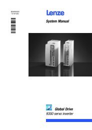
BA 33.0006−EN<br />
.@KL<br />
Ä.@KLä<br />
Operating Instructions<br />
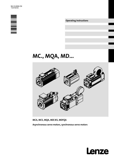
MC., MQA, MD...<br />
MCA, MCS, MQA, MDKS, MDFQA<br />
<strong>Asynchronous</strong> servo motors, synchronous servo motors
Please read these instructions before you start working!<br />
Follow the enclosed safety instructions.<br />
Detailed information is given in the corresponding operating instructions.<br />
0Fig. 0Tab. 0<br />
2 <br />
BA 33.0006−EN 1.0
Contents<br />
i<br />
1 About this documentation . . . . . . . . . . . . . . . . . . . . . . . . . . . . . . . . . . . . . . . . . . . . . . . . . . 5<br />
1.1 Document history . . . . . . . . . . . . . . . . . . . . . . . . . . . . . . . . . . . . . . . . . . . . . . . . . . . . 5<br />
1.2 Conventions used . . . . . . . . . . . . . . . . . . . . . . . . . . . . . . . . . . . . . . . . . . . . . . . . . . . . 6<br />
1.3 Terminology used . . . . . . . . . . . . . . . . . . . . . . . . . . . . . . . . . . . . . . . . . . . . . . . . . . . . 6<br />
1.4 Notes used . . . . . . . . . . . . . . . . . . . . . . . . . . . . . . . . . . . . . . . . . . . . . . . . . . . . . . . . . . 7<br />
2 Safety instructions . . . . . . . . . . . . . . . . . . . . . . . . . . . . . . . . . . . . . . . . . . . . . . . . . . . . . . . . . 8<br />
2.1 General safety instructions for drive <strong>com</strong>ponents . . . . . . . . . . . . . . . . . . . . . . . . . . 8<br />
2.2 Application as directed . . . . . . . . . . . . . . . . . . . . . . . . . . . . . . . . . . . . . . . . . . . . . . . . 11<br />
2.3 Improper use . . . . . . . . . . . . . . . . . . . . . . . . . . . . . . . . . . . . . . . . . . . . . . . . . . . . . . . . 11<br />
2.4 Residual hazards . . . . . . . . . . . . . . . . . . . . . . . . . . . . . . . . . . . . . . . . . . . . . . . . . . . . . 12<br />
3 Product description . . . . . . . . . . . . . . . . . . . . . . . . . . . . . . . . . . . . . . . . . . . . . . . . . . . . . . . . 13<br />
3.1 Identification . . . . . . . . . . . . . . . . . . . . . . . . . . . . . . . . . . . . . . . . . . . . . . . . . . . . . . . . 13<br />
3.1.1 Nameplate . . . . . . . . . . . . . . . . . . . . . . . . . . . . . . . . . . . . . . . . . . . . . . . . . . 14<br />
3.1.2 Product key . . . . . . . . . . . . . . . . . . . . . . . . . . . . . . . . . . . . . . . . . . . . . . . . . . 16<br />
4 Technical data . . . . . . . . . . . . . . . . . . . . . . . . . . . . . . . . . . . . . . . . . . . . . . . . . . . . . . . . . . . . 19<br />
4.1 General data and operating conditions . . . . . . . . . . . . . . . . . . . . . . . . . . . . . . . . . 19<br />
4.2 Holding brake (option) . . . . . . . . . . . . . . . . . . . . . . . . . . . . . . . . . . . . . . . . . . . . . . . . 20<br />
4.2.1 Important notes . . . . . . . . . . . . . . . . . . . . . . . . . . . . . . . . . . . . . . . . . . . . . . 20<br />
4.2.2 Permanent magnet holding brakes . . . . . . . . . . . . . . . . . . . . . . . . . . . . . . 22<br />
4.2.3 Spring−applied holding brakes . . . . . . . . . . . . . . . . . . . . . . . . . . . . . . . . . . 23<br />
5 Mechanical installation . . . . . . . . . . . . . . . . . . . . . . . . . . . . . . . . . . . . . . . . . . . . . . . . . . . . . 25<br />
5.1 Preparation . . . . . . . . . . . . . . . . . . . . . . . . . . . . . . . . . . . . . . . . . . . . . . . . . . . . . . . . . . 25<br />
5.2 Assembly of built−on accessories . . . . . . . . . . . . . . . . . . . . . . . . . . . . . . . . . . . . . . . . 25<br />
5.3 Installation . . . . . . . . . . . . . . . . . . . . . . . . . . . . . . . . . . . . . . . . . . . . . . . . . . . . . . . . . . 26<br />
6 Electrical installation . . . . . . . . . . . . . . . . . . . . . . . . . . . . . . . . . . . . . . . . . . . . . . . . . . . . . . . 27<br />
6.1 Important notes . . . . . . . . . . . . . . . . . . . . . . . . . . . . . . . . . . . . . . . . . . . . . . . . . . . . . . 27<br />
6.2 Wiring according to EMC . . . . . . . . . . . . . . . . . . . . . . . . . . . . . . . . . . . . . . . . . . . . . . 28<br />
6.3 Plug connectors . . . . . . . . . . . . . . . . . . . . . . . . . . . . . . . . . . . . . . . . . . . . . . . . . . . . . . 28<br />
6.3.1 Motor . . . . . . . . . . . . . . . . . . . . . . . . . . . . . . . . . . . . . . . . . . . . . . . . . . . . . . . 28<br />
6.3.2 AC/DC holding brake (optional) . . . . . . . . . . . . . . . . . . . . . . . . . . . . . . . . . 29<br />
6.3.3 Fan . . . . . . . . . . . . . . . . . . . . . . . . . . . . . . . . . . . . . . . . . . . . . . . . . . . . . . . . . 30<br />
6.3.4 Feedback system . . . . . . . . . . . . . . . . . . . . . . . . . . . . . . . . . . . . . . . . . . . . . 31<br />
BA 33.0006−EN 1.0<br />
3
i<br />
Contents<br />
6.4 Terminal box . . . . . . . . . . . . . . . . . . . . . . . . . . . . . . . . . . . . . . . . . . . . . . . . . . . . . . . . 32<br />
6.4.1 Motor . . . . . . . . . . . . . . . . . . . . . . . . . . . . . . . . . . . . . . . . . . . . . . . . . . . . . . . 33<br />
6.4.2 AC holding brake (optional) . . . . . . . . . . . . . . . . . . . . . . . . . . . . . . . . . . . . 34<br />
6.4.3 DC holding brake (optional) . . . . . . . . . . . . . . . . . . . . . . . . . . . . . . . . . . . . 34<br />
6.4.4 Fan . . . . . . . . . . . . . . . . . . . . . . . . . . . . . . . . . . . . . . . . . . . . . . . . . . . . . . . . . 35<br />
6.4.5 Feedback system . . . . . . . . . . . . . . . . . . . . . . . . . . . . . . . . . . . . . . . . . . . . . 36<br />
7 Commissioning and operation . . . . . . . . . . . . . . . . . . . . . . . . . . . . . . . . . . . . . . . . . . . . . . . 38<br />
7.1 Important notes . . . . . . . . . . . . . . . . . . . . . . . . . . . . . . . . . . . . . . . . . . . . . . . . . . . . . . 38<br />
7.2 Before switching on . . . . . . . . . . . . . . . . . . . . . . . . . . . . . . . . . . . . . . . . . . . . . . . . . . 38<br />
7.3 Functional test . . . . . . . . . . . . . . . . . . . . . . . . . . . . . . . . . . . . . . . . . . . . . . . . . . . . . . . 39<br />
7.4 Functional test . . . . . . . . . . . . . . . . . . . . . . . . . . . . . . . . . . . . . . . . . . . . . . . . . . . . . . 39<br />
7.5 During operation . . . . . . . . . . . . . . . . . . . . . . . . . . . . . . . . . . . . . . . . . . . . . . . . . . . . . 39<br />
8 Maintenance/repair . . . . . . . . . . . . . . . . . . . . . . . . . . . . . . . . . . . . . . . . . . . . . . . . . . . . . . . 40<br />
8.1 Important notes . . . . . . . . . . . . . . . . . . . . . . . . . . . . . . . . . . . . . . . . . . . . . . . . . . . . . . 40<br />
8.2 Maintenance intervals . . . . . . . . . . . . . . . . . . . . . . . . . . . . . . . . . . . . . . . . . . . . . . . . 40<br />
8.2.1 Holding brake . . . . . . . . . . . . . . . . . . . . . . . . . . . . . . . . . . . . . . . . . . . . . . . . 41<br />
8.3 Maintenance operations . . . . . . . . . . . . . . . . . . . . . . . . . . . . . . . . . . . . . . . . . . . . . . . 41<br />
8.3.1 Holding brake . . . . . . . . . . . . . . . . . . . . . . . . . . . . . . . . . . . . . . . . . . . . . . . . 41<br />
8.3.2 Blower . . . . . . . . . . . . . . . . . . . . . . . . . . . . . . . . . . . . . . . . . . . . . . . . . . . . . . 42<br />
8.4 Repair . . . . . . . . . . . . . . . . . . . . . . . . . . . . . . . . . . . . . . . . . . . . . . . . . . . . . . . . . . . . . . 42<br />
9 Troubleshooting and fault elimination . . . . . . . . . . . . . . . . . . . . . . . . . . . . . . . . . . . . . . . 43<br />
4 <br />
BA 33.0006−EN 1.0
About this documentation<br />
Document history<br />
1<br />
1 About this documentation<br />
Contents<br />
ƒ<br />
ƒ<br />
The present operating instructions are intended for safe working on and with the<br />
motors. They contain safety instructions that must be observed.<br />
All personnel working on and with the motors must have the operating instructions<br />
available during work and observe the information and notes relevant for them.<br />
ƒ The operating instructions must always be <strong>com</strong>plete and in a perfectly readable<br />
state.<br />
If the information and notes provided in this documentation do not meet your<br />
requirements, please refer to the controller and/or gearbox documentation.<br />
Tip!<br />
Documentation and software updates for further <strong>Lenze</strong> products can be found<br />
on the Internet in the "Services & Downloads" area under<br />
http://www.<strong>Lenze</strong>.<strong>com</strong><br />
Validity<br />
This documentation is valid for servo motors:<br />
Type<br />
MCS<br />
MCA<br />
MQA<br />
MDFQA<br />
MDKS<br />
Designation<br />
<strong>Synchronous</strong> servo motors<br />
<strong>Asynchronous</strong> servo motors<br />
<strong>Synchronous</strong> servo motors<br />
Target group<br />
This documentation is intended for qualified personnel according to IEC 364.<br />
Qualified, skilled personnel are persons who have the qualifications necessary for the work<br />
activities to be undertaken during the assembly, installation, <strong>com</strong>issioning, and operation<br />
of the product.<br />
1.1 Document history<br />
Material number Version Description<br />
.@KL 1.0 07/2009 TD09 First edition<br />
BA 33.0006−EN 1.0<br />
5
1<br />
About this documentation<br />
Conventions used<br />
1.2 Conventions used<br />
This documentation uses the following conventions to distinguish different types of<br />
information:<br />
Type of information Identification Examples/notes<br />
Cross−references Refers to additional information. For example<br />
10 = see page 10<br />
1.3 Terminology used<br />
Term<br />
Motor<br />
Controller<br />
Drive system<br />
In the following text used for<br />
<strong>Servo</strong> motor in the versions according to the product key, see page 16 to<br />
page 18 .<br />
Any servo inverter<br />
Any frequency inverter<br />
Drive systems with servo motors and with other <strong>Lenze</strong> drive <strong>com</strong>ponents<br />
6 <br />
BA 33.0006−EN 1.0
About this documentation<br />
Notes used<br />
1<br />
1.4 Notes used<br />
The following pictographs and signal words are used in this documentation to indicate<br />
dangers and important information:<br />
Safety instructions<br />
Structure of safety instructions:<br />
Danger!<br />
(characterises the type and severity of danger)<br />
Note<br />
(describes the danger and gives information about how to prevent dangerous<br />
situations)<br />
Pictograph and signal word<br />
Danger!<br />
Danger!<br />
Stop!<br />
Meaning<br />
Danger of personal injury through dangerous electrical voltage.<br />
Reference to an imminent danger that may result in death or<br />
serious personal injury if the corresponding measures are not<br />
taken.<br />
Danger of personal injury through a general source of danger.<br />
Reference to an imminent danger that may result in death or<br />
serious personal injury if the corresponding measures are not<br />
taken.<br />
Danger of property damage.<br />
Reference to a possible danger that may result in property<br />
damage if the corresponding measures are not taken.<br />
Application notes<br />
Pictograph and signal word<br />
Note!<br />
Tip!<br />
<br />
Meaning<br />
Important note to ensure troublefree operation<br />
Useful tip for simple handling<br />
Reference to another documentation<br />
Special safety instructions and application notes for UL and UR<br />
Pictograph and signal word<br />
<br />
<br />
Warnings!<br />
Warnings!<br />
Meaning<br />
Safety or application note for the operation of a UL−approved<br />
device in UL−approved systems.<br />
Possibly the drive system is not operated in <strong>com</strong>pliance with UL<br />
if the corresponding measures are not taken.<br />
Safety or application note for the operation of a UR−approved<br />
device in UL−approved systems.<br />
Possibly the drive system is not operated in <strong>com</strong>pliance with UL<br />
if the corresponding measures are not taken.<br />
BA 33.0006−EN 1.0<br />
7
2<br />
Safety instructions<br />
General safety instructions for drive <strong>com</strong>ponents<br />
2 Safety instructions<br />
2.1 General safety instructions for drive <strong>com</strong>ponents<br />
(in accordance with Low−Voltage Directive 2006/95/EC)<br />
At the time of dispatch, the drive <strong>com</strong>ponents are in line with the latest state of the art and<br />
can be regarded as operationally safe.<br />
Scope<br />
The following safety instructions generally apply to <strong>Lenze</strong> drive system <strong>com</strong>ponents.<br />
Be absolutely sure to observe the product−specific safety and application notes given in<br />
this documentation!<br />
8 <br />
BA 33.0006−EN 1.0
Safety instructions<br />
General safety instructions for drive <strong>com</strong>ponents<br />
2<br />
General hazards<br />
Danger!<br />
Disregarding the following basic safety measures may lead to severe personal<br />
injury and damage to material:<br />
ƒ <strong>Lenze</strong> drive <strong>com</strong>ponents ...<br />
– ... must only be used as directed.<br />
– ... must never be <strong>com</strong>missioned in the event of visible damage.<br />
– ... must never be technically modified.<br />
– ... must never be <strong>com</strong>missioned before they have been <strong>com</strong>pletely mounted.<br />
– ... must never be operated without the covers required.<br />
– ... can − depending on the degree of protection − have live, movable or rotating<br />
parts during operation. Surfaces can be hot.<br />
ƒ For <strong>Lenze</strong> drive <strong>com</strong>ponents ...<br />
– ... use only the accessories approved.<br />
– ... use only original spare parts from <strong>Lenze</strong>.<br />
ƒ<br />
ƒ<br />
ƒ<br />
Observe all specifications given in the attached documentation.<br />
– This is the prerequisite for safe and trouble−free operation and achieving the<br />
specified product features.<br />
Only qualified personnel may work with and on <strong>Lenze</strong> drive <strong>com</strong>ponents.<br />
According to IEC 364 and CENELEC HD 384, these are persons ...<br />
– ... who are familiar with the installation, assembly, <strong>com</strong>missioning and operation<br />
of the product.<br />
– ... who have the corresponding qualifications for their work.<br />
– ... who know all regulations for the prevention of accidents, directives and laws<br />
applicable on site and are able to apply them.<br />
During operation, the drive system or <strong>com</strong>ponents thereof can − depending on the<br />
degree of protection − have live parts as well as parts that move or rotate. Surfaces<br />
can be hot.<br />
If the necessary cover is removed or if the product is improperly used, wrongly installed<br />
or incorrectly operated, there is a danger of serious personal injury or damage to<br />
property.<br />
BA 33.0006−EN 1.0<br />
9
2<br />
Safety instructions<br />
General safety instructions for drive <strong>com</strong>ponents<br />
Transport, storage<br />
ƒ<br />
ƒ<br />
Transport and storage in a dry, low−vibration environment without aggressive<br />
atmosphere; preferably in the packaging provided by the manufacturer.<br />
– Protect against dust and shocks.<br />
– Comply with climatic conditions according to the technical data.<br />
Before transport<br />
– Check that all transport locking devices are mounted.<br />
– Tightly fasten all ring bolts.<br />
Note!<br />
Do not apply extra loads to the product as the ring bolts are designed for the<br />
weight of the motor only (refer to the catalogue for the weight).<br />
Mechanical installation<br />
ƒ Install the product according to the regulations of the corresponding<br />
documentation. In particular observe the section "Operating conditions" in the<br />
chapter "Technical data".<br />
ƒ<br />
Provide for a careful handling and avoid mechanical overload. During handling<br />
neither bend <strong>com</strong>ponents, nor change the insulation distances.<br />
Electrical installation<br />
ƒ Carry out the electrical installation according to the relevant regulations (e. g. cable<br />
cross−sections, fusing, connection to the PE conductor). Additional notes are<br />
included in the documentation.<br />
ƒ<br />
ƒ<br />
ƒ<br />
The documentation contains notes for the EMC−<strong>com</strong>pliant installation (shielding,<br />
earthing, arrangement of filters and installation of the cables). The manufacturer of<br />
the system or machine is responsible for the <strong>com</strong>pliance with the limit values<br />
required in connection with EMC legislation.<br />
For <strong>com</strong>pliance with the limit values for radio interference emission at the site of<br />
installation, the <strong>com</strong>ponents − if specified in the technical data − have to be mounted<br />
in housings (e. g. control cabinets). The housings have to enable an EMC−<strong>com</strong>pliant<br />
installation. In particular observe that for example control cabinet doors preferably<br />
have a circumferential metallic connection to the housing. Reduce openings or<br />
cutouts through the housing to a minimum.<br />
Only plug in or remove pluggable terminals in the deenergised state!<br />
Commissioning<br />
ƒ If required, you have to equip the system with additional monitoring and protective<br />
devices in accordance with the respective valid safety regulations (e. g. law on<br />
technical equipment, regulations for the prevention of accidents).<br />
ƒ<br />
Before <strong>com</strong>missioning remove transport locking devices and keep them for later<br />
transports.<br />
10 <br />
BA 33.0006−EN 1.0
Safety instructions<br />
Application as directed<br />
2<br />
Operation<br />
ƒ<br />
Keep all protective covers and doors closed during operation.<br />
2.2 Application as directed<br />
Low−voltage machines are no household appliances, they are designed as <strong>com</strong>ponents for<br />
industrial or professional use in terms of IEC/EN 61000−3−2 only.<br />
They <strong>com</strong>ply with the harmonised standards of the series IEC/EN60034.<br />
Low−voltage machines are <strong>com</strong>ponents for installation into machines as defined in the<br />
Machinery Directive 98/37/EC. Commissioning is prohibited until the conformity of the<br />
end product with this directive has been established (follow i. a. IEC/EN 60204−1).<br />
Low−voltage machines with IP23 protection or less are only intended for outdoor use when<br />
applying special protective features.<br />
The integrated brakes must not be used as safety brakes. It cannot be ruled out that<br />
interference factors which cannot be influenced cause a brake torque reduction.<br />
ƒ <strong>Servo</strong> motors<br />
– ... must only be operated under the operating conditions and power limits<br />
specified in this documentation.<br />
– ... <strong>com</strong>ply with the protection requirements of the EC Low−Voltage Directive.<br />
Any other use shall be deemed inappropriate!<br />
2.3 Improper use<br />
ƒ<br />
Do not operate the motors<br />
– ... in explosion−protected areas<br />
– ... in aggressive environments (acid, gas, vapour, dust, oil)<br />
– ... in water<br />
– ... in radiation environments<br />
BA 33.0006−EN 1.0<br />
11
2<br />
Safety instructions<br />
Residual hazards<br />
2.4 Residual hazards<br />
Protection of persons<br />
ƒ Do not use the integrated brakes as fail−safe brakes. It cannot be ruled out that<br />
certain disruptive factors that cannot be influenced such as oil ingress due to a<br />
defective shaft sealing ring at the drive end may reduce the braking torque.<br />
Motor protection<br />
ƒ Integrated temperature sensors do not provide full protection for the machine. If<br />
necessary, limit the maximum current. Parameterise the controller so that the<br />
motor will be switched off with I > I r after a few seconds of operation, especially if<br />
there is a risk of blocking.<br />
ƒ<br />
ƒ<br />
If deviations from normal operation occur, e.g. increased temperature, noise,<br />
vibration, determine the cause and, if necessary, contact the manufacturer. If in<br />
doubt, switch off the low−voltage machine.<br />
Overload protection does not protect against overloading under all conditions.<br />
12 <br />
BA 33.0006−EN 1.0
Product description<br />
Identification<br />
3<br />
3 Product description<br />
3.1 Identification<br />
Types MC., MQA<br />
<strong>Synchronous</strong> servo motors<br />
<strong>Asynchronous</strong> servo motors<br />
MCS MCA MQA<br />
MT−MCS−001.iso MT−MCA−001.iso MT−MQA−001.iso<br />
Type MD...<br />
<strong>Asynchronous</strong> servo motors<br />
MDFQA<br />
<strong>Synchronous</strong> servo motors<br />
MDKS<br />
MT−MDFQA−002.iso<br />
MT−MDFKS−001.iso<br />
BA 33.0006−EN 1.0<br />
13
3<br />
Product description<br />
Identification<br />
Nameplate<br />
3.1.1 Nameplate<br />
<strong>Asynchronous</strong> and synchronous servo motors<br />
Nameplate SYN−001.iso<br />
IP23 MDFQA asynchronous servo motors<br />
Nameplate−SYN−002.iso<br />
14 <br />
BA 33.0006−EN 1.0
Product description<br />
Identification<br />
Nameplate<br />
3<br />
No. Explanation<br />
1 Manufacturer<br />
2 Motor type<br />
3 <strong>Lenze</strong> motor type<br />
4 Rated voltage U r [V]<br />
5 Rated current I r [A]<br />
6 Maximum current I max [A]<br />
7 Designation of encoder/resolver <strong>com</strong>pensation value ...<br />
8 Data for holding brake: voltage, current, torque<br />
9 Motor No.<br />
10 Degree of protection<br />
11 Thermal class<br />
12 Rated ambient temperature<br />
13 8−digit identification number + 16−digit serial number<br />
14 General motor standard<br />
15 −−−<br />
16 Temperature sensor<br />
17 Selection number for operation with servo inverters (enter the specified selection number in C0086 in order to optimise the<br />
control behaviour automatically)<br />
18 Rated speed n r [rpm]<br />
19 Rated power P r [HP]<br />
20 Rated power P r [kW]<br />
21 Continuous standstill torque M 0 [Nm]<br />
22 Rated torque M r [Nm]<br />
23 Rated power factor cos <br />
24 Rated frequency f r [Hz]<br />
25 Applicable conformity declarations and approvals<br />
BA 33.0006−EN 1.0<br />
15
3<br />
Product description<br />
Identification<br />
Product key<br />
3.1.2 Product key<br />
<strong>Servo</strong> motors MCA, MCS, MQA<br />
M − − − −<br />
<br />
<br />
<br />
<br />
<br />
<br />
<br />
<br />
<br />
Legend for product key<br />
Type<br />
C Compact servo motors (if required, with axial ventilation)<br />
Q Radially ventilated motor<br />
Design<br />
A <strong>Asynchronous</strong><br />
S <strong>Synchronous</strong><br />
Motor frame size, motor length, speed<br />
06 Square dimension 62 mm 19 Square dimension 192 mm<br />
09 Square dimension 89 mm 20 Square dimension 200 mm<br />
10 Square dimension 102 mm 21 Square dimension 214 mm<br />
12 Square dimension 116 mm 22 Square dimension 220 mm<br />
13 Square dimension 130 mm 26 Square dimension 226 mm<br />
14 Square dimension 142 mm C...X Overall length<br />
17 Square dimension 165 mm XX Speed in 100 min −1<br />
Speed sensor, angle sensor<br />
RS0 Resolver p=1<br />
SRS Single−turn absolute value encoder with sin−cos signals, Hiperface<br />
SRM Multi−turn absolute value encoder with sin−cos signals, Hiperface<br />
ECN Single−turn absolute value encoder with sin−cos signals, Endat<br />
EQN Multi−turn absolute value encoder with sin−cos signals, Endat<br />
EQI Multi−turn absolute value encoder with sin−cos signals, Endat<br />
CXX Incremental encoder TTL with <strong>com</strong>mutation signals UVW<br />
TXX Incremental encoder TTL SXX Incremental encoder sin−cos (IS2048)<br />
HXX Incremental encoder HTL NNO No encoder<br />
16 <br />
BA 33.0006−EN 1.0
Product description<br />
Identification<br />
Product key<br />
3<br />
Brake<br />
B0 Without brake FH Spring−applied brake 230V DC, reinforced<br />
F1 Spring−applied brake 24V DC P1 PM brake 24V DC<br />
F2 Spring−applied brake 24V DC, reinforced P2 PM brake 24V DC, reinforced<br />
F5 Spring−applied brake 205V DC P5 PM brake 205V DC<br />
F6 Spring−applied brake 205V DC, reinforced P6 PM brake 205V DC, reinforced<br />
FG<br />
Spring−applied brake 230V DC<br />
Design, shaft, concentricity/vibrational severity/direct gearbox attachment<br />
Design<br />
A<br />
B<br />
C<br />
N<br />
F<br />
G<br />
Shaft<br />
Standard flange form A/FF with through hole, cyl. shaft without keyway<br />
Standard flange form A/FF with through hole, cyl. shaft with keyway<br />
Standard flange form C/FT with threaded holes, cyl. shaft without keyway<br />
Standard flange form C/FT with threaded holes, cyl. shaft with keyway (standard attachment)<br />
Identical to design A but with large flange<br />
Identical to design B but with large flange<br />
U Identical to design C but with large flange O Without flange and without keyway<br />
V Identical to design N but with large flange P Without flange and with keyway<br />
11 Shaft 11x23 (MCS06) 24 Shaft 24x50 (MCS14; MCA14, 17)<br />
14 Shaft 14x30 (MCS09; MCA 10) 28 Shaft 28x60 (MCS19; MCA19)<br />
19 Shaft 19x40 (MCS12; MCA13) 38 Shaft 38x80 (MCA21)<br />
Concentricity/vibrational severity/direct gearbox attachment<br />
N or R<br />
Concentricity/vibrational severity<br />
Z0X Direct gearbox attachment: motor without pinion for mounting on open gearbox with pinion; flange for direct gearbox attachment<br />
without intermediate cover, with tapered hollow shaft<br />
Y0X Direct gearbox attachment: motor without pinion for mounting on open gearbox with pinion; flange for direct gearbox attachment<br />
with intermediate cover, with tapered hollow shaft<br />
Electrical connection, enclosure, cooling, load flywheel<br />
Electrical connection<br />
ST<br />
SQ<br />
KK<br />
KG<br />
KS<br />
Enclosure<br />
Separate circular connectors for power/brake, encoder/temperature, fan<br />
Shared rectangular connector for power, encoder...<br />
Separate terminal boxes for power/brake, encoder/temperature/fan<br />
Separate terminal boxes for power/brake, blower circular connectors for encoder, temperature sensor<br />
Separate terminal boxes for power/brake/fan and plug connection for encoder/temperature<br />
2 IP23 6 IP65 with shaft sealing ring<br />
5 IP54 without shaft sealing ring (except direct gearbox attachment)<br />
A<br />
B<br />
C<br />
D<br />
Cooling<br />
IP64 (A flange, without shaft sealing ring) / IP65<br />
IP54 with shaft sealing ring (A bearing oil−tight)<br />
IP54 with shaft sealing ring, double lip (A bearing dust−tight)<br />
IP65 with shaft sealing ring, double lip<br />
S00 Self−ventilation / without fan F10 Blower 230V; AC; 1N<br />
F1F Blower 230V; AC; 1N; filter F30 Blower 400V; AC; 3N<br />
F3F Blower 400V; AC; 3N; filter F50 Blower 115V; AC; 1N<br />
FWO Blower 480V; AC; 3N FWF Blower 480V; AC; 3N; filter<br />
Load flywheel<br />
N Without load flywheel J With additional mass inertia<br />
Temperature protection, electronic nameplate, colour/specification<br />
Temperature protection<br />
E<br />
R<br />
Electronic nameplate<br />
KTY sensor temperature protection; electronic nameplate<br />
KTY sensor temperature protection<br />
0 Standard nameplate 2 Second nameplate provided unattached<br />
Colour/specification<br />
S Colour: black U Specification − UL design, UR approval<br />
Miscellaneous<br />
BA 33.0006−EN 1.0<br />
17
3<br />
Product description<br />
Identification<br />
Product key<br />
<strong>Servo</strong> motors MD<br />
M<br />
−<br />
<br />
<br />
<br />
<br />
<br />
<br />
<br />
<br />
Legend for type code<br />
Type<br />
D Three−phase AC current<br />
Cooling method, ventilation<br />
F Forced ventilated<br />
S Natural ventilation (cooling by convection and radiation)<br />
Design, housing<br />
K Compact servo motor with square housing and cooling ribs<br />
Q IP23 servo motor with square housing<br />
Machine type<br />
A <strong>Asynchronous</strong> machine<br />
S <strong>Synchronous</strong> machine<br />
Built−on accessories<br />
AG Absolute value encoder<br />
BA Brake and sin−cos absolute value encoder or SSI absolute value encoder<br />
BI Brake, incremental encoder<br />
BS Brake and resolver<br />
BR Brake, resolver<br />
IG Incremental encoder<br />
RS Resolver<br />
Frame size<br />
036; 056; 071; 100, 112, 132, 160<br />
Overall length<br />
0; 1; 2; 3; 4<br />
Number of pole pairs<br />
1, 2; 3<br />
18 <br />
BA 33.0006−EN 1.0
Technical data<br />
General data and operating conditions<br />
4<br />
4 Technical data<br />
4.1 General data and operating conditions<br />
General data<br />
Conformity and approval<br />
Conformity<br />
CE 2006/95/EC Low−Voltage Directive<br />
Approvals<br />
UL / CSA File no. E210321 MCA, MCS, MQA; optionally MDFQA, MDKS<br />
Protection of persons and equipment<br />
Degree of protection<br />
See nameplate<br />
Degrees of protection only apply to horizontal installation<br />
All unused plug−in connections must be sealed with<br />
protective caps or dummy connectors.<br />
Earth leakage current IEC/EN 61800−5−1 > 3.5 mA Observe stipulations and safety<br />
instructions!<br />
Total fault current<br />
< 100 mA<br />
The use of residual−current circuit breakers 300 mA is possible<br />
(RCCB, type B).<br />
Equipotential bonding M6 threaded bolt on housing exterior for connection of a 16<br />
mm protective earth cable<br />
Thermal class F (155 °C) IEC 60034 Exceeding the temperature limit weakens or destroys the<br />
insulation<br />
Insulation resistance IEC/EN 61800−5−1 < 2000 m site altitude: overvoltage category III<br />
> 2000 m site altitude: overvoltage category II<br />
Protective measures<br />
Short circuit on the motor side, earth fault when switching on<br />
the mains and during operation, motor overtemperature<br />
(input for PTC or thermal contact, I 2 t monitoring)<br />
Permissible voltage IEC/EN 60034−25 1.5 kV peak value<br />
5 kV/s rate of rise<br />
Vibration<br />
Up to 2.0 g (20 m/s 2 ) without resonance excitation, e.g. of the<br />
fan.<br />
EMC<br />
Noise emission IEC/EN 61800−3 Depending on the controller, see documentation for the<br />
Noise immunity<br />
controller.<br />
BA 33.0006−EN 1.0<br />
19
4<br />
Technical data<br />
Holding brake (option)<br />
Important notes<br />
Operating conditions<br />
Ambient conditions<br />
Climatic<br />
Transport IEC/EN 60721−3−2 2K3 (−20 ... +70 °C)<br />
Storage IEC/EN 60721−3−1 1K3 (−20 ... +60 °C) < 3 months<br />
1K3 (−20 ... +40 °C)<br />
> 3 months<br />
Operation IEC/EN 60721−3−3 Without brake −15 °C ... +40 °C<br />
With brake −10 °C ... +40 °C<br />
Without power reduction<br />
> +40 °C With power reduction, see<br />
catalogue<br />
Site altitude<br />
< 1000 m amsl − without power reduction<br />
> 1000 m amsl < 4000m amsl with power reduction, see<br />
catalogue<br />
Humidity<br />
Average relative humidity 85 %, without condensation<br />
Electrical<br />
The motor connection type depends on the controller<br />
Length of motor<br />
< 20 m (<strong>Lenze</strong> system cable, shielded)<br />
cable<br />
Length of cable for<br />
< 20 m (<strong>Lenze</strong> system cable, shielded)<br />
speed feedback<br />
Mounting conditions<br />
Mounting position<br />
As ordered, see delivery documents<br />
4.2 Holding brake (option)<br />
4.2.1 Important notes<br />
As an option, the motors can be fitted with a brake. The installation of brakes (in or on the<br />
motor) increases the length of the motor.<br />
Note!<br />
The brakes used are not fail−safe because interference factors, which cannot<br />
be influenced (e.g. oil ingress), can lead to a reduction in torque.<br />
The brakes are used as holding brakes and serve to hold the axes at standstill or in the<br />
deenergised state.<br />
Emergency stops at higher speeds are possible but high switching energy increases wear<br />
on the friction surfaces and the hub.<br />
The brakes operate according to the closed−circuit principle, i.e. the brake is closed in the<br />
deenergised state. The brakes can be fed with a bridge−rectified DC voltage (bridge<br />
rectifier) or with a smoothed DC voltage. The permissible voltage tolerance is ±10%.<br />
If long motor supply cables are used, pay attention to the ohmic voltage drop along the<br />
cable and <strong>com</strong>pensate for it with a higher voltage at the input end of the cable.<br />
20 <br />
BA 33.0006−EN 1.0
Technical data<br />
Holding brake (option)<br />
Important notes<br />
4<br />
The following applies to <strong>Lenze</strong> system cables:<br />
U* U B 0.08V<br />
m A l I B<br />
U* [V] Resulting supply voltage<br />
U B [V]<br />
Rated voltage of the brake<br />
l [m] Length of the cable<br />
I B [A] Rated current of the brake<br />
Stop!<br />
If no suitable voltage (incorrect value, incorrect polarity) is applied to the<br />
brake, the brake will be applied and can be overheated and destroyed by the<br />
motor continuing to rotate.<br />
The shortest operating times of the brakes are achieved by DC switching of the voltage and<br />
a suppressor circuit (varistor or spark suppressor). Without suppressor circuit, the<br />
operating times may increase. A varistor/spark suppressor limits the breaking voltage<br />
peaks. It must be ensured that the power limit of the suppressor circuit is not exceeded.<br />
This limit depends on the brake current, brake voltage, disengagement time and the<br />
switching operations per time unit.<br />
Furthermore, the suppressor circuit is necessary for interference suppression and to<br />
increase the service life of the relay contacts (external, not integrated in the motor).<br />
Please refer to the catalogue for servo motors for detailed information about<br />
holding brakes.<br />
Note!<br />
The brake cannot be readjusted. When the wear limit is reached, the brake has<br />
to be replaced.<br />
BA 33.0006−EN 1.0<br />
21
4<br />
Technical data<br />
Holding brake (option)<br />
Permanent magnet holding brakes<br />
4.2.2 Permanent magnet holding brakes<br />
These brakes are used as holding brakes and serve to hold the axes without backlash at<br />
standstill or in the deenergised state.<br />
When activating the brake, it must be ensured that the brake is released or engaged at zero<br />
speed to avoid unnecessary and rapid wear of the brake.<br />
When used solely as a holding brake, practically no wear occurs on the friction surfaces. If<br />
the max. permissible switching energy per emergency stop (see catalogue) is not<br />
exceeded, at least 2000 emergency stop functions from a speed of 3000 min −1 are possible.<br />
2<br />
W ½ J total <br />
W [J] Energy<br />
J total [kgm 2 ] Total moment of inertia<br />
[ 1 / s ] Angular velocity =2 n / 60 , n= speed [min −1 ]<br />
The holding torques specified in the catalogue only apply when the motor is at standstill.<br />
In the case of a slipping brake, the dynamic braking torque always applies.<br />
Stop!<br />
The holding brake is only designed for a limited number of emergency stops.<br />
Utilisation as a working brake, e.g. to decelerate a load, is not permissible.<br />
Note!<br />
The brakes are maintenance−free and cannot be adjusted. In the event of wear,<br />
e.g. through emergency stops, the brakes must be replaced.<br />
These brakes operate according to the closed−circuit principle, i.e. the brake is closed in the<br />
deenergised state.<br />
Brakes with a rated voltage of DC 24 V are designed for smoothed DC voltages with a ripple<br />
of 1 % can lead to a malfunctioning<br />
of the brake or an increase in the engagement and disengagement times.<br />
Brakes with a rated voltage of DC 205 V are designed for bridge−rectified DC voltage, i.e. for<br />
supply via a bridge rectifier from the 230 V mains (half−wave rectifiers are not permissible).<br />
Supplying the brake with smoothed DC voltage can lead to a malfunction or an increase in<br />
the engagement and disengagement times. With regard to the minimum and maximum<br />
voltages, the same conditions apply as for brakes with 24 V, i.e. the permissible voltage<br />
tolerance is 205 V DC +5 %, −10 %.<br />
22 <br />
BA 33.0006−EN 1.0
Technical data<br />
Holding brake (option)<br />
Spring−applied holding brakes<br />
4<br />
4.2.3 Spring−applied holding brakes<br />
These brakes are used as holding brakes and serve to hold the axes without backlash at<br />
standstill or in the deenergised state.<br />
For permissible operating speeds and characteristics, please see catalogue for<br />
spring−applied brakes. Emergency stops at higher speeds are possible but high switching<br />
energy increases wear on the friction surfaces and the hub.<br />
Stop!<br />
The friction surfaces must always be free from oil and grease because even<br />
small amounts of grease or oil will strongly reduce the braking torque.<br />
The friction energy per switching cycle can be calculated using the formula below and may<br />
not exceed the limit value (depends on the switching rate) for emergency stops (<br />
catalogue for spring−applied brakes).<br />
Q ½ J total<br />
2 M<br />
Q [J] Friction energy<br />
K<br />
M K M L<br />
J total Total mass moment of inertia (motor + load)<br />
[kgm 2 ]<br />
[ 1 / s ] Angular velocity =2 n / 60 , n= speed [min −1 ]<br />
M K [Nm]<br />
M L [Nm]<br />
Characteristic torque<br />
Load torque<br />
Depending on the operating conditions and possible heat dissipation, the surface<br />
temperatures can reach up to 130 °C.<br />
The spring−applied brakes operate according to the closed−circuit principle, i.e. the brake is<br />
closed in the deenergised state. The brakes can be fed with a bridge−rectified DC voltage<br />
(bridge rectifier) or a smoothed DC voltage. The permissible voltage tolerance is ±10%.<br />
For more information about spring−applied brakes, please refer to the<br />
corresponding catalogues and operating instructions.<br />
Wear on spring−applied brakes<br />
Spring−applied brakes are wear−resistant and designed for long maintenance intervals.<br />
However, the friction lining, the teeth between the brake rotor and the hub, and also the<br />
braking mechanism are naturally subject to wear due to the way in which the equipment<br />
functions. In order to ensure safe and problem−free operation, the brake must therefore be<br />
checked regularly and, if necessary, replaced.<br />
If the brake is used purely as a holding brake, the amount of wear on the friction surfaces<br />
is only very small. Emergency stops increase wear on the friction surfaces.<br />
The following table describes the different causes of wear and their effect on the<br />
<strong>com</strong>ponents of the spring−applied brake. In order to calculate the service life of the rotor<br />
and brake and determine the required maintenance intervals, the relevant influencing<br />
factors must be quantified. The most important factors are the applied friction energy, the<br />
starting speed of braking and the switching frequency. If several of the indicated causes of<br />
wear on the friction lining occur in an application, their effects are to be added together.<br />
BA 33.0006−EN 1.0<br />
23
4<br />
Technical data<br />
Holding brake (option)<br />
Spring−applied holding brakes<br />
Component Cause Effect Influencing factors<br />
Friction lining Emergency stops Wear on the<br />
Applied friction energy<br />
friction lining<br />
Overlapping wear when the drive<br />
starts and stops<br />
Active braking by the drive motor<br />
with the help of the brake (quick<br />
stop)<br />
Armature plate and<br />
flange<br />
Teeth of the brake<br />
rotor<br />
Armature plate<br />
bracket<br />
Springs<br />
Starting wear if motor is mounted<br />
in a position with the shaft vertical,<br />
even if the brake is open<br />
Rubbing of the brake lining<br />
Relative movement and impacts<br />
between brake rotor and brake hub<br />
Load changes and impacts due to<br />
reversal error during interaction<br />
between armature plate, cap<br />
screws and guide bolts<br />
Axial load cycle and shearing stress<br />
on the springs due to radial<br />
reversed error of the armature plate<br />
Running−in of armature<br />
plate and flange<br />
Teeth wear (primarily at<br />
the rotor end)<br />
Armature plate, cap<br />
screws and bolts are<br />
deflected<br />
Fatigue failure<br />
of the springs<br />
Number of start−stop<br />
cycles<br />
Applied friction energy<br />
Number of start−stop<br />
cycles,<br />
level of the braking<br />
torque<br />
Number of start−stop<br />
cycles,<br />
level of braking torque<br />
Number of switching<br />
operations of the brake<br />
24 <br />
BA 33.0006−EN 1.0
Mechanical installation<br />
Preparation<br />
5<br />
5 Mechanical installation<br />
5.1 Preparation<br />
Remove the corrosion protection from the shaft ends and flanges. If necessary, remove dirt<br />
using standard cleaning solvents.<br />
Stop!<br />
Bearings or seals must not <strong>com</strong>e into contact with the solvent − material<br />
damages.<br />
After a long storage period (> 1 year) you have to check whether moisture has entered<br />
the motor. For this purpose, measure the insulation resistance (measuring voltage<br />
500 V DC ). In case of values 1kper volt of rated voltage, dry the winding.<br />
5.2 Assembly of built−on accessories<br />
Follow these instructions carefully. Please note that the warranty and product liability will<br />
be<strong>com</strong>e void in the event of impermissible alterations or modifications to the motors.<br />
Note!<br />
On motors of type MDFQA 160 the insulation of the output−side radial bearing<br />
(A side) prevents the generation of circulating currents caused by the<br />
frequency inverter.<br />
ƒ<br />
ƒ<br />
ƒ<br />
Attach transmission elements:<br />
– Shocks and impacts must be avoided! They could destroy the motor.<br />
– During mounting, the permissible radial and axial forces must not be exceeded,<br />
see Motor catalogue.<br />
– Use the centre bore in the motor shaft (in accordance with DIN 332, design D) for<br />
mounting.<br />
– Tolerances of the shaft ends:<br />
50 mm: ISO k6, > 50 mm: ISO m6.<br />
Use an extracting device for the disassembly.<br />
When using belts for torque / power transmission:<br />
– Check the belt tension during tightening.<br />
– Provide protection against accidental contact! During operation, surface<br />
temperatures of up to 140°C are possible.<br />
BA 33.0006−EN 1.0<br />
25
5<br />
Mechanical installation<br />
Installation<br />
5.3 Installation<br />
ƒ<br />
The mounting surface must be dimensioned for the design, weight and torque of<br />
the motor.<br />
ƒ The foot and flange faces must rest flat on the mounting surface.<br />
– Incorrect motor alignment reduces the service life of the roller bearings and<br />
transmission elements.<br />
Impacts on shafts can cause bearing damages.<br />
ƒ Do not exceed the permissible range of ambient operating temperature<br />
( Chap. 4.1).<br />
ƒ<br />
ƒ<br />
Fasten the motor securely<br />
Ensure that the ventilation is not impeded. The exhaust air, also the exhaust air of<br />
other machines next to the drive system, must not be taken in immediately.<br />
ƒ During operation, surfaces are hot, up to 140 °C! Ensure that guard preventing<br />
accidental contact is in place!<br />
Ensure an even surface, solid foot/flange mounting and exact alignment if a direct clutch<br />
is connected. Avoid resonances with the rotational frequency and double mains frequency<br />
which may be caused by the assembly.<br />
Use appropriate means to mount or remove transmission elements (heating) and cover<br />
belt pulleys and clutches with a touch guard. Avoid impermissible belt tensions.<br />
The machines are half−key balanced. The clutch must be half−key balanced, too. The visible<br />
jutting out part of the key must be removed.<br />
Designs with shaft end at the bottom must be protected with a cover which prevents the<br />
ingress of foreign particles into the fan.<br />
26 <br />
BA 33.0006−EN 1.0
Electrical installation<br />
Important notes<br />
6<br />
6 Electrical installation<br />
6.1 Important notes<br />
Danger!<br />
Hazardous voltage on the power connections even when disconnected from<br />
mains: residual voltage >60 V!<br />
Before working on the power connections, always disconnect the drive<br />
<strong>com</strong>ponent from the mains and wait until the motor is at standstill.<br />
Verify safe isolation from supply!<br />
Stop!<br />
Electrical connections must be carried out in accordance with the national and<br />
regional regulations!<br />
Comply with the tolerance specified in IEC/EN 60034−1:<br />
– Voltage ±5 %<br />
– Frequency ±2 %<br />
– Waveform, symmetry (increases the temperature and affects the electromagnetic<br />
<strong>com</strong>patibility)<br />
Observe the data on the nameplate, operating notes, and the connection diagram in the<br />
terminal box.<br />
The connection must ensure a continuous and safe electrical supply (no loose wire ends);<br />
use appropriate cable terminals. The connection to the PE conductor must be safe. The<br />
plug−in connectors must be bolt tightly (to stop).<br />
ƒ<br />
ƒ<br />
ƒ<br />
The clearances between blank, live parts and to earth must not fall below: 8 mm at<br />
U r 550 V, 10 mm at U r 725 V, 14 mm at U r 1000 V.<br />
The terminal box must be free of foreign particles, dirt and moisture.<br />
All unused cable entries and the box itself must be sealed against dust and water.<br />
BA 33.0006−EN 1.0<br />
27
6<br />
Electrical installation<br />
Wiring according to EMC<br />
6.2 Wiring according to EMC<br />
The EMC−<strong>com</strong>pliant wiring of the motors is described in detail in the Operating<br />
Instructions for the <strong>Lenze</strong> controllers.<br />
ƒ<br />
ƒ<br />
Use of metal EMC cable glands with shield connection.<br />
Connect the shielding to the motor and to the device.<br />
6.3 Plug connectors<br />
Stop!<br />
ƒ Firmly tighten/latch the coupling nuts of the plug−in connectors.<br />
ƒ Do not disconnect plugs when voltage is being applied! Otherwise, the plugs<br />
could be destroyed! Inhibit the controller before disconnecting the plugs!<br />
6.3.1 Motor<br />
MCA, MCS, MQA, MDKS (external view of poles) M23 (size 1.0)<br />
Pin Meaning MCA 10...17, MCS 06...19, MDKS 056 ... 071<br />
1<br />
2<br />
Holding brake<br />
PE PE conductor<br />
4<br />
5<br />
6<br />
U<br />
V<br />
W<br />
Power phase U<br />
Power phase V<br />
Power phase W<br />
MCA, MCS, MQA (external view of poles) M40 (size 1.5)<br />
Pin Meaning MCA 19...21, MCS 14...19, MQA 20<br />
1<br />
2<br />
Not assigned<br />
+<br />
−<br />
Holding brake<br />
PE PE conductor<br />
U<br />
V<br />
W<br />
U<br />
V<br />
W<br />
Power phase U<br />
Power phase V<br />
Power phase W<br />
28 <br />
BA 33.0006−EN 1.0
Electrical installation<br />
Plug connectors<br />
AC/DC holding brake (optional)<br />
6<br />
6.3.2 AC/DC holding brake (optional)<br />
MCA, MCS, MQA (external view of poles)<br />
Pin Meaning M40 (size 1.5)<br />
Standard/<strong>Lenze</strong> designation MCA 19...20, MCS 14...19, MQA 20<br />
1<br />
2<br />
Not assigned<br />
+<br />
−<br />
BD1 / BA1<br />
BD2 / BA2<br />
Holding brake + / ~<br />
Holding brake − / ~<br />
PE PE conductor<br />
U<br />
V<br />
W<br />
U<br />
V<br />
W<br />
Power terminals<br />
MCA, MCS, MDKS (external view of poles)<br />
Pin Meaning M23 (size 1.0)<br />
Standard/<strong>Lenze</strong> designation MCA 10...17, MCS 06...19, MDKS 056...071<br />
1<br />
2<br />
BD1 / BA1<br />
BD2 / BA2<br />
Holding brake + / ~<br />
Holding brake − / ~<br />
PE PE conductor<br />
4<br />
5<br />
6<br />
Power terminals<br />
Terminal<br />
Meaning<br />
Standard/<strong>Lenze</strong> designation<br />
BD1 (Y1) Connection to DC +<br />
BD2 (Y2)<br />
Connection to DC −<br />
BA 33.0006−EN 1.0<br />
29
6<br />
Electrical installation<br />
Plug connectors<br />
Fan<br />
6.3.3 Fan<br />
MCA, MCS, MQA (external view of poles)<br />
M17<br />
Pin Meaning Single−phase<br />
PE PE conductor<br />
1<br />
2<br />
3<br />
4<br />
5<br />
6<br />
U1<br />
U2<br />
Not assigned<br />
Fan<br />
MQA (external view of poles)<br />
M17<br />
Pin Meaning Three−phase<br />
PE PE conductor<br />
1 U Fan<br />
2 Not assigned<br />
3 V Fan<br />
4<br />
5<br />
Not assigned<br />
6 W Fan<br />
MDKS 056 ... 112 (external view of poles)<br />
M23<br />
Pin Meaning Single−phase<br />
PE PE conductor<br />
1<br />
3<br />
A<br />
B<br />
C<br />
D<br />
Not assigned<br />
U1<br />
U2<br />
Not assigned<br />
Fan<br />
30 <br />
BA 33.0006−EN 1.0
Electrical installation<br />
Plug connectors<br />
Feedback system<br />
6<br />
6.3.4 Feedback system<br />
Resolver (external view of poles)<br />
Pin Meaning M23 (size 1.0)<br />
1<br />
2<br />
+ Ref<br />
− Ref<br />
Transformer windings<br />
(reference windings)<br />
3 +VCC ENP Supply: electronic nameplate 1)<br />
4<br />
5<br />
6<br />
7<br />
8<br />
9<br />
10<br />
11<br />
12<br />
+ Cos<br />
− Cos<br />
+ Sin<br />
− Sin<br />
Not assigned<br />
+ KTY<br />
− KTY<br />
Stator windings cosine<br />
Stator windings sine<br />
Temperature sensor KTY<br />
Incremental encoder/sin−cos absolute value encoder (external view of poles)<br />
Pin Meaning M23 (size 1.0)<br />
1 B Track B / + SIN<br />
2<br />
3<br />
4<br />
5<br />
6<br />
7<br />
A<br />
A<br />
+ 5 V<br />
GND<br />
Z<br />
Z<br />
Track A inverse / − COS<br />
Track A / + COS<br />
Supply + 5 V / + 8 V<br />
Earth<br />
Zero track inverse / − RS485<br />
Zero track / + RS485<br />
8 Not assigned<br />
9 B Track B inverse / − SIN<br />
10 Not assigned<br />
11<br />
12<br />
+ KTY<br />
− KTY<br />
Temperature sensor KTY<br />
Sin−cos absolute value encoder with EnDat interface (external view of poles)<br />
Pin Meaning M23 (size 1.0)<br />
1 U P sensor Supply U P sensor<br />
2<br />
3<br />
Not assigned<br />
4 0 V sensor Supply 0 V sensor<br />
5<br />
6<br />
+ KTY<br />
− KTY<br />
Temperature sensor KTY<br />
7 + 5 V Supply +5 V / +VCC ENP 1)<br />
8<br />
9<br />
Clock pulse<br />
Clock pulse<br />
Clock pulse EnDat interface<br />
Clock pulse inverse EnDat<br />
interface<br />
10 GNG Supply 0 V / earth<br />
11 Shield Shield for housing of encoder<br />
12<br />
13<br />
B<br />
B<br />
Track B / +sin<br />
Track B inverse / −sin<br />
14 Data Data EnDat interface<br />
15<br />
16<br />
A<br />
A<br />
Track A / + COS<br />
Track A inverse / − COS<br />
17 Data Data inverse EnDat interface<br />
1) Only for versions with electronic nameplate ENP.<br />
BA 33.0006−EN 1.0<br />
31
6<br />
Electrical installation<br />
Terminal box<br />
Feedback system<br />
6.4 Terminal box<br />
MCS; MA 20<br />
MA 22...26; MDFQA<br />
MT−terminal−box−001.iso<br />
The openings in the terminal box are cast closed and<br />
can be opened by the customer as required.<br />
MT−terminal−box−002.iso<br />
MCA 10...17; MDKS 056...071 MCA 19, 21<br />
MT−terminal−box−003.iso<br />
MT−terminal−box−004.iso<br />
32 <br />
BA 33.0006−EN 1.0
Electrical installation<br />
Terminal box<br />
Motor<br />
6<br />
6.4.1 Motor<br />
MCA; MCS, MQA, MDKS<br />
Terminal<br />
Standard/<strong>Lenze</strong> Meaning<br />
designation<br />
PE PE conductor for motor housing<br />
U<br />
V<br />
W<br />
TP1 (P1)<br />
TP2 (P2)<br />
TB1 (S1)<br />
TB2 (S2)<br />
U1<br />
V1<br />
W1<br />
PTC<br />
PTC<br />
Motor winding phase U<br />
Motor winding phase V<br />
Motor winding phase W<br />
PTC thermistor<br />
Thermostat<br />
(NC contact)<br />
MCA 26, MQA 26, MDFQA 160<br />
Terminal Meaning<br />
PE conductor Star connection Delta connection<br />
1<br />
2<br />
3<br />
U1<br />
V1<br />
W1<br />
Motor winding phase U<br />
Motor winding phase V<br />
Motor winding phase W<br />
4<br />
5<br />
6<br />
Not assigned<br />
BA 33.0006−EN 1.0<br />
33
6<br />
Electrical installation<br />
Terminal box<br />
AC holding brake (optional)<br />
Cable glands and terminal studs for terminal box mounting<br />
Motor type/size<br />
MCA 10, 13,<br />
14, 17<br />
Power connection<br />
Screwed connections Terminal Bolt<br />
Cable<br />
cross−section<br />
Stripping<br />
length<br />
Tightening<br />
torque<br />
Thread Tightening<br />
torque<br />
[mm 2 ] [mm] [Nm] [Nm]<br />
1 x M20 x 1.5 + 1 x M16 x 1.5 0.08 ... 2.5 10 ... 11 −−−−− −−−−− −−−−−<br />
19, 21 1 x M32 x 1.5 + 1 x M25 x 1.5 0.2 ... 10 10 ... 11 −−−−− −−−−− −−−−−<br />
20 2 x M20 + 2 x M 25 + 2 x M32 2.5 ... 16 18 ... 20 −−−−− −−−−− −−−−−<br />
22<br />
1 x M40x1.5 + 1 x M50x1.5 +<br />
1 x M20x1.5 + 1 x M16x1.5<br />
10 ... 35 18 3.2 −−−−− −−−−−<br />
26<br />
1 x M50 x 1.5 + 1 x M63 x 1.5 +<br />
1 x M20 x 1.5 + 1 x M16 x 1.5<br />
−−−−− Terminal board −−−−− M12 15.5<br />
MQA 20 2 x M20 + 2 x M 25 + 2 x M32 2.5 ... 16 18 ... 20 −−−−− −−−−− −−−−−<br />
22<br />
1 x M40x1.5 + 1 x M50x1.5 +<br />
1 x M20x1.5 + 1 x M16x1.5<br />
10 ... 35 18 3.2 −−−−− −−−−−<br />
26<br />
1 x M50 x 1.5 + 1 x M63 x 1.5 +<br />
1 x M20 x 1.5 + 1 x M16 x 1.5<br />
−−−−− Terminal board −−−−− M12 15.5<br />
MCS 09, 12,<br />
14D,<br />
14H,<br />
14L15,<br />
0.08 ... 2.5 1) 10 ... 11 −−−−− −−−−− −−−−−<br />
14P14,<br />
19F15,<br />
19J15 2 x M20 + 2 x M25 + 2 x M32<br />
14L32,<br />
14P32,<br />
19F13,<br />
0.2 ... 10 10 ... 11 −−−−− −−−−− −−−−−<br />
19J30,<br />
19P<br />
MDFQA 160 2 x M63 x 1.5 + 1 x M16 x 1.5 −−−−− M12 15.5<br />
MDKS 056, 071 1 x M20 x 1.5 + 1 x M16 x 1.5 0.08 ... 2.5 10 ... 11 −−−−− −−−−− −−−−−<br />
1) 4 mm 2 without wire end ferrule<br />
Tab. 1<br />
Cable glands and connecting terminals<br />
6.4.2 AC holding brake (optional)<br />
Terminal<br />
Meaning<br />
Standard/<strong>Lenze</strong><br />
designation<br />
BA1 / ~ (1/Y1) Connection to L1 − mains AC−excited brake (rectifier)<br />
BA2 / ~ (2/Y2) Connection to N − mains<br />
+ Connection to brake, +<br />
−<br />
Connection to brake, −<br />
Factory−wired<br />
Switching contact, DC switching<br />
M<br />
3~<br />
6.4.3 DC holding brake (optional)<br />
Terminal<br />
Meaning<br />
Standard/<strong>Lenze</strong> designation<br />
BD1 (Y1) Connection to DC +<br />
BD2 (Y2)<br />
Connection to DC −<br />
34 <br />
BA 33.0006−EN 1.0
Electrical installation<br />
Terminal box<br />
Fan<br />
6<br />
6.4.4 Fan<br />
MCA, MQA, MDK − single−phase<br />
Terminal<br />
Meaning<br />
PE PE conductor<br />
L1 / U1<br />
N / U2<br />
Connection to L1 − mains<br />
Connection to N − mains<br />
Fan<br />
MQA, MDFQA − three−phase<br />
Terminal<br />
Meaning<br />
PE PE conductor<br />
L1<br />
L2<br />
L3<br />
U<br />
V<br />
W<br />
Fan<br />
Screwed connections<br />
Motor type/size<br />
MCA/MQA 20<br />
22<br />
26<br />
Screwed connection<br />
1 x M 16 x 1.5<br />
BA 33.0006−EN 1.0<br />
35
6<br />
Electrical installation<br />
Terminal box<br />
Feedback system<br />
6.4.5 Feedback system<br />
Sin−cos absolute value encoder with EnDat interface<br />
Terminal<br />
Meaning<br />
B1 +5 V Supply +5 V / +VCC ENP 1)<br />
B2 GNG Supply 0 V / earth<br />
B3<br />
B4<br />
B5<br />
B6<br />
B7<br />
B8<br />
B20<br />
B21<br />
A<br />
A<br />
B<br />
B<br />
Data<br />
Data<br />
Clock pulse<br />
Clock pulse<br />
Track A / + cos<br />
Track A inverse / − cos<br />
Track B / +sin<br />
Track B inverse / −sin<br />
Data EnDat interface<br />
Data inverse EnDat interface<br />
Clock pulse EnDat interface<br />
Clock pulse inverse EnDat interface<br />
B22 U P sensor Supply U P sensor<br />
B23 0 V sensor Supply 0 V sensor<br />
B24 Shield Shield for housing of encoder<br />
B25<br />
Not assigned<br />
R1 (T1)<br />
R2 (T2)<br />
+ KTY<br />
− KTY<br />
1) Only for versions with electronic nameplate ENP.<br />
Temperature sensor KTY +<br />
Temperature sensor KTY −<br />
Sin−cos absolute value encoder<br />
Terminal<br />
Meaning<br />
B1<br />
B2<br />
B3<br />
B4<br />
B5<br />
B6<br />
B7<br />
B8<br />
+ 5 V<br />
GND<br />
A<br />
A<br />
B<br />
B<br />
Z<br />
Z<br />
Supply + 5 V / + 8 V<br />
Earth<br />
Track A / + COS<br />
Track A inverse / − COS<br />
Track B / + SIN<br />
Track B inverse / − SIN<br />
Zero track inverse / − RS485<br />
Zero track / + RS485<br />
B10 Shield for housing Shield for incremental encoder<br />
R1 (T1)<br />
R2 (T2)<br />
+ KTY<br />
− KTY<br />
Temperature sensor KTY +<br />
Temperature sensor KTY −<br />
36 <br />
BA 33.0006−EN 1.0
Electrical installation<br />
Terminal box<br />
Feedback system<br />
6<br />
Sin−cos absolute value encoder with EnDat interface<br />
Terminal<br />
Meaning<br />
B1 +5 V Supply +5 V / +VCC ENP 1)<br />
B2 GNG Supply 0 V / earth<br />
B3<br />
B4<br />
B5<br />
B6<br />
B7<br />
B8<br />
B20<br />
B21<br />
A<br />
A<br />
B<br />
B<br />
Data<br />
Data<br />
Clock pulse<br />
Clock pulse<br />
Track A / + cos<br />
Track A inverse / − cos<br />
Track B / +sin<br />
Track B inverse / −sin<br />
Data EnDat interface<br />
Data inverse EnDat interface<br />
Clock pulse EnDat interface<br />
Clock pulse inverse EnDat interface<br />
B22 U P sensor Supply U P sensor<br />
B23 0 V sensor Supply 0 V sensor<br />
B24 Shield Shield for housing of encoder<br />
B25<br />
Not assigned<br />
T1<br />
T2<br />
+ KTY<br />
− KTY<br />
1) Only for versions with electronic nameplate ENP.<br />
Temperature sensor KTY<br />
BA 33.0006−EN 1.0<br />
37
7<br />
Commissioning and operation<br />
Important notes<br />
7 Commissioning and operation<br />
7.1 Important notes<br />
For trial run without output elements, lock the featherkey. Do not deactivate the<br />
protective devices, not even in a trial run.<br />
Check the correct operation of the brake before <strong>com</strong>missioning motors with brakes.<br />
7.2 Before switching on<br />
Note!<br />
Before switching on the motor, it is absolutely necessary to make sure that the<br />
motor starts in the intended direction of rotation.<br />
The <strong>Lenze</strong> motors are designed such that the motor rotates CCW when viewed<br />
on the fan cover when a CW three−phase field L1 U1, L2 V1, L3 W1 is<br />
applied.<br />
Before the initial <strong>com</strong>missioning, before <strong>com</strong>missioning after an extended standstill<br />
period or before <strong>com</strong>missioning after an overhaul of the motor, the following must be<br />
checked:<br />
ƒ<br />
ƒ<br />
ƒ<br />
ƒ<br />
ƒ<br />
ƒ<br />
ƒ<br />
ƒ<br />
The insulation resistance, in case of values 1 kper volt of rated voltage, dry the<br />
winding.<br />
Are all screwed connections of the mechanical and electrical parts firmly tightened<br />
Is the unrestricted cooling air inlet and outlet ensured<br />
Are the protective devices against overheating (temperature sensor evaluation)<br />
activated<br />
Is the controller correctly parameterised for the motor<br />
( Controller operating instructions)<br />
Are the electrical connections o.k.<br />
Does the motor connection have the correct phase sequence<br />
Are rotating parts and surfaces which can be<strong>com</strong>e very hot protected against<br />
accidental contact<br />
38 <br />
BA 33.0006−EN 1.0
Commissioning and operation<br />
Functional test<br />
7<br />
7.3 Functional test<br />
7.4 Functional test<br />
ƒ<br />
ƒ<br />
ƒ<br />
ƒ<br />
Check all functions of the drive after <strong>com</strong>missioning:<br />
Direction of rotation of the motor<br />
– Direction of rotation in the disengaged state (see chapter "Electrical connection").<br />
Torque behaviour and current consumption<br />
Function of the feedback system<br />
7.5 During operation<br />
Perform regular inspections during operation. Check the drives approx. every 50 operating<br />
hours. Pay particular attention to:<br />
ƒ<br />
ƒ<br />
ƒ<br />
ƒ<br />
ƒ<br />
ƒ<br />
Unusual noises<br />
Oil spots on drive end or leakages<br />
Irregular running<br />
Increased vibration<br />
Loose fixing elements<br />
Condition of electrical cables<br />
ƒ Impeded heat dissipation<br />
– Deposits on the drive system and in the cooling channels<br />
– Contamination of the air filter<br />
In case of irregularities or faults: chapter 9.<br />
BA 33.0006−EN 1.0<br />
39
8<br />
Maintenance/repair<br />
Important notes<br />
8 Maintenance/repair<br />
8.1 Important notes<br />
Danger!<br />
Hazardous voltage on the power connections even when disconnected from<br />
mains: residual voltage >60 V!<br />
Before working on the power connections, always disconnect the drive<br />
<strong>com</strong>ponent from the mains and wait until the motor is at standstill.<br />
Verify safe isolation from supply!<br />
Shaft sealing rings and roller bearings have a limited service life.<br />
Regrease bearings with relubricating devices while the low−voltage machine is running.<br />
Only use the grease re<strong>com</strong>mended by the manufacturer. If the grease drain holes are<br />
sealed with a plug, (IP54 drive end; IP23 drive and non−drive end), remove plug before<br />
<strong>com</strong>missioning. Seal bore holes with grease.<br />
8.2 Maintenance intervals<br />
Inspections<br />
If the machine is exposed to dirt, clean the air channels regularly.<br />
Motor<br />
ƒ Only the bearings and shaft sealing rings be<strong>com</strong>e worn.<br />
– Check bearings for noise (after approx. 15,000 h at the latest).<br />
ƒ In order to prevent overheating, remove dirt deposits on the drives regularly.<br />
ƒ<br />
We re<strong>com</strong>mend carrying out an inspection after the first 50 operating hours. In this<br />
way, you can detect and correct any irregularities or faults at an early stage.<br />
40 <br />
BA 33.0006−EN 1.0
Maintenance/repair<br />
Maintenance operations<br />
Holding brake<br />
8<br />
8.2.1 Holding brake<br />
For safe and fault−free operation, spring−applied brakes must be checked and serviced<br />
regularly. The amount of time and effort associated with servicing work on the machine<br />
can be reduced by making sure that it is easy to gain access to the brakes. Please bear this<br />
in mind when mounting the drives in the machine and installing the equipment.<br />
The necessary maintenance intervals primarily depend on the load to which the brake is<br />
subjected in an application. When a maintenance interval is being calculated, all causes of<br />
wear must be taken into account (see notes "Wear on spring−applied brakes"). In the case<br />
of brakes which are subjected to low loads, e.g. holding brakes with emergency stop<br />
function, regular inspections at a fixed time interval are re<strong>com</strong>mended. In order to reduce<br />
the amount of work involved in maintenance, perform the inspection at the same time as<br />
other maintenance work carried out cyclically on the machine if possible.<br />
If the brakes are not properly serviced, operating faults, production outages or damage to<br />
machinery can occur. A maintenance concept adapted to the operating conditions and the<br />
loads to which the brakes are subjected must therefore be drawn up for every application.<br />
For spring−applied brakes, the maintenance intervals and servicing work listed in the<br />
following table are necessary.<br />
Spring−applied brake<br />
Maintenance interval for holding brake with<br />
emergency stop<br />
At least every 2 years<br />
After 1 million cycles at the latest<br />
Shorter intervals in the case of frequent emergency<br />
stops!<br />
Maintenance work<br />
Inspection of the brake integrated in the motor:<br />
Check ventilation function and<br />
activation/deactivation<br />
Check the amount of wear only by measuring the air<br />
flow<br />
8.3 Maintenance operations<br />
Stop!<br />
ƒ Make sure that no foreign bodies can enter the inside of the motor!<br />
ƒ Only work on the drive system when it is in a deenergised state!<br />
ƒ Do not remove plugs when voltage is being applied!<br />
ƒ Hot motor surfaces up to 140 °C. Observe cooling times!<br />
ƒ Remove loads acting on motors or secure loads acting on the drive!<br />
8.3.1 Holding brake<br />
The brake is not accessible! Maintenance work on the brake may only be carried out by<br />
<strong>Lenze</strong> Service staff!<br />
BA 33.0006−EN 1.0<br />
41
8<br />
Maintenance/repair<br />
Repair<br />
Blower<br />
8.3.2 Blower<br />
If the motor is equipped with a dust protection filter, this filter must be cleaned or even<br />
replaced at regular intervals depending on the amount of dust (if necessary, daily).<br />
For motors equipped with a dry filter, the dust must be shaken out <strong>com</strong>pletely. If the dust<br />
is wet, the filter mat must be replaced.<br />
8.4 Repair<br />
ƒ<br />
ƒ<br />
It is re<strong>com</strong>mended to have all repairs performed by <strong>Lenze</strong> Service.<br />
Delivery of spare parts is available upon request.<br />
42 <br />
BA 33.0006−EN 1.0
Troubleshooting and fault elimination 9<br />
9 Troubleshooting and fault elimination<br />
If faults occur during the operation of the drive system:<br />
ƒ<br />
ƒ<br />
First check the possible causes of malfunction using the following table.<br />
Also observe the corresponding chapters in the operating instructions for the other<br />
<strong>com</strong>ponents of the drive system.<br />
If the fault cannot be remedied using one of the listed measures, please contact the <strong>Lenze</strong><br />
Service.<br />
Danger!<br />
ƒ Esure that the drive system is deenergised before working on it!<br />
ƒ Hot motor surfaces, up to 140 °C. Observe cooling times!<br />
ƒ Remove loads acting on motors or secure loads acting upon the drive!<br />
Fault Cause Remedy<br />
Motor too hot<br />
Insufficient cooling air, blocked air Ensure unimpeded circulation of cooling air<br />
ducts.<br />
Can only be evaluated by Preheated cooling air<br />
Ensure a sufficient supply of fresh cooling air<br />
measuring the surface<br />
temperature:<br />
Overload, with normal mains Use larger drive (determined by power measurement)<br />
Non−ventilated motors<br />
voltage the current is too high and<br />
140 °C<br />
the speed too low<br />
Externally ventilated or Rated operating mode (S1 to S8 DIN Adjust rated operating mode to the specified operating<br />
self−ventilated motors 57530) exceeded<br />
conditions. Determination of correct drive by expert or <strong>Lenze</strong><br />
110 °C<br />
customer service<br />
Loose contact in supply cable Tighten loose contact<br />
(temporary single−phase operation!)<br />
Fuse has blown (single−phasing!) Replace fuse<br />
Overloading of the drive<br />
Check load and, if necessary, reduce load by means of<br />
longer ramp−up times<br />
Check winding temperature<br />
Heat dissipation impaired by dirt Clean surface and cooling fins of the drives<br />
deposits<br />
Motor does not start Voltage supply interrupted Check error message on the drive controller<br />
Check electrical connection ( Chapter 6)<br />
Controller inhibited Check display at drive controller<br />
Check controller enable<br />
Fuse has blown<br />
Replace fuse<br />
Motor suddenly stops and<br />
does not start again<br />
Incorrect direction of<br />
rotation of the motor,<br />
correct display on the<br />
controller<br />
Encoder cable broken Check error message at drive controller<br />
Check encoder cable<br />
Brake does not release<br />
Check electrical connection<br />
Drive is blocked<br />
Motor cable polarity is reversed<br />
Overload monitoring of the inverter<br />
responds<br />
Motor cable polarity is reversed<br />
Encoder cable polarity is reversed<br />
Check air gap (see brake operating instructions)<br />
Check continuity of magnetic coil<br />
Check <strong>com</strong>ponents for easy movement, remove foreign<br />
particles if necessary<br />
Check electrical connection<br />
Check settings on controller<br />
Reduce load by means of longer acceleration times<br />
Check and correct polarity<br />
BA 33.0006−EN 1.0<br />
43
9<br />
Troubleshooting and fault elimination<br />
Fault<br />
Motor rotates normally<br />
but does not generates the<br />
expected torque<br />
Motor rotates in one<br />
direction at maximum<br />
speed in an uncontrolled<br />
manner<br />
Motor rotates slowly in<br />
one direction and cannot<br />
be influenced by the drive<br />
controller<br />
Unsteady running<br />
Vibrations<br />
Cause<br />
Motor cable interchanged cyclically<br />
Motor cable interchanged cyclically<br />
Polarity of encoder cable reversed<br />
Polarity of motor cable and encoder<br />
cable reversed<br />
Shielding of motor cable or resolve<br />
cable inadequate<br />
Gain of the drive controller too high<br />
Insufficiently balancing of coupling<br />
elements or machine<br />
Inadequate alignment of drive train<br />
Loose fixing screws<br />
Remedy<br />
Connect the phases at the motor cable connection correctly<br />
Check motor connection and, if necessary, correct it<br />
Check encoder connection and, if necessary, correct it<br />
Check the polarity and correct it<br />
Check shielding and earth connection<br />
Adapt gain of the controller (see operating instructions for<br />
drive controller)<br />
Rebalance<br />
Realign machine, if necessary, check foundation<br />
Check screwed connections and tighten them if necessary<br />
Running noises Foreign particles inside the motor Repair by manufacturer if necessary<br />
Bearing damage<br />
Surface<br />
Overload of the drive Check overload and reduce through longer acceleration<br />
temperature > 140°C<br />
times, if necessary<br />
Check winding temperature<br />
Heat dissipation impeded by dirt Clean surface and cooling ribs of the drives<br />
deposits<br />
44 <br />
BA 33.0006−EN 1.0
Notes<br />
<br />
BA 33.0006−EN 1.0<br />
45
Notes<br />
46 <br />
BA 33.0006−EN 1.0
Notes<br />
<br />
BA 33.0006−EN 1.0<br />
47
© 07/2009<br />
<strong>Lenze</strong> Drives GmbH<br />
Postfach 10 13 52<br />
D−31763 Hameln<br />
Germany<br />
Service<br />
<strong>Lenze</strong> Service GmbH<br />
Breslauer Straße 3<br />
D−32699 Extertal<br />
Germany<br />
+49(0)5154/ 82−0 008000/ 2446877 (24 h helpline)<br />
+49(0)5154/ 82−28 00 +49(0)5154/ 82−13 96<br />
<strong>Lenze</strong>@<strong>Lenze</strong>.de Service@<strong>Lenze</strong>.de<br />
www.<strong>Lenze</strong>.<strong>com</strong><br />
<br />
BA 33.0006−EN .@KL 1.0 TD09<br />
10 9 8 7 6 5 4 3 2 1