snazzi pushchair workshop manual.pdf - Tendercare Ltd
snazzi pushchair workshop manual.pdf - Tendercare Ltd
snazzi pushchair workshop manual.pdf - Tendercare Ltd

Create successful ePaper yourself
Turn your PDF publications into a flip-book with our unique Google optimized e-Paper software.
Snazzi Pushchair Workshop Manual<br />
Snazzi ® Pushchair<br />
WORKSHOP MANUAL<br />
IMPORTANT<br />
Please read these instructions carefully<br />
before attempting to maintain the <strong>pushchair</strong><br />
Document No: 055-05 v3 Page 1 of 34 November 2012<br />
Snazzi Pushchair Workshop Manual.docx
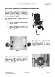
Snazzi Pushchair Workshop Manual<br />
Fixed Height<br />
Backrest<br />
Push Handle<br />
Adjustor<br />
Integrated<br />
Side pads<br />
Frame<br />
Lock<br />
Adjustable<br />
Hip Guides<br />
Tie Down<br />
Bracket<br />
Hip Belt<br />
Brake Bar<br />
Adjustable<br />
Base<br />
Knee<br />
Angle Adjustor<br />
Footplate<br />
Fig 0.1 Snazzi Pushchair Open (size 1 shown)<br />
Document No: 055-05 v3 Page 2 of 34 November 2012<br />
Snazzi Pushchair Workshop Manual.docx
Snazzi Pushchair Workshop Manual<br />
Fig 0.2 Snazzi Pushchair Folded (size 1 shown)<br />
Document No: 055-05 v3 Page 3 of 34 November 2012<br />
Snazzi Pushchair Workshop Manual.docx
Snazzi Pushchair Workshop Manual<br />
CONTENTS<br />
Item Description Page<br />
1 Your Snazzi Pushchair Workshop Manual 5 - 7<br />
2 Transit Packaging 7 - 8<br />
3 Tools & Torque Settings 8<br />
4 Preparing for use and operation 8<br />
4.1 Unfolding the frame 9<br />
4.2 Brakes 9<br />
4.3 Tilt in Space 9<br />
4.4 Seat standard adjustments 9<br />
5 Final Checks 10<br />
6 Maintenance 10<br />
6.1 Routine maintenance 10<br />
6.2 Six monthly maintenance 10-11<br />
7 Repairs 11<br />
7.1 Rear wheels 12<br />
7.2 Castor assembly and front tie down bracket 13 – 14<br />
7.3 Brake assembly 15 – 16<br />
7.4 Tilt in Space gas spring 17<br />
7.5 Locking Slider 18 – 21<br />
7.6 Hip Guides 21 – 24<br />
7.7 Footrest Parts 25<br />
7.7.1 Knee Angle Adjustors 25 – 26<br />
7.7.2 Footrest Stems 27 – 28<br />
7.7.3 Footrest Tray 29<br />
7.7.4 Footrest Slide Assembly 29<br />
7.8 Sun Canopy Assembly 30 – 33<br />
8 Cleaning 34<br />
9 Parts Lists 34<br />
Document No: 055-05 v3 Page 4 of 34 November 2012<br />
Snazzi Pushchair Workshop Manual.docx
Snazzi Pushchair Workshop Manual<br />
1: Your Snazzi Pushchair Workshop Manual<br />
The purpose of this <strong>manual</strong> is to help you get the best from your <strong>pushchair</strong>. It does this by<br />
telling you how to complete those maintenance and repair tasks that can be carried out by a<br />
competent person. The <strong>manual</strong> also tells you when you should contact the manufacturer<br />
who is:<br />
<strong>Tendercare</strong> <strong>Ltd</strong>.<br />
PO BOX 3091, Littlehampton, BN16 2WF<br />
Tel: (01903) 726161 Fax: (01903) 734083<br />
Email: info@tendercareltd.com<br />
Web: www.tendercareltd.com<br />
IMPORTANT:<br />
This <strong>manual</strong> must be read and used in conjunction with the user <strong>manual</strong>.<br />
The Snazzi is a highly adjustable <strong>pushchair</strong> designed to accommodate a wide variety of<br />
special seating needs. The <strong>pushchair</strong> is a single complete unit that folds down for easy<br />
storage. The Snazzi is available in 2 sizes.<br />
The <strong>pushchair</strong> is made of a strong and lightweight aluminium alloy, minimising weight and<br />
providing a very rugged frame. The Snazzi features a 10 o to 40 o infinitely adjustable tilt in<br />
space facility and has 2 fixed rear wheels and 2 swivelling front castors for easy<br />
manoeuvring.<br />
The integrated seat unit offers exceptional growth, thanks to its versatile design and large<br />
range of adjustment to all supports. It has an easy to remove, breathable cover, and comes<br />
supplied with a hip belt as standard.<br />
Seat adjustments (please see table below for details of adjustment ranges): Seat depth<br />
adjustment, width adjustable Hip Guides, 5 o back recline adjustment (90 o and 95 o fixed<br />
positions) large fixed back height with a range of harnessing positions, and depth & angle<br />
adjustable Footrest.<br />
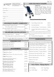
The following accessories for use with the Snazzi Pushchair are available from <strong>Tendercare</strong><br />
<strong>Ltd</strong>.<br />
Equipment carrying tray, Shopping basket, Sun / Rain-hood, Transparent Rain Shield,<br />
Fixed Lateral Supports, Height and width adjustable wrap around Lateral Supports, Butterfly<br />
chest harness, ‘H’ harness, Foot and Toe Straps, Pommel, Play Tray, Lateral Head<br />
Supports, Standard Headrest, Extra Recess Headrest, and Occipital Roll Headrest.<br />
These instructions apply to all sizes.<br />
Document No: 055-05 v3 Page 5 of 34 November 2012<br />
Snazzi Pushchair Workshop Manual.docx
Snazzi Pushchair Workshop Manual<br />
Snazzi Pushchair Adjustments<br />
Support Snazzi Pushchair Size 1 Snazzi Pushchair Size 2<br />
Tilt In Space 10 o - 40 o 10 o - 40 o<br />
Seat Depth 220 – 300 mm 280 – 360 mm<br />
Seat Width 190 – 290 mm 190 – 290 mm<br />
Backrest Height 600 mm fixed 670 mm fixed<br />
Footrest Depth 172 – 300 mm 172 – 320 mm<br />
Back Recline Angle 90° or 95 o 90 o or 95 o<br />
Knee Angle* -15°- 90° -15°- 90°<br />
Pushchair Weight 14Kg 15Kg<br />
Maximum Carry Weight** 35Kg 35Kg<br />
IMPORTANT:<br />
* Knee angle adjustable in 15° increments<br />
** Maximum carry weight includes the occupant and all accessories.<br />
Snazzi Pushchair Open<br />
Dimensions (mm)<br />
Size 1 Size 2<br />
A 780 863<br />
B 607 607<br />
C 1069 1155<br />
C<br />
A<br />
B<br />
Document No: 055-05 v3 Page 6 of 34 November 2012<br />
Snazzi Pushchair Workshop Manual.docx
Snazzi Pushchair Workshop Manual<br />
Snazzi Wheelbase Folded<br />
Dimensions (mm)<br />
Size 1 Size 2<br />
A 802 875<br />
B 607 607<br />
C 402 420<br />
C<br />
A<br />
B<br />
All sizes and weights are given as a guide. <strong>Tendercare</strong> ltd reserves the right to amend<br />
specifications at any time as part of their product development programme.<br />
2: Unpacking<br />
The <strong>pushchair</strong> is delivered in a cardboard carton. This measures 680mm wide x 480mm<br />
deep x 1030mm high and weighs approximately 16Kg (size 1) or 17Kg (size 2).<br />
WARNING:<br />
The transit carton is quite bulky so moving and unpacking must be done with care.<br />
Observe all lifting and handling regulations.<br />
Stand the carton upright making sure it is supported and cannot fall over. Open the carton<br />
and remove any packages or packing, which could obstruct the removal of the <strong>pushchair</strong>.<br />
Remove the <strong>pushchair</strong>.<br />
The carton should contain the following items:<br />
Item Component QTY. Yes No<br />
1 Size 1 or 2 Pushchair 1<br />
2 User Manual 1<br />
3 5mm Alan key 1<br />
The following items should be fitted to the seat as standard:<br />
Item Component QTY. Yes No<br />
4 Hip guide covers 2<br />
5 Seat Base Cover 1<br />
6 Seat Back Cover 1<br />
7 Hip Belt 1<br />
Document No: 055-05 v3 Page 7 of 34 November 2012<br />
Snazzi Pushchair Workshop Manual.docx
Snazzi Pushchair Workshop Manual<br />
Please note, accessories such as lateral supports or harnessing that were ordered at the<br />
same time as the <strong>pushchair</strong> will be included in the main package.<br />
Larger accessories will be packaged in separate cartons (e.g. the rain cover).<br />
IMPORTANT:<br />
If any items are damaged or missing, then please contact <strong>Tendercare</strong>, preferably by email at<br />
info@tendercareltd.com or alternatively please call us on (01903) 726161 within 36 hours of<br />
delivery.<br />
After unpacking and checking you have all components and they are in good condition<br />
dispose of the packaging at your local recycling centre. Alternatively retain and reuse.<br />
3: Tools and Torque Settings<br />
The following tools are required to dismantle, reassemble and repair the <strong>pushchair</strong>:<br />
Spanners and sockets:<br />
Hexagon Keys:<br />
Torque Wrench:<br />
Screwdrivers:<br />
7mm, 10mm, 13mm and 19mm<br />
2.5mm, 4mm, 5mm and 6mm<br />
Range 0 to 50 Nm<br />
2 small flat blade screwdrivers<br />
4: Preparing for use and operation<br />
Torque Settings<br />
Spanner Size (mm) Torque (Nm)<br />
7 5<br />
8 10<br />
10 15<br />
13 25<br />
19 50<br />
WARNING:<br />
When opening or folding the <strong>pushchair</strong>, ensure that you hold the frame so that you<br />
avoid any danger of catching your fingers in moving parts.<br />
The following pre-delivery procedures should be carried out to check that the <strong>pushchair</strong> has<br />
not suffered damage during transit and that all features operate satisfactorily. Refer to the<br />
user <strong>manual</strong> for detailed instructions on performing each action.<br />
Document No: 055-05 v3 Page 8 of 34 November 2012<br />
Snazzi Pushchair Workshop Manual.docx
Snazzi Pushchair Workshop Manual<br />
4.1 Unfolding the Frame<br />
Unfold and assemble the <strong>pushchair</strong>: Follow the instructions in section 4.1 of the user<br />
<strong>manual</strong><br />
Checks:<br />
• Make sure all joints move freely<br />
• Make sure the frame locks latch correctly<br />
• Make sure the safety catch works correctly<br />
• Check that the push handle adjustors work<br />
• Ensure that all fixings are secure and that the frame has not been bent or otherwise<br />
damaged during transit.<br />
4.2 Brakes<br />
Test the brakes: Follow the instructions in section 4.2 of the user <strong>manual</strong><br />
Checks:<br />
• Make sure the brakes work correctly<br />
• Check that the fixing bolts are secure<br />
WARNING:<br />
The break mechanism is spring loaded so care must be taken when operating it.<br />
4.3 Tilt in Space<br />
Test the tilt in space mechanism: Follow the instructions on section 4.3 of the user <strong>manual</strong>.<br />
Checks:<br />
• Make sure that the release lever is present and secure.<br />
• Check that the <strong>pushchair</strong> tilts correctly and that it will lock at any position within its<br />
range.<br />
• Check that the 2 bolts that secure the gas spring are secure.<br />
IMPORTANT:<br />
Always support the seat when tilting, as the gas springs can be quick to operate. If the seat is<br />
not supported, it may move swiftly and could cause the occupant distress.<br />
4.4 Seat standard adjustments:<br />
All adjustments to the seat are made using hand wheels, or the 5mm hexagon key<br />
provided. Test the adjustment ranges of the seat base, hip width, footrest depth, and<br />
footrest angle as detailed in sections 5.1.1 – 5.1.2 of the user <strong>manual</strong>.<br />
Checks:<br />
• Ensure all elements are free to move over their entire adjustment range (note that<br />
the cover and harnessing may need adjusting to allow this, instructions on how to<br />
adjust these are given in section 5 of the user <strong>manual</strong>)<br />
• Check that all elements lock correctly<br />
• Check that the framework is square and has not been damaged during transit.<br />
Document No: 055-05 v3 Page 9 of 34 November 2012<br />
Snazzi Pushchair Workshop Manual.docx
Snazzi Pushchair Workshop Manual<br />
5: Final checks<br />
1. Check that the pelvic strap or harness is secure and adjusted correctly.<br />
2. Check that the cover is correctly fitted.<br />
3. Ensure the safety catch is locked.<br />
6: Maintenance<br />
Should a problem be found when carrying out the regular checks, it should be immediately<br />
reported to the issuing authority or <strong>Tendercare</strong> <strong>Ltd</strong>.<br />
6.1 Routine maintenance<br />
The user’s family can easily carry out the following tasks. The supplied 5mm Allen key is<br />
required to tighten the footrest.<br />
1. Always wipe the <strong>pushchair</strong> dry. Never put it away damp.<br />
2. Check that the two M8 x 16 footrest bolts are in place and are tight by using the Allen<br />
key (daily).<br />
3. Check all nuts, bolts, and hand wheels are tight (daily)<br />
4. Check operation of the brake, folding and reclining mechanisms (weekly).<br />
5. Check condition of harnessing and stitching (weekly).<br />
6. Clean frame when necessary (we suggest at least once a week).<br />
If you find any faults refer to your issuing authority or <strong>Tendercare</strong> <strong>Ltd</strong>.<br />
6.2 Six-monthly maintenance<br />
Only someone who is a competent tradesman or repairer should carry out this work. If a<br />
major fault is found stop using the <strong>pushchair</strong> until it has been corrected.<br />
1. Fold and open the <strong>pushchair</strong>. Check that all movements through the folding range<br />
are free. Examine frame for any damage.<br />
2. Check operation of the <strong>pushchair</strong> tilt in space mechanism.<br />
3. Examine upholstery and foot straps for wear and arrange for replacement if<br />
necessary.<br />
4. Examine nuts, bolts, pivots and frame plugs for tightness and general condition.<br />
5. Examine brake assembly for wear, damage and correct operation.<br />
6. Examine tyres for sharp objects, cuts or splits.<br />
Document No: 055-05 v3 Page 10 of 34 November 2012<br />
Snazzi Pushchair Workshop Manual.docx
Snazzi Pushchair Workshop Manual<br />
7. Examine castor and wheel bearings for excessive wear.<br />
8. Check castors and rear wheels for free rotation, security and accumulation of fluff<br />
and grit. Remove any fluff and grit with a dry lint free cloth.<br />
9. Check the safety clip mechanism for proper operation.<br />
10. Check the locking sliders are working correctly and are not showing signs of wear<br />
or damage. Arrange replacements if necessary.<br />
For all other repairs refer to your issuing authority or <strong>Tendercare</strong> <strong>Ltd</strong>.<br />
7: Repairs<br />
Only an authorised repairer should carry out the following repairs.<br />
1. Repairs: For all repairs contact your issuing authority<br />
2. Major repairs: For all major repairs e.g. bent or damaged frame, the <strong>pushchair</strong><br />
should be returned to the factory. Contact <strong>Tendercare</strong> ltd, customer services on<br />
01903 726161, or email to info@tendercareltd.com<br />
3. Factory replacement components should be used in all repairs. These are available<br />
from <strong>Tendercare</strong>. Please refer to the parts lists at the end of this <strong>manual</strong> (section 10)<br />
for details of replacement parts.<br />
Important points when performing a repair:<br />
1. Do not reuse Nylock nuts, always replace with a new nut<br />
2. Always use Loctite thread locking compound grade 241 or 243 on all threads when<br />
reassembling any part of the system.<br />
3. Always use the recommended component parts available from <strong>Tendercare</strong> <strong>Ltd</strong>.<br />
4. Do not attempt to correct bent framework or perform any modifications to welded<br />
parts. If any main framework sections are bent or damaged please return the product<br />
to the factory.<br />
Document No: 055-05 v3 Page 11 of 34 November 2012<br />
Snazzi Pushchair Workshop Manual.docx
Snazzi Pushchair Workshop Manual<br />
7.1: Rear Wheels<br />
Replace if damaged or worn. To change the rear wheel:<br />
• Remove the wheel cap using a small<br />
screwdriver (see fig 7.1.1 left).<br />
• Using a 19mm spanner, undo the axle<br />
bolt and remove the wheel from the<br />
frame (see fig 7.1.2 below).<br />
Fig 7.1.1<br />
• Feed the M12 bolt through<br />
the wheel and apply some<br />
Loctite thread locking<br />
compound onto the protruding<br />
thread, then screw the bolt<br />
into the threaded bush in the<br />
frame.<br />
• Tighten to 50Nm with a<br />
torque wrench.<br />
• Finally push fit the wheel cap<br />
over the bolt head. Fig 7.1.2<br />
Document No: 055-05 v3 Page 12 of 34 November 2012<br />
Snazzi Pushchair Workshop Manual.docx
Snazzi Pushchair Workshop Manual<br />
7.2: Front Castors and Front Tie Down Bracket<br />
Replace if damaged or worn. To change the front castor:<br />
• Remove the wheel by unscrewing the<br />
M8 socket cap bolt using a 5mm<br />
hexagon key.<br />
• Next remove the castor housing using<br />
a 19mm spanner.<br />
Fig 7.2.1<br />
• To fit the new castor, first<br />
ensure the wheel is removed<br />
from its housing.<br />
• Next place the bolt through the<br />
housing and apply some Loctite<br />
thread locking compound on the<br />
protruding threads, then screw<br />
into the threaded bushing in the<br />
frame and tighten to 50Nm with<br />
a torque wrench.<br />
• Screw the new wheel into the<br />
castor housing using a 5mm<br />
hexagon key and tighten firmly<br />
(no other tool is required to fit<br />
the wheel as the castor housing<br />
includes a captive nylock nut).<br />
Fig 7.2.2<br />
Document No: 055-05 v3 Page 13 of 34 November 2012<br />
Snazzi Pushchair Workshop Manual.docx
Snazzi Pushchair Workshop Manual<br />
Fig 7.2.3<br />
• Snazzi <strong>pushchair</strong>s ordered after<br />
November 2012 come supplied with a<br />
front tie down bracket. This fits<br />
between the front castor and frame.<br />
• To replace the front tie down bracket,<br />
remove the front castor as detailed<br />
above. Slide the tie down bracket<br />
over the bolt with the loop facing the<br />
front of the <strong>pushchair</strong>, and refit the<br />
castor to the frame.<br />
• Always apply Loctite thread locking<br />
compound onto the castor bolt before<br />
refitting to the frame.<br />
Document No: 055-05 v3 Page 14 of 34 November 2012<br />
Snazzi Pushchair Workshop Manual.docx
Snazzi Pushchair Workshop Manual<br />
7.3: Brake Assembly<br />
Replace the brake bar if it is bent or damaged. The spring may also be replaced if corroded<br />
or stretched.<br />
IMPORTANT<br />
The brake system uses a high-tension torsion spring. Care must be taken when working on the<br />
brake mechanism. The following instructions are the recommended method for dismantling<br />
the brake system to safely release the tension on the spring. If you are not confident to work<br />
on this assembly please return your frame to the <strong>Tendercare</strong> factory.<br />
To dismantle the brake assembly:<br />
Fig 7.3.1<br />
• Put the break into the “off”<br />
position, and remove the<br />
torsion spring by pushing down<br />
and lifting off the chassis<br />
mounting location as shown<br />
(see fig 7.3.1).<br />
• Note that the spring is secured<br />
onto the brake bar with a star<br />
lock washer; remove this by<br />
levering off with a screw driver<br />
if the spring is to be changed.<br />
• Undo the 4 x M4 mounting bolts<br />
using a 7mm spanner and 2.5mm<br />
hexagon key (see fig 7.3.2). This<br />
will release the 2 ‘U’ lock plates<br />
and allow the brake to be<br />
removed.<br />
Fig 7.3.2<br />
Document No: 055-05 v3 Page 15 of 34 November 2012<br />
Snazzi Pushchair Workshop Manual.docx
Snazzi Pushchair Workshop Manual<br />
• To replace the brake bar, fit<br />
the brake up into the U<br />
mountings on the frame,<br />
locating the welded washers<br />
on the brake bar either side of<br />
the frame mounting point.<br />
• Slide the U Lock plate inbetween<br />
the inner welded<br />
washer and frame mounting,<br />
over the brake bar.<br />
Fig 7.3.3<br />
• Secure the lock plate in place<br />
using the M4 bolts, washer and<br />
nylock nuts.<br />
Document No: 055-05 v3 Page 16 of 34 November 2012<br />
Snazzi Pushchair Workshop Manual.docx
Snazzi Pushchair Workshop Manual<br />
7.4: Tilt in Space Gas Spring<br />
Replace the gas spring if it is damaged or worn.<br />
To remove the gas strut:<br />
• Lift the <strong>pushchair</strong> onto a<br />
suitable workbench and stand<br />
it on its wheels with the tilt<br />
angle set at minimum.<br />
• Using 2 x 13mm spanners<br />
undo the gas strut fixing bolts.<br />
Take note of the position of the<br />
washers and spacers.<br />
Fig 7.4.1<br />
• Remove the release lever; undo the<br />
release head by placing a bar (e.g.<br />
shank of a screwdriver) through the<br />
mounting hole in the head, and<br />
loosen with a 13mm spanner as<br />
shown (see fig 7.5.2).<br />
• Next, unscrew the gas spring from<br />
the head and remove the release<br />
lever.<br />
Fig 7.4.2<br />
• To reassemble the new gas<br />
spring, place the release lever<br />
into the head, and screw in the<br />
gas spring so that the pin on<br />
the end of the gas spring<br />
locates into the notch in the<br />
lever.<br />
Fig 7.4.3<br />
• Tighten until there is no<br />
movement between the pin<br />
and release lever, and then<br />
unscrew the gas spring by ¼ of<br />
a turn. This ensures that there<br />
is the correct amount of play<br />
between the pin and release<br />
lever.<br />
• Finally secure the release head by placing a bar though the mounting hole, and<br />
tighten with the 13mm spanner.<br />
Document No: 055-05 v3 Page 17 of 34 November 2012<br />
Snazzi Pushchair Workshop Manual.docx
Snazzi Pushchair Workshop Manual<br />
IMPORTANT:<br />
Ensure that there is a small amount of play between the release lever and pin on the end of the<br />
gas spring. If this is too tight, the gas spring may not lock correctly, or could have the<br />
tendency to ‘creep’ when in a locked position.<br />
7.5: Locking Slider:<br />
Replace is damaged or worn:<br />
To remove the old locking slider:<br />
Open the <strong>pushchair</strong> and place on a stable<br />
work surface, and set the safety catch on.<br />
This will ensure the frame doesn’t close up<br />
when the frame locks are removed.<br />
Using a 4mm hexagon key and a 10 mm<br />
socket or spanner, undo the M6 nylock<br />
dome nut (see Fig 7.5.1).<br />
Fig 7.5.1<br />
Taking note of the position of the bolt and<br />
washers, remove the M6 bolt from the slider<br />
(see Fig 7.5.2), this will release the tension<br />
on the spring (be careful not to allow the<br />
spring to jump out of the slider when the bolt<br />
is removed).<br />
Fig 7.5.2<br />
Document No: 055-05 v3 Page 18 of 34 November 2012<br />
Snazzi Pushchair Workshop Manual.docx
Snazzi Pushchair Workshop Manual<br />
Finally lift the slider and spring off the frame<br />
(see Fig 7.5.3).<br />
Fig 7.5.3<br />
To fit the new locking slider:<br />
1<br />
2<br />
Parts required (for one slider):<br />
1: 1 x Locking Slider<br />
2: 1 x Locking Slider Spring<br />
3: 1 x M6 Nylock Dome Nut<br />
4: 1 x M6 x 50mm Socket Button Bolt<br />
5: 2 x M6 Form A Washers<br />
3<br />
4<br />
5<br />
Fig 7.5.4<br />
First, place the spring inside the locking<br />
slider so it sits against the support splines as<br />
shown (see Fig 7.5.5).<br />
Fig 7.5.5<br />
Document No: 055-05 v3 Page 19 of 34 November 2012<br />
Snazzi Pushchair Workshop Manual.docx
Snazzi Pushchair Workshop Manual<br />
Place the slider and spring onto the frame<br />
locking point so that the slider is in the fully<br />
‘locked position’ (the frame hole will be at<br />
the top of the slot in the slider, as shown in<br />
Fig 7.5.6). Note that once the slider has<br />
been removed the frame may close up a<br />
little making it difficult to fit the new slider. If<br />
this is the case, pull the front and rear<br />
frames towards each other and the slider<br />
should drop down easily.<br />
Fig 7.5.6<br />
Next, take the M6 x 50mm socket button bolt<br />
and place one of the form A washers onto it<br />
as shown (see Fig 7.5.7).<br />
Fig 7.5.7<br />
Place the hexagon key though the slot in the<br />
slider in-between the spring coils, and pull<br />
the spring back down the slot so that the<br />
fixing hole is clear (see Fig 7.5.8). Please<br />
note if it is not possible to pull the spring<br />
back far enough, lift the slider off of the<br />
frame, rotate the spring a little and try again<br />
(rotating the spring will expose different<br />
parts of the coil- rotate until a section of coil<br />
is visible that is close to the top of the slot,<br />
this will allow the spring to be compressed<br />
far enough to clear the hole).<br />
Fig 7.5.8<br />
Document No: 055-05 v3 Page 20 of 34 November 2012<br />
Snazzi Pushchair Workshop Manual.docx
Snazzi Pushchair Workshop Manual<br />
Whilst still holding the spring back, push the<br />
M6 bolt and washer through the slider and<br />
mounting hole in the frame with the bolt<br />
head to the inside. Ensure that the bolt is<br />
above the spring and not going through the<br />
coils as shown (see Fig 7.5.9). The bolt<br />
provides the edge for the spring to work<br />
against.<br />
Fig 7.5.9<br />
Place the other washer and the M6 Nylock<br />
dome nut onto the other end of the bolt.<br />
Tighten using the 4mm hexagon key and<br />
10mm socket to the point that the bolt<br />
threads are into the nylon insert inside the<br />
dome nut (when the thread engages with the<br />
insert the force required to tighten the nut<br />
will increase), but leaving enough slack that<br />
both washers are still free to turn (see Fig<br />
7.5.10).<br />
Release the safety catch and test the locking<br />
mechanism as described in the user <strong>manual</strong>. Fig 7.5.10<br />
7.6: Hip Guides:<br />
Replace the hip guide plates if damaged or worn.<br />
First, prepare the seat by removing the hip guide covers, the seat base cover and any<br />
harnesses fitted to the seat (e.g. pelvic strap). It is not necessary to remove the back cover<br />
or any harnessing fitted to the backrest. For details of how to remove the covers, please<br />
refer to the relevant section in the Snazzi Pushchair user <strong>manual</strong>.<br />
Document No: 055-05 v3 Page 21 of 34 November 2012<br />
Snazzi Pushchair Workshop Manual.docx
Snazzi Pushchair Workshop Manual<br />
Once the covers are removed, adjust the<br />
footrest knee angle so that the footrest<br />
stems sit in line with the seat as shown (see<br />
Fig 7.6.1). For details on adjusting the<br />
footrest knee angle please refer to the user<br />
<strong>manual</strong>.<br />
Fig 7.6.1<br />
Next, fold the foot plate flat as shown (see<br />
Fig 7.6.2).<br />
Fig 7.6.2<br />
Fold the entire seat section up to reveal the<br />
underside of the seat as shown (see Fig<br />
7.6.3). Make sure the 4 thumb screws are<br />
tight (to prevent the coach bolt turning), then<br />
using a 13mm socket or spanner remove the<br />
4 nylock dome nuts.<br />
Fig 7.6.3<br />
Document No: 055-05 v3 Page 22 of 34 November 2012<br />
Snazzi Pushchair Workshop Manual.docx
Snazzi Pushchair Workshop Manual<br />
Next, remove the 4 thumbscrews and set<br />
aside (see Figs 7.6.4 and 7.6.5).<br />
Fig 7.6.4<br />
Fig 7.6.5, Left: The seat base with the 4<br />
thumbscrews removed.<br />
Fig 7.6.5<br />
Fold the seat base back down to its normal<br />
position; remove the 4 coach bolts (see<br />
arrows, Fig 7.6.6) holding the hip guides<br />
onto the base.<br />
Fig 7.6.6<br />
Document No: 055-05 v3 Page 23 of 34 November 2012<br />
Snazzi Pushchair Workshop Manual.docx
Snazzi Pushchair Workshop Manual<br />
Finally remove the hip guides. When fitting<br />
the new hip guides be careful to take note of<br />
the position of the 4 black spacer washers<br />
(see arrows, Fig 7.6.7), ensuring that they<br />
line up with the mounting holes in the base<br />
plate. Also make sure the slots in the upper<br />
base plate line up with the front mounting<br />
holes.<br />
Fig 7.6.7<br />
• Next, place the new hip guides on top of the upper base plate and washers so that<br />
the lateral slots in the hip guides line up with the holes in the washers, lower base<br />
plate and base holes.<br />
• Secure the new hip guides in place by placing the coach bolts through the hip guide<br />
slots, upper base slots / washers and base mounting holes. With the seat in the flat<br />
position, secure the bolts in place using the 4 thumbscrews.<br />
• Tighten the screws, then place 4 M8 nylock nuts onto the end of the threads of the<br />
coach bolts to prevent the thumbscrews being lost. Tighten the nuts to the point that<br />
the screw threads are into the nylon insert, but so that there is still sufficient free<br />
thread on coach bolts that the thumbscrews can be undone to adjust the hip guides<br />
and seat depth.<br />
• Finally re-attach any covers or harnessing removed (for details on fitting the covers<br />
and harnesses please refer to the user <strong>manual</strong>).<br />
Document No: 055-05 v3 Page 24 of 34 November 2012<br />
Snazzi Pushchair Workshop Manual.docx
Snazzi Pushchair Workshop Manual<br />
7.7: Footrest Parts:<br />
If a complete footrest assembly is ordered, it comes supplied with footrest slide with the tray<br />
pre-assembled, footrest stems and the angle adjustors. For information on fitting these<br />
please refer to the instructions given in section 7.7.1 (for the angle adjustors), and 7.7.2 (for<br />
the stems) and 7.7.4 (for the slide and tray assembly) below.<br />
7.7.1: Knee Angle Adjustors:<br />
To replace the knee angle adjustors:<br />
First remove the M5 bolt securing the<br />
footrest stems into the adjustors using a<br />
3mm hexagon key and 8mm socket or<br />
spanner as shown (see Fig 7.7.1.1). Take<br />
note of the position of the washers.<br />
Fig 7.7.1.1<br />
Take the footrest stems (complete with the<br />
footrest and slide) out from the adjustors and<br />
set aside.<br />
Fig 7.7.1.2<br />
Document No: 055-05 v3 Page 25 of 34 November 2012<br />
Snazzi Pushchair Workshop Manual.docx
Snazzi Pushchair Workshop Manual<br />
Fig 7.7.1.3 Right: The adjustors with the<br />
footrest and stems removed.<br />
Fig 7.7.1.3<br />
Fold the seat base up to get easy access to<br />
the underside of the seat. Using a 3mm<br />
hexagon key and an 8mm socket or spanner<br />
remove the M5 bolt securing the back of the<br />
angle adjustor as shown (see Fig 7.7.1.4).<br />
Take note of the position of the washers.<br />
Fig 7.7.1.4<br />
Document No: 055-05 v3 Page 26 of 34 November 2012<br />
Snazzi Pushchair Workshop Manual.docx
Snazzi Pushchair Workshop Manual<br />
Fig 7.7.1.5 Right: The seat base poles with<br />
the adjustor removed.<br />
When fitting the new adjustors, ensure that<br />
the release buttons are facing towards the<br />
outsides, and refit with new Nylock dome<br />
nuts- do not reuse Nylock nuts.<br />
Fig 7.7.1.5<br />
7.7.2: Footrest Stems:<br />
To replace the footrest stems:<br />
Set the footrest knee angle so that the<br />
footrest stems are in line with the seat, and<br />
fold the footplate flat against the stems (for<br />
more details on adjusting the footrest and<br />
knee angle please refer to the user <strong>manual</strong>).<br />
Fold the footrest and seat base up to provide<br />
access to the back of the footrest stems.<br />
Using a screwdriver remove the 2 selftapping<br />
screws from the bottom of the<br />
footrest stems as shown (see Fig 7.7.2.1).<br />
Fig 7.7.2.1<br />
Document No: 055-05 v3 Page 27 of 34 November 2012<br />
Snazzi Pushchair Workshop Manual.docx
Snazzi Pushchair Workshop Manual<br />
Next, undo the 2 M8 locking bolts on the<br />
footrest slide using a 5mm hexagon key (see<br />
Fig 7.7.2.2).<br />
Slide the footrest slide assembly off of the<br />
footrest stems.<br />
Fig 7.7.2.2<br />
Finally, undo the M5 bolt securing the<br />
footrest stem to the knee angle adjustor<br />
using a 3mm hexagon key and 8mm socket<br />
or spanner as shown (see Fig 7.7.2.3). Take<br />
note of the position of the washers.<br />
Fig 7.7.2.3<br />
To fit the new stems: Follow the reverse of this procedure, and fit with a new Nylock dome<br />
nut (never re-use Nylock nuts).<br />
Document No: 055-05 v3 Page 28 of 34 November 2012<br />
Snazzi Pushchair Workshop Manual.docx
Snazzi Pushchair Workshop Manual<br />
7.7.3: Footrest Tray:<br />
Replace if damaged or worn:<br />
Set the knee angle to 45 degrees as shown<br />
(see fig 7.7.3.1). For more details of how to<br />
adjust the footrest knee angle please refer to<br />
the user <strong>manual</strong>.<br />
Fig 7.7.3.1<br />
Using a 5mm hexagon key and a 13mm<br />
socket or spanner remove the M8<br />
countersunk bolts that secure the footrest<br />
tray to the footrest slide as shown (see Fig<br />
7.7.3.2). Take note of the position of the<br />
washers.<br />
Fig 7.7.3.2<br />
To fit the new tray, attach it to the footrest slide using the countersunk bolts and washers<br />
removed from the old tray. Secure with new Nylock dome nuts, do not reuse Nylock nuts.<br />
7.7.4: Footrest Slide Assembly:<br />
The footrest slide assembly will come pre-assembled complete with the plastic tray. To fit<br />
the new assembly, simply remove the old slide assembly following the instructions given in<br />
section 7.7.2 above. Slide the new assembly onto the footrest stems and secure back in<br />
place.<br />
Document No: 055-05 v3 Page 29 of 34 November 2012<br />
Snazzi Pushchair Workshop Manual.docx
Snazzi Pushchair Workshop Manual<br />
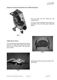
7.8: Sun Canopy Assembly:<br />
The following instructions detail how to fully assemble the sun canopy including the cover.<br />
A separate parts list “Snazzi Sun Hood Parts List” is available on our website should any<br />
parts need to be replaced.<br />
1 2 3<br />
4 5 6<br />
Left: The sun canopy adjustor parts:<br />
1: Large Teeth Adjustor<br />
2: Small Teeth Adjustor<br />
3: Sun Canopy Insert Piece<br />
4: M5 Knurled Thumbscrew<br />
5: M5 x 25 mm Coach Bolt<br />
6: Sun Canopy Spring<br />
Fig 7.8.1<br />
Front Bar<br />
To assemble the sun canopy, lay out the 2<br />
frame bars and adjustor parts as shown (see<br />
Fig 7.8.2, right).<br />
Rear Bar<br />
Fig 7.8.2<br />
Document No: 055-05 v3 Page 30 of 34 November 2012<br />
Snazzi Pushchair Workshop Manual.docx
Snazzi Pushchair Workshop Manual<br />
Take the front bar and feed into the front<br />
fitting tube in the cover as shown (see fig<br />
7.8.3, right).<br />
Fig 7.8.3<br />
Left: The front frame bar fitted to the cover<br />
(see Fig 7.8.4).<br />
Fig 7.8.4<br />
Next, take the rear bar and feed into the rear<br />
fitting tube as shown (see fig 7.8.5, right).<br />
Fig 7.8.5<br />
Document No: 055-05 v3 Page 31 of 34 November 2012<br />
Snazzi Pushchair Workshop Manual.docx
Snazzi Pushchair Workshop Manual<br />
Left: The rear bar fitted into the cover (see<br />
Fig 7.8.6).<br />
Fig 7.8.6<br />
Next, fit the ‘large teeth’ canopy adjustor<br />
onto the end of the front bar as shown (see<br />
Fig 7.8.7, right). Push the adjustor onto the<br />
end of the rod until the hole in the adjustor<br />
lines up with the square cut out in the end of<br />
the rod.<br />
Fig 7.8.7<br />
Take the coach bolt and push it through the<br />
frame bar and adjustor so that the square<br />
neck of the bolt fits into the square cut out in<br />
the bar. Take the spring and push onto the<br />
other end of the bolt so that the large end of<br />
the spring fits over the mounting point on the<br />
adjustor as shown (see Fig 7.8.8, left).<br />
Fig 7.8.8<br />
Document No: 055-05 v3 Page 32 of 34 November 2012<br />
Snazzi Pushchair Workshop Manual.docx
Snazzi Pushchair Workshop Manual<br />
Take the frame fixing bracket and fit onto the<br />
end of the bolt as shown (see Fig 7.8.9,<br />
right). Note the brackets are handed and will<br />
only fit one way around. Make sure the<br />
correct hand is used so that the large teeth<br />
on the bracket and plastic adjustor line up.<br />
Fig 7.8.9<br />
Take the ‘small teeth’ adjustor and fit over<br />
the end of the bolt. Thread the rear bar over<br />
the bolt so that it sits into the recess in the<br />
small teeth adjustor, and then secure with<br />
the thumb screw as shown (see Fig 7.8.10,<br />
left).<br />
Fig 7.8.10<br />
To dismantle the sun canopy follow the reverse of these instructions.<br />
Document No: 055-05 v3 Page 33 of 34 November 2012<br />
Snazzi Pushchair Workshop Manual.docx
Snazzi Pushchair Workshop Manual<br />
8: Cleaning<br />
1. To clean the wheelbase or interface, wipe with a damp cloth and dry thoroughly.<br />
2. For more stubborn stains wipe with a damp cloth and warm water in which a little<br />
mild soap has been dissolved. Dry thoroughly.<br />
3. Never use furniture polish or any spirit to clean the frame.<br />
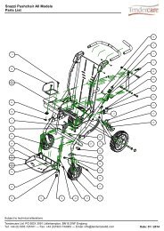
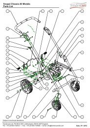
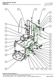
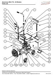
9: Parts Lists<br />
Please refer to the parts list / exploded diagram for ordering information of any parts<br />
needed for the Snazzi. The parts list is available on the website as;<br />
• ‘Snazzi Pushchair Parts List’ (applies to both sizes of <strong>pushchair</strong>).<br />
• ‘Snazzi Sun Hood Parts List’ (applies to both sizes of <strong>pushchair</strong>)<br />
Document No: 055-05 v3 Page 34 of 34 November 2012<br />
Snazzi Pushchair Workshop Manual.docx