snazzi pushchair workshop manual - Tendercare Ltd
snazzi pushchair workshop manual - Tendercare Ltd
snazzi pushchair workshop manual - Tendercare Ltd

You also want an ePaper? Increase the reach of your titles
YUMPU automatically turns print PDFs into web optimized ePapers that Google loves.
Snazzi Pushchair Workshop ManualSnazzi ® PushchairWORKSHOP MANUALIMPORTANTPlease read these instructions carefullybefore attempting to maintain the <strong>pushchair</strong>Document No: 055-05 v1b Page 1 of 29 August 2012Snazzi Pushchair Workshop Manual.docx
Snazzi Pushchair Workshop ManualFixed HeightBackrestPush HandleAdjustorIntegratedSide padsFrameLockAdjustableHip GuidesTie DownBracketHip BeltBrake BarAdjustableBaseKneeAngle AdjustorFootplateFig 0.1 Snazzi Pushchair Open (size 1 shown)Document No: 055-05 v1b Page 2 of 29 August 2012Snazzi Pushchair Workshop Manual.docx
Snazzi Pushchair Workshop ManualFig 0.2 Snazzi Pushchair Folded (size 1 shown)Document No: 055-05 v1b Page 3 of 29 August 2012Snazzi Pushchair Workshop Manual.docx
Snazzi Pushchair Workshop ManualCONTENTSItem Description Page1 Your Snazzi Pushchair Workshop Manual 5 - 72 Transit Packaging 7 - 83 Tools & Torque Settings 84 Preparing for use and operation 84.1 Unfolding the frame 94.2 Brakes 94.3 Tilt in Space 94.4 Seat standard adjustments 95 Final Checks 106 Maintenance 106.1 Routine maintenance 106.2 Six monthly maintenance 10-117 Repairs 117.1 Rear wheels 127.2 Castor assembly 137.3 Brake assembly 14 - 157.4 Tilt in Space gas spring 167.5 Locking Slider 17 - 207.6 Hip Guides 20 – 237.7 Footrest Parts 247.7.1 Knee Angle Adjustors 24 – 257.7.2 Footrest Stems 26 – 277.7.3 Footrest Tray 287.7.4 Footrest Slide Assembly 288 Cleaning 299 Parts Lists 29Document No: 055-05 v1b Page 4 of 29 August 2012Snazzi Pushchair Workshop Manual.docx
Snazzi Pushchair Workshop Manual1: Your Snazzi Pushchair Workshop ManualThe purpose of this <strong>manual</strong> is to help you get the best from your <strong>pushchair</strong>. It does this bytelling you how to complete those maintenance and repair tasks that can be carried out by acompetent person. The <strong>manual</strong> also tells you when you should contact the manufacturerwho is:<strong>Tendercare</strong> <strong>Ltd</strong>.PO BOX 3091, Littlehampton, BN16 2WFTel: (01903) 726161 Fax: (01903) 734083Email: info@tendercareltd.comWeb: www.tendercareltd.comIMPORTANT:This <strong>manual</strong> must be read and used in conjunction with the user <strong>manual</strong>.The Snazzi is a highly adjustable <strong>pushchair</strong> designed to accommodate a wide variety ofspecial seating needs. The <strong>pushchair</strong> is a single complete unit that folds down for easystorage. The Snazzi is available in 2 sizes.The <strong>pushchair</strong> is made of a strong and lightweight aluminium alloy, minimising weight andproviding a very rugged frame. The Snazzi features a 10 o to 40 o infinitely adjustable tilt inspace facility and has 2 fixed rear wheels and 2 swivelling front castors for easymanoeuvring.The integrated seat unit offers exceptional growth, thanks to its versatile design and largerange of adjustment to all supports. It has an easy to remove, breathable cover, and comessupplied with a hip belt as standard.Seat adjustments (please see table below for details of adjustment ranges): Seat depthadjustment, width adjustable Hip Guides, 5 o back recline adjustment (90 o and 95 o fixedpositions) large fixed back height with a range of harnessing positions, and depth & angleadjustable Footrest.The following accessories for use with the Snazzi Pushchair are available from <strong>Tendercare</strong><strong>Ltd</strong>.Equipment carrying tray, Shopping basket, Sun / Rain-hood, Transparent Rain Shield,Fixed Lateral Supports, Height and width adjustable wrap around Lateral Supports, Butterflychest harness, ‘H’ harness, Foot and Toe Straps, Pommel, Play Tray, Lateral HeadSupports, Standard Headrest, Extra Recess Headrest, and Occipital Roll Headrest.These instructions apply to all sizes.Document No: 055-05 v1b Page 5 of 29 August 2012Snazzi Pushchair Workshop Manual.docx
Snazzi Pushchair Workshop ManualSnazzi Pushchair AdjustmentsSupport Snazzi Pushchair Size 1 Snazzi Pushchair Size 2Tilt In Space 10 o - 40 o 10 o - 40 oSeat Depth 220 – 300 mm 280 – 360 mmSeat Width 190 – 290 mm 190 – 290 mmBackrest Height 600 mm fixed 670 mm fixedFootrest Depth 172 – 300 mm 172 – 320 mmBack Recline Angle 90° or 95 o 90 o or 95 oKnee Angle* -15°- 90° -15°- 90°Pushchair Weight 14Kg 15KgMaximum Carry Weight** 35Kg 35KgIMPORTANT:* Knee angle adjustable in 15° increments** Maximum carry weight includes the occupant and all accessories.Snazzi Pushchair OpenDimensions (mm)Size 1 Size 2A 780 863B 607 607C 1069 1155CABDocument No: 055-05 v1b Page 6 of 29 August 2012Snazzi Pushchair Workshop Manual.docx
Snazzi Pushchair Workshop ManualSnazzi Wheelbase FoldedDimensions (mm)Size 1 Size 2A 802 875B 607 607C 402 420CABAll sizes and weights are given as a guide. <strong>Tendercare</strong> ltd reserves the right to amendspecifications at any time as part of their product development programme.2: UnpackingThe <strong>pushchair</strong> is delivered in a cardboard carton. This measures 680mm wide x 480mmdeep x 1030mm high and weighs approximately 16Kg (size 1) or 17Kg (size 2).WARNING:The transit carton is quite bulky so moving and unpacking must be done with care.Observe all lifting and handling regulations.Stand the carton upright making sure it is supported and cannot fall over. Open the cartonand remove any packages or packing, which could obstruct the removal of the <strong>pushchair</strong>.Remove the <strong>pushchair</strong>.The carton should contain the following items:Item Component QTY. Yes No1 Size 1 or 2 Pushchair 12 User Manual 13 5mm Alan key 1The following items should be fitted to the seat as standard:Item Component QTY. Yes No4 Hip guide covers 25 Seat Base Cover 16 Seat Back Cover 17 Hip Belt 1Document No: 055-05 v1b Page 7 of 29 August 2012Snazzi Pushchair Workshop Manual.docx
Snazzi Pushchair Workshop ManualPlease note, accessories such as lateral supports or harnessing that were ordered at thesame time as the <strong>pushchair</strong> will be included in the main package.Larger accessories will be packaged in separate cartons (e.g. the rain cover).IMPORTANT: If any items are damaged or missing, then please contact <strong>Tendercare</strong>, preferably by email atinfo@tendercareltd.com or alternatively please call us on (01903) 726161 within 36 hours ofdelivery.After unpacking and checking you have all components and they are in good conditiondispose of the packaging at your local recycling centre. Alternatively retain and reuse.3: Tools and Torque SettingsThe following tools are required to dismantle, reassemble and repair the <strong>pushchair</strong>:Spanners and sockets:Hexagon Keys:Torque Wrench:Screwdrivers:7mm, 10mm, 13mm and 19mm2.5mm, 4mm, 5mm and 6mmRange 0 to 50 Nm2 small flat blade screwdrivers4: Preparing for use and operationTorque SettingsSpanner Size (mm) Torque (Nm)7 510 1513 2519 50WARNING:When opening or folding the <strong>pushchair</strong>, ensure that you hold the frame so that youavoid any danger of catching your fingers in moving parts.The following pre-delivery procedures should be carried out to check that the <strong>pushchair</strong> hasnot suffered damage during transit and that all features operate satisfactorily. Refer to theuser <strong>manual</strong> for detailed instructions on performing each action.Document No: 055-05 v1b Page 8 of 29 August 2012Snazzi Pushchair Workshop Manual.docx
Snazzi Pushchair Workshop Manual4.1 Unfolding the FrameUnfold and assemble the <strong>pushchair</strong>: Follow the instructions in section 4.1 of the user<strong>manual</strong>Checks:• Make sure all joints move freely• Make sure the frame locks latch correctly• Make sure the safety catch works correctly• Check that the push handle adjustors work• Ensure that all fixings are secure and that the frame has not been bent or otherwisedamaged during transit.4.2 BrakesTest the brakes: Follow the instructions in section 4.2 of the user <strong>manual</strong>Checks:• Make sure the brakes work correctly• Check that the fixing bolts are secureWARNING:The break mechanism is spring loaded so care must be taken when operating it.4.3 Tilt in SpaceTest the tilt in space mechanism: Follow the instructions on section 4.3 of the user <strong>manual</strong>.Checks:• Make sure that the release lever is present and secure.• Check that the <strong>pushchair</strong> tilts correctly and that it will lock at any position within itsrange.• Check that the 2 bolts that secure the gas spring are secure.IMPORTANT: Always support the seat when tilting, as the gas springs can be quick to operate. If the seat isnot supported, it may move swiftly and could cause the occupant distress.4.4 Seat standard adjustments:All adjustments to the seat are made using hand wheels, or the 5mm hexagon keyprovided. Test the adjustment ranges of the seat base, hip width, footrest depth, andfootrest angle as detailed in sections 5.1.1 – 5.1.2 of the user <strong>manual</strong>.Checks:• Ensure all elements are free to move over their entire adjustment range (note thatthe cover and harnessing may need adjusting to allow this, instructions on how toadjust these are given in section 5 of the user <strong>manual</strong>)• Check that all elements lock correctly• Check that the framework is square and has not been damaged during transit.Document No: 055-05 v1b Page 9 of 29 August 2012Snazzi Pushchair Workshop Manual.docx
Snazzi Pushchair Workshop Manual5: Final checks1. Check that the pelvic strap or harness is secure and adjusted correctly.2. Check that the cover is correctly fitted.3. Ensure the safety catch is locked.6: MaintenanceShould a problem be found when carrying out the regular checks, it should be immediatelyreported to the issuing authority or <strong>Tendercare</strong> <strong>Ltd</strong>.6.1 Routine maintenanceThe user’s family can easily carry out the following tasks. The supplied 5mm Allen key isrequired to tighten the footrest.1. Always wipe the <strong>pushchair</strong> dry. Never put it away damp.2. Check that the two M8 x 16 footrest bolts are in place and are tight by using the Allenkey (daily).3. Check all nuts, bolts, and hand wheels are tight (daily)4. Check operation of the brake, folding and reclining mechanisms (weekly).5. Check condition of harnessing and stitching (weekly).6. Clean frame when necessary (we suggest at least once a week).If you find any faults refer to your issuing authority or <strong>Tendercare</strong> <strong>Ltd</strong>.6.2 Six-monthly maintenanceOnly someone who is a competent tradesman or repairer should carry out this work. If amajor fault is found stop using the <strong>pushchair</strong> until it has been corrected.1. Fold and open the <strong>pushchair</strong>. Check that all movements through the folding rangeare free. Examine frame for any damage.2. Check operation of the <strong>pushchair</strong> tilt in space mechanism.3. Examine upholstery and foot straps for wear and arrange for replacement ifnecessary.4. Examine nuts, bolts, pivots and frame plugs for tightness and general condition.5. Examine brake assembly for wear, damage and correct operation.6. Examine tyres for sharp objects, cuts or splits.Document No: 055-05 v1b Page 10 of 29 August 2012Snazzi Pushchair Workshop Manual.docx
Snazzi Pushchair Workshop Manual7. Examine castor and wheel bearings for excessive wear.8. Check castors and rear wheels for free rotation, security and accumulation of fluffand grit. Remove any fluff and grit with a dry lint free cloth.9. Check the safety clip mechanism for proper operation.10. Check the locking sliders are working correctly and are not showing signs of wearor damage. Arrange replacements if necessary.For all other repairs refer to your issuing authority or <strong>Tendercare</strong> <strong>Ltd</strong>.7: RepairsOnly an authorised repairer should carry out the following repairs.1. Repairs: For all repairs contact your issuing authority2. Major repairs: For all major repairs e.g. bent or damaged frame, the <strong>pushchair</strong>should be returned to the factory. Contact <strong>Tendercare</strong> ltd, customer services on01903 726161, or email to info@tendercareltd.com3. Factory replacement components should be used in all repairs. These are availablefrom <strong>Tendercare</strong>. Please refer to the parts lists at the end of this <strong>manual</strong> (section 10)for details of replacement parts.Important points when performing a repair:1. Do not reuse Nylock nuts, always replace with a new nut2. Always use Loctite thread locking compound grade 241 or 243 on all threads whenreassembling any part of the system.3. Always use the recommended component parts available from <strong>Tendercare</strong> <strong>Ltd</strong>.4. Do not attempt to correct bent framework or perform any modifications to weldedparts. If any main framework sections are bent or damaged please return the productto the factory.Document No: 055-05 v1b Page 11 of 29 August 2012Snazzi Pushchair Workshop Manual.docx
Snazzi Pushchair Workshop Manual7.1: Rear WheelsReplace if damaged or worn. To change the rear wheel:• Remove the wheel cap using a smallscrewdriver (see fig 7.1.1 left).• Using a 19mm spanner, undo the axlebolt and remove the wheel from theframe (see fig 7.1.2 below).Fig 7.1.1• Feed the M12 bolt throughthe wheel and apply someLoctite thread lockingcompound onto the protrudingthread, then screw the boltinto the threaded bush in theframe.• Tighten to 50Nm with atorque wrench.• Finally push fit the wheel capover the bolt head. Fig 7.1.2Document No: 055-05 v1b Page 12 of 29 August 2012Snazzi Pushchair Workshop Manual.docx
Snazzi Pushchair Workshop Manual7.2: Front CastorsReplace if damaged or worn. To change the front castor:• Remove the wheel by unscrewing theM8 socket cap bolt using a 5mmhexagon key.• Next remove the castor housing usinga 19mm spanner.Fig 7.2.1• To fit the new castor, firstensure the wheel is removedfrom its housing.• Next place the bolt through thehousing and apply some Loctitethread locking compound on theprotruding threads, then screwinto the threaded bushing in theframe and tighten to 50Nm witha torque wrench.• Screw the new wheel into thecastor housing using a 5mmhexagon key and tighten firmly(no other tool is required to fitthe wheel as the castor housingincludes a captive nylock nut).Fig 7.2.2Document No: 055-05 v1b Page 13 of 29 August 2012Snazzi Pushchair Workshop Manual.docx
Snazzi Pushchair Workshop Manual7.3: Brake AssemblyReplace the brake bar if it is bent or damaged. The spring may also be replaced if corrodedor stretched.IMPORTANT The brake system uses a high-tension torsion spring. Care must be taken when working on thebrake mechanism. The following instructions are the recommended method for dismantlingthe brake system to safely release the tension on the spring. If you are not confident to workon this assembly please return your frame to the <strong>Tendercare</strong> factory.To dismantle the brake assembly:Fig 7.3.1• Put the break into the “off”position, and remove thetorsion spring by pushing downand lifting off the chassismounting location as shown(see fig 7.3.1).• Note that the spring is securedonto the brake bar with a starlock washer; remove this bylevering off with a screw driverif the spring is to be changed.• Undo the 4 x M4 mounting boltsusing a 7mm spanner and 2.5mmhexagon key (see fig 7.3.2). Thiswill release the 2 ‘U’ lock platesand allow the brake to beremoved.Fig 7.3.2Document No: 055-05 v1b Page 14 of 29 August 2012Snazzi Pushchair Workshop Manual.docx
Snazzi Pushchair Workshop Manual• To replace the brake bar, fitthe brake up into the Umountings on the frame,locating the welded washerson the brake bar either side ofthe frame mounting point.• Slide the U Lock plate inbetweenthe inner weldedwasher and frame mounting,over the brake bar.Fig 7.3.3• Secure the lock plate in placeusing the M4 bolts, washer andnylock nuts.Document No: 055-05 v1b Page 15 of 29 August 2012Snazzi Pushchair Workshop Manual.docx
Snazzi Pushchair Workshop Manual7.4: Tilt in Space Gas SpringReplace the gas spring if it is damaged or worn.To remove the gas strut:• Lift the <strong>pushchair</strong> onto asuitable workbench and standit on its wheels with the tiltangle set at minimum.• Using 2 x 13mm spannersundo the gas strut fixing bolts.Take note of the position of thewashers and spacers.Fig 7.4.1• Remove the release lever; undo therelease head by placing a bar (e.g.shank of a screwdriver) through themounting hole in the head, andloosen with a 13mm spanner asshown (see fig 7.5.2).• Next, unscrew the gas spring fromthe head and remove the releaselever.Fig 7.4.2• To reassemble the new gasspring, place the release leverinto the head, and screw in thegas spring so that the pin onthe end of the gas springlocates into the notch in thelever.Fig 7.4.3• Tighten until there is nomovement between the pinand release lever, and thenunscrew the gas spring by ¼ ofa turn. This ensures that thereis the correct amount of playbetween the pin and releaselever.• Finally secure the release head by placing a bar though the mounting hole, andtighten with the 13mm spanner.Document No: 055-05 v1b Page 16 of 29 August 2012Snazzi Pushchair Workshop Manual.docx
Snazzi Pushchair Workshop ManualIMPORTANT: Ensure that there is a small amount of play between the release lever and pin on the end of thegas spring. If this is too tight, the gas spring may not lock correctly, or could have thetendency to ‘creep’ when in a locked position.7.5: Locking Slider:Replace is damaged or worn:To remove the old locking slider:Open the <strong>pushchair</strong> and place on a stablework surface, and set the safety catch on.This will ensure the frame doesn’t close upwhen the frame locks are removed.Using a 4mm hexagon key and a 10 mmsocket or spanner, undo the M6 nylockdome nut (see Fig 7.5.1).Fig 7.5.1Taking note of the position of the bolt andwashers, remove the M6 bolt from the slider(see Fig 7.5.2), this will release the tensionon the spring (be careful not to allow thespring to jump out of the slider when the boltis removed).Fig 7.5.2Document No: 055-05 v1b Page 17 of 29 August 2012Snazzi Pushchair Workshop Manual.docx
Snazzi Pushchair Workshop ManualFinally lift the slider and spring off the frame(see Fig 7.5.3).Fig 7.5.3To fit the new locking slider:12Parts required (for one slider):1: 1 x Locking Slider2: 1 x Locking Slider Spring3: 1 x M6 Nylock Dome Nut4: 1 x M6 x 50mm Socket Button Bolt5: 2 x M6 Form A Washers345Fig 7.5.4First, place the spring inside the lockingslider so it sits against the support splines asshown (see Fig 7.5.5).Fig 7.5.5Document No: 055-05 v1b Page 18 of 29 August 2012Snazzi Pushchair Workshop Manual.docx
Snazzi Pushchair Workshop ManualPlace the slider and spring onto the framelocking point so that the slider is in the fully‘locked position’ (the frame hole will be atthe top of the slot in the slider, as shown inFig 7.5.6). Note that once the slider hasbeen removed the frame may close up alittle making it difficult to fit the new slider. Ifthis is the case, pull the front and rearframes towards each other and the slidershould drop down easily.Fig 7.5.6Next, take the M6 x 50mm socket button boltand place one of the form A washers onto itas shown (see Fig 7.5.7).Fig 7.5.7Place the hexagon key though the slot in theslider in-between the spring coils, and pullthe spring back down the slot so that thefixing hole is clear (see Fig 7.5.8). Pleasenote if it is not possible to pull the springback far enough, lift the slider off of theframe, rotate the spring a little and try again(rotating the spring will expose differentparts of the coil- rotate until a section of coilis visible that is close to the top of the slot,this will allow the spring to be compressedfar enough to clear the hole).Fig 7.5.8Document No: 055-05 v1b Page 19 of 29 August 2012Snazzi Pushchair Workshop Manual.docx
Snazzi Pushchair Workshop ManualWhilst still holding the spring back, push theM6 bolt and washer through the slider andmounting hole in the frame with the bolthead to the inside. Ensure that the bolt isabove the spring and not going through thecoils as shown (see Fig 7.5.9). The boltprovides the edge for the spring to workagainst.Fig 7.5.9Place the other washer and the M6 Nylockdome nut onto the other end of the bolt.Tighten using the 4mm hexagon key and10mm socket to the point that the boltthreads are into the nylon insert inside thedome nut (when the thread engages with theinsert the force required to tighten the nutwill increase), but leaving enough slack thatboth washers are still free to turn (see Fig7.5.10).Release the safety catch and test the lockingmechanism as described in the user <strong>manual</strong>. Fig 7.5.107.6: Hip Guides:Replace the hip guide plates if damaged or worn.First, prepare the seat by removing the hip guide covers, the seat base cover and anyharnesses fitted to the seat (e.g. pelvic strap). It is not necessary to remove the back coveror any harnessing fitted to the backrest. For details of how to remove the covers, pleaserefer to the relevant section in the Snazzi Pushchair user <strong>manual</strong>.Document No: 055-05 v1b Page 20 of 29 August 2012Snazzi Pushchair Workshop Manual.docx
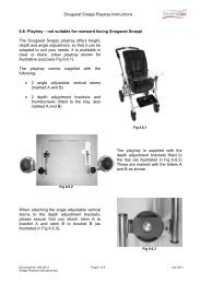
Snazzi Pushchair Workshop ManualOnce the covers are removed, adjust thefootrest knee angle so that the footreststems sit in line with the seat as shown (seeFig 7.6.1). For details on adjusting thefootrest knee angle please refer to the user<strong>manual</strong>.Fig 7.6.1Next, fold the foot plate flat as shown (seeFig 7.6.2).Fig 7.6.2Fold the entire seat section up to reveal theunderside of the seat as shown (see Fig7.6.3). Make sure the 4 thumb screws aretight (to prevent the coach bolt turning), thenusing a 13mm socket or spanner remove the4 nylock dome nuts.Fig 7.6.3Document No: 055-05 v1b Page 21 of 29 August 2012Snazzi Pushchair Workshop Manual.docx
Snazzi Pushchair Workshop ManualNext, remove the 4 thumbscrews and setaside (see Figs 7.6.4 and 7.6.5).Fig 7.6.4Fig 7.6.5, Left: The seat base with the 4thumbscrews removed.Fig 7.6.5Fold the seat base back down to its normalposition; remove the 4 coach bolts (seearrows, Fig 7.6.6) holding the hip guidesonto the base.Fig 7.6.6Document No: 055-05 v1b Page 22 of 29 August 2012Snazzi Pushchair Workshop Manual.docx
Snazzi Pushchair Workshop ManualFinally remove the hip guides. When fittingthe new hip guides be careful to take note ofthe position of the 4 black spacer washers(see arrows, Fig 7.6.7), ensuring that theyline up with the mounting holes in the baseplate. Also make sure the slots in the upperbase plate line up with the front mountingholes.Fig 7.6.7• Next, place the new hip guides on top of the upper base plate and washers so thatthe lateral slots in the hip guides line up with the holes in the washers, lower baseplate and base holes.• Secure the new hip guides in place by placing the coach bolts through the hip guideslots, upper base slots / washers and base mounting holes. With the seat in the flatposition, secure the bolts in place using the 4 thumbscrews.• Tighten the screws, then place 4 M8 nylock nuts onto the end of the threads of thecoach bolts to prevent the thumbscrews being lost. Tighten the nuts to the point thatthe screw threads are into the nylon insert, but so that there is still sufficient freethread on coach bolts that the thumbscrews can be undone to adjust the hip guidesand seat depth.• Finally re-attach any covers or harnessing removed (for details on fitting the coversand harnesses please refer to the user <strong>manual</strong>).Document No: 055-05 v1b Page 23 of 29 August 2012Snazzi Pushchair Workshop Manual.docx
Snazzi Pushchair Workshop Manual7.7: Footrest Parts:If a complete footrest assembly is ordered, it comes supplied with footrest slide with the traypre-assembled, footrest stems and the angle adjustors. For information on fitting theseplease refer to the instructions given in section 7.7.1 (for the angle adjustors), and 7.7.2 (forthe stems) and 7.7.4 (for the slide and tray assembly) below.7.7.1: Knee Angle Adjustors:To replace the knee angle adjustors:First remove the M5 bolt securing thefootrest stems into the adjustors using a3mm hexagon key and 8mm socket orspanner as shown (see Fig 7.7.1.1). Takenote of the position of the washers.Fig 7.7.1.1Take the footrest stems (complete with thefootrest and slide) out from the adjustors andset aside.Fig 7.7.1.2Document No: 055-05 v1b Page 24 of 29 August 2012Snazzi Pushchair Workshop Manual.docx
Snazzi Pushchair Workshop ManualFig 7.7.1.3 Right: The adjustors with thefootrest and stems removed.Fig 7.7.1.3Fold the seat base up to get easy access tothe underside of the seat. Using a 3mmhexagon key and an 8mm socket or spannerremove the M5 bolt securing the back of theangle adjustor as shown (see Fig 7.7.1.4).Take note of the position of the washers.Fig 7.7.1.4Document No: 055-05 v1b Page 25 of 29 August 2012Snazzi Pushchair Workshop Manual.docx
Snazzi Pushchair Workshop ManualFig 7.7.1.5 Right: The seat base poles withthe adjustor removed.When fitting the new adjustors, ensure thatthe release buttons are facing towards theoutsides, and refit with new Nylock domenuts- do not reuse Nylock nuts.Fig 7.7.1.57.7.2: Footrest Stems:To replace the footrest stems:Set the footrest knee angle so that thefootrest stems are in line with the seat, andfold the footplate flat against the stems (formore details on adjusting the footrest andknee angle please refer to the user <strong>manual</strong>).Fold the footrest and seat base up to provideaccess to the back of the footrest stems.Using a screwdriver remove the 2 selftappingscrews from the bottom of thefootrest stems as shown (see Fig 7.7.2.1).Fig 7.7.2.1Document No: 055-05 v1b Page 26 of 29 August 2012Snazzi Pushchair Workshop Manual.docx
Snazzi Pushchair Workshop ManualNext, undo the 2 M8 locking bolts on thefootrest slide using a 5mm hexagon key (seeFig 7.7.2.2).Slide the footrest slide assembly off of thefootrest stems.Fig 7.7.2.2Finally, undo the M5 bolt securing thefootrest stem to the knee angle adjustorusing a 3mm hexagon key and 8mm socketor spanner as shown (see Fig 7.7.2.3). Takenote of the position of the washers.Fig 7.7.2.3To fit the new stems: Follow the reverse of this procedure, and fit with a new Nylock domenut (never re-use Nylock nuts).Document No: 055-05 v1b Page 27 of 29 August 2012Snazzi Pushchair Workshop Manual.docx
Snazzi Pushchair Workshop Manual7.7.3: Footrest Tray:Replace if damaged or worn:Set the knee angle to 45 degrees as shown(see fig 7.7.3.1). For more details of how toadjust the footrest knee angle please refer tothe user <strong>manual</strong>.Fig 7.7.3.1Using a 5mm hexagon key and a 13mmsocket or spanner remove the M8countersunk bolts that secure the footresttray to the footrest slide as shown (see Fig7.7.3.2). Take note of the position of thewashers.Fig 7.7.3.2To fit the new tray, attach it to the footrest slide using the countersunk bolts and washersremoved from the old tray. Secure with new Nylock dome nuts, do not reuse Nylock nuts.7.7.4: Footrest Slide Assembly:The footrest slide assembly will come pre-assembled complete with the plastic tray. To fitthe new assembly, simply remove the old slide assembly following the instructions given insection 7.7.2 above. Slide the new assembly onto the footrest stems and secure back inplace.Document No: 055-05 v1b Page 28 of 29 August 2012Snazzi Pushchair Workshop Manual.docx
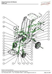
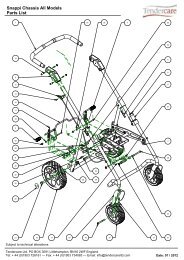
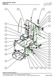
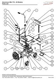
Snazzi Pushchair Workshop Manual8: Cleaning1. To clean the wheelbase or interface, wipe with a damp cloth and dry thoroughly.2. For more stubborn stains wipe with a damp cloth and warm water in which a littlemild soap has been dissolved. Dry thoroughly.3. Never use furniture polish or any spirit to clean the frame.9: Parts ListsPlease refer to the parts list / exploded diagram for ordering information of any partsneeded for the Snazzi. The parts list is available on the website as;• ‘Snazzi Pushchair Parts List’ (applies to both sizes of <strong>pushchair</strong>).Document No: 055-05 v1b Page 29 of 29 August 2012Snazzi Pushchair Workshop Manual.docx