TAU MEC1000-2000 Board Connections (Text)
TAU MEC1000-2000 Board Connections (Text)
TAU MEC1000-2000 Board Connections (Text)

You also want an ePaper? Increase the reach of your titles
YUMPU automatically turns print PDFs into web optimized ePapers that Google loves.
CONNECTIONS TO THE TERMINAL BOARD<br />
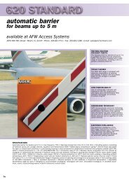
AFW Access Systems<br />
3670 NW 79 th Street<br />
Miami, FL 33147<br />
Phone: 305-691-7711 • Fax: 305-693-1386<br />
Web Site: www.AnchorMiami.com<br />
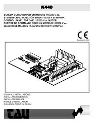
MEC 1000 – <strong>2000</strong><br />
1-2 OPTIONAL: 12 VDC POWER SUPPLY supplementary voltages INPUT<br />
+ Terminal 1, - Terminal 2. Contacts may only be used with the stabilizer card.<br />
3-4 12 VDC 6Ah DRY BATTERY input,<br />
The battery powers the panel for 24 h in the standby mode and approx. 20 minutes if the motor is<br />
working (approx. 30 maneuvers).<br />
+ Terminal 3, - Terminal 4.<br />
5-6 12 V OUTPUT 12 VDC outlet, max. 20 W.<br />
For power supply to RECEIVERS and PHOTOCELLS, etc<br />
Protected by a 3,15A fuse (5x20).<br />
+ Terminal 5, - Terminal 6.<br />
7-8 M1 motor output 12 VDC max. 50 W.<br />
Connect the motor with the electric lock. Delayed action during closing (this delay can be adjusted<br />
with dip-switches 7A and 8A). Protected by a 12 Ah fuse.<br />
9-10 M2 motor outlet 12 VDC max. 50 W.<br />
Connect the motor without the electric lock. Delayed action during opening. (Fixed delay).<br />
Protected by a 12 Ah fuse.<br />
11-14 12 VDC output for FLASHING LIGHT, max. 20 W. + Terminal 11, -Terminal 14 (Common=14).<br />
12-14 INDICATOR LIGHT OUTPUT 12 VDC max. 15 W.<br />
This lights up at the beginning of the opening phase until the gate is totally closed.<br />
+ Terminal 12, -Terminal 14 (Common=14).<br />
13-14 ELECTRIC LOCK OUTPUT 12 VDC max. 15 W.<br />
This is active for 1 second before and 3 seconds after the close delay door (M1) starts opening.<br />
DIP 2B can be used to select the courtesy light which remains on for approx. 3 minutes after the<br />
maneuver has terminated. + Terminal 13, - Terminal 14 (Common=14).<br />
15-17 PEDESTRIAN pushbutton input (Normally Open contact); this does exactly the same job as the<br />
OPEN/CLOSE pushbutton; DIP 1A is used to control this function. (Common=17).<br />
If the card is configured for 2 motors the pedestrian impulse completely opens the M1 motor door.<br />
If it is configured for one motor the pedestrian open function can be programmed as preferred.
16-17 OPEN/CLOSE (or STEP-BY-STEP) push button input. Dipswitches 3A and 1A (CONTROL CARD)<br />
are used to control this input. DS 3A can be used to disable the inversion of direction during the<br />
opening phase, while DS 1A enables the OPEN/STOP/CLOSE/STOP function; Normally Open<br />
contact. (Common=17).<br />
When DIP 1 B is ON (2 motors) the open-close and pedestrian functions are active, if DIP 1 B is<br />
OFF (one motor) the following can happen:<br />
when DIP8 is OFF the open-close and pedestrian functions are normal, when DIP8 is ON the openclose<br />
button becomes just an open button while the pedestrian button becomes the close button.<br />
17-18 STOP BUTTON. This button stops the gate no matter what maneuver it's making. Press the<br />
OPEN/CLOSE button to start the gate moving again.<br />
Normally closed contact. (Common=17).<br />
17-19 PHOTO DEVICE safety input for PHOTOCELLS, SAFETY EDGES, etc… DIP 2A is used to control<br />
this function. Normally closed contact. (Common=17).<br />
17-20 MOBILE SAFETY EDGE - PHOTO DEVICE controlled by DIP 1 B.<br />
Normally closed contact. (Common=17).<br />
If DIP1 is OFF (1 motor), it works as a fixed edge, during the opening phase the control will cause<br />
the gate to close for about 2 seconds.<br />
If DIP1 is OFF (2 motors), it works as a photocell; if it cuts in during the closing phase the gate will<br />
totally reopen, while it will remain inactive during the closing phase.<br />
21-22-23 MOTOR 1 (M1) ENCODER INPUT.<br />
Terminal n° 21,+ / brown,<br />
Terminal n° 22, - / blue,<br />
Terminal n° 23 control pulse / white.<br />
21-22-24 MOTOR 2 (M2) ENCODER INPUT (only for MEC<strong>2000</strong>).<br />
Terminal n° 21,+ / brown,<br />
Terminal n° 22, - / blue,<br />
Terminal n° 24 control pulse / white.<br />
25-26 2 nd RADIO CHANNEL OUTPUT OF 2 nd RADIO CHANNEL<br />
When a two-channel receiver is used, the lighting installation, another piece of equipment, etc.,<br />
can be controlled.<br />
Please see the receiver instructions for details of electrical connections.<br />
27-28 RECEIVING AERIAL INPUT (Please also see further receiver instructions for 433.92 MHz<br />
frequency). Connect the SHEATH to terminal n° 28 and the CABLE to terminal n° 27. If there is no<br />
suitable earth connection the aerial sheath should not be connected.<br />
29-29 13.5 VAC input from toroidal transformer (fig. 2 - 3).<br />
30-31 230 VAC input to toroidal transformer (fig. 2 - 3).<br />
32-33 230 VAC mains power supply input (fig. 2 - 3).<br />
INSTALLATION<br />
1- Position the card vertically.<br />
2- Make sure to respect the polarities.<br />
3- Different wires should be used for different circuits.<br />
4- The cross-section of the cables of the mains line and the motor lines must be calculated to suit their length and<br />
absorption levels.<br />
Recommended cross-section of power cables 1.5 mm²<br />
Recommended cross-section of motor cables 2.5 mm²
5- Install the electrical panel at not more than 5 m from the motor reducers. When the control circuits<br />
comprise very long lines (over 50 m) it should be decoupled with relays installed in the control panel.<br />
6- The ducts entering and leaving the equipment must be preferably installed by keeping the initial level of<br />
protection unaltered (IP43).<br />
7- If a fuse blows, it must be replaced with another one of the same type.<br />
8- Connect the Normally Closed contacts that are not used to the common.<br />
TESTING THE INSTALLATION<br />
The small green LED's indicate N.C. inputs; if the contacts are closed the LED's must be on (if N.C. inputs are not<br />
used, they must be connected to the common circuit).<br />
L1 red<br />
L2 red<br />
L3 green<br />
L4 green<br />
L5 green<br />
Indicates the pedestrian command is working (on while signal is being received).<br />
Indicates the step-by-step command is working (on while signal is being received).<br />
Indicates the stop command is working (off while signal is being received).<br />
Indicates the photocell input is working (off while signal is being received).<br />
Indicates the fixed edge – photo device is working (off while signal is being received).<br />
L6+L7 green/red Indicates the card is powered.<br />
L7 green<br />
L8 red<br />
Indicates terminals 32-33 are powered at 230 VAC.<br />
Indicated the card I battery powered at 12 VDC.<br />
DIPSWITCH SETTING<br />
DIPSWITCH “A”<br />
N° 1A STOP BUTTON OPEN/CLOSE ON stop enabled.<br />
When this dipswitch is OFF the open/close button works as described in under dip-switch 3A.<br />
When the dipswitch is ON and any start button is pressed the following phases will occur:<br />
OPEN - STOP - CLOSE - STOP - OPEN etc<br />
N° 2A PHOTO DEVICE IN THE OPENING PHASE ON also enabled in the opening phase.<br />
When this dipswitch is OFF the photo device only cuts in during the CLOSING phase; it blocks<br />
for about 2 seconds and then carries out an opening maneuver.<br />
When this dipswitch is ON the photo device ALSO cuts in during the OPENING phase, the gate<br />
stops moving until the obstacle interrupts the beam of the photo device and an opening<br />
maneuver will be carried out after reset.<br />
N° 3A OPEN/CLOSE BUTTON IN THE OPENING PHASE ON also enabled in the opening phase.<br />
When the dipswitches are in the OFF position the open/close button only inverts the direction of<br />
movement during the CLOSING phase. In the ON position, the open/close button ALSO inverts<br />
the direction of movement during the OPENING phase.<br />
N° 4A AUTOMATIC RE-CLOSING ON enabled.<br />
In the OFF position, the gate will only close after a manual command after it has opened.
In the ON position, the gate is AUTOMATICALLY CLOSED following a set PAUSE time after<br />
it has opened.<br />
N° 5A-6A SLOWING DOWN 4 levels.<br />
The slowing down phase is the final part of the travel of the gate during which the motor<br />
rotates at a lower speed in order to prevent it from stopping too suddenly. The duration of this<br />
phase depends on the pulses read by the encoder during the memorizing operation.<br />
MIN<br />
↕<br />
MAX<br />
DIP No. 5 DIP No. 6 % EXAMPLE with 100 pulses memorized:<br />
OFF OFF 4.68 95.32 pulses at normal speed, 4.68 pulses at reduced speed<br />
ON OFF 12.5 87.5 pulses at normal seed, 12.5 pulses at reduced seed<br />
OFF ON 37.5 62.5 pulses at normal speed, 37.5 pulses at reduced speed<br />
ON ON 50 50 pulses at normal speed, 50 pulses at reduced speed<br />
N° 7A-8A DOOR DELAY (MEC<strong>2000</strong>) 4 levels.<br />
The duration of the delay is always proportional to the pulses read by the encoder during the<br />
memorizing operation.<br />
MIN<br />
↕<br />
MAX<br />
DIP No. 7 DIP No. 8 % D.OP % D.CL EXAMPLE with 100 pulses memorized:<br />
OFF OFF 2.34 4.69 2.34 delay open pulses, 4.69 delay close pulses<br />
ON OFF 4.69 9.38 4.69 delay open pulses, 9.38 delay close pulses<br />
OFF ON 9.38 18.75 9.38 delay open pulses, 18.75 delay close pulses<br />
ON ON 18.75 37.5 18.75 delay open pulses, 37.5 delay close pulses<br />
N° 9A-10A ELECTRONIC TYPE CLUTCH 4 levels.<br />
The <strong>MEC1000</strong> / MEC<strong>2000</strong> panel is fitted with an encoder that can control the effective speed of<br />
the gate or the two gates independently in the case of swing gates.<br />
The motor thereby becomes sensitive to any drops in speed that can be caused either by an<br />
obstacle or the mechanical travel stop. This sensitivity can be adjusted to 4 levels with dipswitches<br />
9A and 10A. Fitters should opt for an average maximum power level.<br />
MIN<br />
↕<br />
MAX<br />
DIP No. 9 DIP No. 10 POWER LEVEL<br />
OFF OFF 1 MINIMUM<br />
ON OFF 2 AVERAGE MINIMUM<br />
OFF ON 3 AVERAGE MAXIMUM<br />
ON ON 4 MAXIMUM<br />
DIPSWITCH “B”<br />
N° 1B ON enables 2 motors.<br />
OFF enables just one motor.<br />
NB: 1 motor activates the relays of both motors in parallel but only reads from the M1 motor<br />
encoder.<br />
For use with 2-motor up-and-over doors.<br />
When DIP 7A is OFF, the reversal stroke is enabled to prevent the motor from locking.<br />
For use with sliding gates.<br />
N° 2B ON enables the courtesy light. OFF enables the electric lock. Output 13/14.<br />
N° 3B ON enables the pre-flashing function.<br />
OFF disables the pre-flashing function.<br />
N° 4B ON enables all the memorizing functions.<br />
OFF is the position at which it must stay when memorizing operations have terminated (normal<br />
opening and closing operation).
MEMORIZING WORK AND PAUSE TIME<br />
Exit the automatic cycle and open the door a little.<br />
NB: only for barriers, incline the bar to 45° from horizontal.<br />
1. Move dip 4B to the memorizing position, i.e., ON (fig. 11). The light will start flashing.<br />
2. Give an impulse with the remote control unit or the open/close button (fig. 12). The gate should start<br />
closing; if it opens, suspend programming by resetting the electrical panel (use the tip of a screwdriver to<br />
short circuit the two metal reset pins for a second), and then switch off the panel and invert the motor.<br />
3. About 2 seconds after closing (fig. 13), the gate opens automatically.<br />
4. Wait for a certain amount of time T (as preferred) and then give an impulse to close the door. T becomes<br />
the pause time before automatic closing (if programmed with dip 4A). During all these phases the light<br />
keeps flashing.<br />
5. Now that all the open/close phases have been memorized, move dip 4B to OFF (fig. 14).<br />
6. After memorizing has terminated, make the automatic system carry out a complete maneuver (open/close)<br />
without activating any devices.<br />
MEMORIZING THE PEDESTRIAN OPENING FOR A MOTOR<br />
1. Move dip 4B to ON; the light will start flashing.<br />
2. Press the PEDESTRIAN button; the gate connected to motor M1 will start opening,<br />
3. Stop the gate at the required point by pressing the PEDESTRIAN button.<br />
4. Press the PEDESTRIAN button again or wait for the pause time to elapse for the gate to close.<br />
5. Move dip 4B to the OFF position and check the light stops flashing.<br />
6. Memorizing has now terminated.<br />
MEMORY RESET<br />
If any or all of the previously modified settings need to be changed, proceed as follows:<br />
1. Power the control card.<br />
2. Touch the two pins of the JP1 jump with the tip of a screwdriver for at least 1 second.<br />
3. The previously memorized settings have now been deleted.<br />
The position of dip 4B is irrelevant during this operation.<br />
EQUIPMENT DATA<br />
The control panels for the automatic opening of models MEC 1000 and MEC <strong>2000</strong>, comply with the following<br />
characteristics:<br />
• Power voltage: 19 VDC<br />
• Voltage of the power circuits that supply the motors: 19 VDC<br />
• Auxiliary circuit voltage: 12,5 VDC<br />
• Electronic circuit voltage: 12,5 VDC<br />
• The equipment is guaranteed to work outdoors under normal working conditions that are specified below:<br />
Ambient temperatures no higher than 104°F (average value referring to a time of 24 hours no higher<br />
than 95°F)<br />
Ambient temperatures no lower than -13°F<br />
Temporary relative humidity up to 100% at 77°F<br />
Nominal current of the motor's power circuit: 12 A for each motor<br />
Nominal current of the auxiliary circuits: 2 A.