HCI 534D/544D - Technical Data Sheet
HCI 534D/544D - Technical Data Sheet
HCI 534D/544D - Technical Data Sheet

Create successful ePaper yourself
Turn your PDF publications into a flip-book with our unique Google optimized e-Paper software.
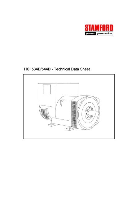
<strong>HCI</strong> <strong>534D</strong>/<strong>544D</strong> - <strong>Technical</strong> <strong>Data</strong> <strong>Sheet</strong>
<strong>HCI</strong><strong>534D</strong>/<strong>544D</strong><br />
SPECIFICATIONS & OPTIONS<br />
STANDARDS<br />
Newage Stamford industrial generators meet the<br />
requirements of BS EN 60034 and the relevant section<br />
of other international standards such as BS5000, VDE<br />
0530, NEMA MG1-32, IEC34, CSA C22.2-100, AS1359.<br />
Other standards and certifications can be considered on<br />
request.<br />
VOLTAGE REGULATORS<br />
SX440 AVR - STANDARD<br />
With this self-excited system the main stator provides<br />
power via the Automatic Voltage Regulator (AVR) to the<br />
exciter stator. The high efficiency semi-conductors of<br />
the AVR ensure positive build-up from initial low levels<br />
of residual voltage.<br />
The exciter rotor output is fed to the main rotor through<br />
a three-phase full-wave bridge rectifier. The rectifier is<br />
protected by a surge suppressor against surges<br />
caused, for example, by short circuit or out-of-phase<br />
paralleling.<br />
The SX440 will support a range of electronic<br />
accessories, including a 'droop' Current Transformer<br />
(CT) to permit parallel operation with other ac<br />
generators.<br />
If 3-phase sensing is required with the self-excited<br />
system, the SX421 AVR must be used.<br />
SX421 AVR<br />
This AVR also operates in a self-excited system. It<br />
combines all the features of the SX440 with,<br />
additionally, three-phase rms sensing for improved<br />
regulation and performance. Over voltage protection is<br />
provided via a separate circuit breaker. An engine relief<br />
load acceptance feature is built in as standard.<br />
MX341 AVR<br />
This sophisticated AVR is incorporated into the<br />
Stamford Permanent Magnet Generator (PMG) control<br />
system.<br />
The PMG provides power via the AVR to the main<br />
exciter, giving a source of constant excitation power<br />
independent of generator output. The main exciter<br />
output is then fed to the main rotor, through a full wave<br />
bridge, protected by a surge suppressor. The AVR has<br />
in-built protection against sustained over-excitation,<br />
caused by internal or external faults. This de-excites<br />
the machine after a minimum of 5 seconds.<br />
An engine relief load acceptance feature can enable full<br />
load to be applied to the generator in a single step.<br />
If three-phase sensing is required with the PMG system<br />
the MX321 AVR must be used.<br />
We recommend three-phase sensing for applications<br />
with greatly unbalanced or highly non-linear loads.<br />
MX321 AVR<br />
The most sophisticated of all our AVRs combines all the<br />
features of the MX341 with, additionally, three-phase<br />
rms sensing, for improved regulation and performance.<br />
Over voltage protection is built-in and short circuit<br />
current level adjustments is an optional facility.<br />
WINDINGS & ELECTRICAL PERFORMANCE<br />
All generator stators are wound to 2/3 pitch. This<br />
eliminates triplen (3rd, 9th, 15th …) harmonics on the<br />
voltage waveform and is found to be the optimum<br />
design for trouble-free supply of non-linear loads. The<br />
2/3 pitch design avoids excessive neutral currents<br />
sometimes seen with higher winding pitches, when in<br />
parallel with the mains. A fully connected damper<br />
winding reduces oscillations during paralleling. This<br />
winding, with the 2/3 pitch and carefully selected pole<br />
and tooth designs, ensures very low waveform<br />
distortion.<br />
TERMINALS & TERMINAL BOX<br />
Standard generators are 3-phase reconnectable with 12<br />
ends brought out to the terminals, which are mounted<br />
on a cover at the non-drive end of the generator. A<br />
sheet steel terminal box contains the AVR and provides<br />
ample space for the customers' wiring and gland<br />
arrangements. It has removable panels for easy<br />
access.<br />
SHAFT & KEYS<br />
All generator rotors are dynamically balanced to better<br />
than BS6861:Part 1 Grade 2.5 for minimum vibration in<br />
operation. Two bearing generators are balanced with a<br />
half key.<br />
INSULATION/IMPREGNATION<br />
The insulation system is class 'H'.<br />
All wound components are impregnated with materials<br />
and processes designed specifically to provide the high<br />
build required for static windings and the high<br />
mechanical strength required for rotating components.<br />
QUALITY ASSURANCE<br />
Generators are manufactured using production<br />
procedures having a quality assurance level to BS EN<br />
ISO 9001.<br />
The stated voltage regulation may not be maintained in<br />
the presence of certain radio transmitted signals. Any<br />
change in performance will fall within the limits of<br />
Criteria 'B' of EN 61000-6-2:2001. At no time will the<br />
steady-state voltage regulation exceed 2%.<br />
NB Continuous development of our products entitles us<br />
to change specification details without notice, therefore<br />
they must not be regarded as binding.<br />
Front cover drawing typical of product range.<br />
2
<strong>HCI</strong><strong>534D</strong>/<strong>544D</strong><br />
WINDING 311<br />
CONTROL SYSTEM<br />
SEPARATELY EXCITED BY P.M.G.<br />
A.V.R. MX321 MX341<br />
VOLTAGE REGULATION ± 0.5 % ± 1.0 % With 4% ENGINE GOVERNING<br />
SUSTAINED SHORT CIRCUIT REFER TO SHORT CIRCUIT DECREMENT CURVES (page 7)<br />
CONTROL SYSTEM<br />
SELF EXCITED<br />
A.V.R. SX440 SX421<br />
VOLTAGE REGULATION ± 1.0 % ± 0.5 % With 4% ENGINE GOVERNING<br />
SUSTAINED SHORT CIRCUIT SERIES 4 CONTROL DOES NOT SUSTAIN A SHORT CIRCUIT CURRENT<br />
INSULATION SYSTEM<br />
CLASS H<br />
PROTECTION<br />
RATED POWER FACTOR<br />
STATOR WINDING<br />
WINDING PITCH<br />
WINDING LEADS<br />
STATOR WDG. RESISTANCE<br />
ROTOR WDG. RESISTANCE<br />
R.F.I. SUPPRESSION<br />
WAVEFORM DISTORTION<br />
MAXIMUM OVERSPEED<br />
BEARING DRIVE END<br />
BEARING NON-DRIVE END<br />
WEIGHT COMP. GENERATOR<br />
WEIGHT WOUND STATOR<br />
WEIGHT WOUND ROTOR<br />
WR² INERTIA<br />
0.005 Ohms PER<br />
61000-6-2 & BS EN<br />
LOAD < 1.5%<br />
1 BEARING<br />
1393 kg<br />
657 kg<br />
563 kg<br />
8.0068 kgm 2 IP23<br />
0.8<br />
DOUBLE LAYER LAP<br />
TWO THIRDS<br />
12<br />
PHASE AT 22°C SERIES<br />
1.77 Ohms at 22°C<br />
61000-6-4,VDE 0875G, VDE<br />
NON-DISTORTING BALANCED<br />
2250 Rev/Min<br />
BALL. 6220 (ISO)<br />
BALL. 6314 (ISO)<br />
CONNECTED<br />
refer to factory<br />
LINEAR LOAD < 5.0%<br />
2 BEARING<br />
1395 kg<br />
657 kg<br />
535 kg<br />
7.7289 kgm 2<br />
STAR<br />
BS EN 0875N. for others<br />
NO<br />
SHIPPING WEIGHTS in a crate<br />
PACKING CRATE SIZE<br />
1485 kg<br />
166 x 87 x 124(cm)<br />
1485 kg<br />
166 x 87 x 124(cm)<br />
50 Hz<br />
TELEPHONE INTERFERENCE<br />
COOLING AIR<br />
THF
50<br />
Hz<br />
<strong>HCI</strong><strong>534D</strong>/<strong>544D</strong><br />
Winding 311<br />
THREE PHASE EFFICIENCY CURVES<br />
4
<strong>HCI</strong><strong>534D</strong>/<strong>544D</strong><br />
Winding 311<br />
THREE PHASE EFFICIENCY CURVES<br />
60<br />
Hz<br />
5
<strong>HCI</strong><strong>534D</strong>/<strong>544D</strong><br />
Winding 311<br />
Locked Rotor Motor Starting Curve<br />
MX<br />
50<br />
Hz<br />
SX<br />
30<br />
346V 380V 400V 415V 440V<br />
30<br />
346V 380V 400V 415V 440V<br />
25<br />
25<br />
PER CENT TRANSIENT VOLTAGE DIP .<br />
20<br />
15<br />
10<br />
PER CENT TRANSIENT VOLTAGE DIP .<br />
20<br />
15<br />
10<br />
5<br />
5<br />
0<br />
0 200 400 600 800 1000 1200 1400 1600 1800<br />
LOCKED ROTOR kVA<br />
0<br />
0 200 400 600 800 1000 1200 1400<br />
LOCKED ROTOR kVA<br />
MX<br />
60<br />
Hz<br />
SX<br />
30<br />
380V 416V 440V 460V 480V<br />
30<br />
380V 416V 440V 460V 480V<br />
25<br />
25<br />
PER CENT TRANSIENT VOLTAGE DIP .<br />
20<br />
15<br />
10<br />
PER CENT TRANSIENT VOLTAGE DIP .<br />
20<br />
15<br />
10<br />
5<br />
5<br />
0<br />
0 200 400 600 800 1000 1200 1400 1600 1800 2000<br />
LOCKED ROTOR kVA<br />
0<br />
0 200 400 600 800 1000 1200 1400 1600<br />
LOCKED ROTOR kVA<br />
6
50<br />
Hz<br />
<strong>HCI</strong><strong>534D</strong>/<strong>544D</strong><br />
Three-phase Short Circuit Decrement Curve. No-load Excitation at Rated Speed<br />
Based on star (wye) connection.<br />
100000<br />
SYMMETRICAL<br />
ASYMMETRICAL<br />
CURRENT (Amps)<br />
10000<br />
1000<br />
100<br />
0.001 0.01 0.1 1 10<br />
TIME (secs)<br />
Sustained Short Circuit = 2,400 Amps<br />
60<br />
Hz<br />
100000<br />
SYMMETRICAL<br />
CURRENT (Amps)<br />
10000<br />
1000<br />
ASYMMETRICAL<br />
100<br />
0.001 0.01 0.1 1 10<br />
TIME (secs)<br />
Sustained Short Circuit = 2,500 Amps<br />
Note 1<br />
Note 2<br />
The following multiplication factors should be The following multiplication factor should be used to convert the<br />
used to adjust the values from curve between values calculated in accordance with NOTE 1 to those applicable<br />
time 0.001 seconds and the minimum current to the various types of short circuit :<br />
point in respect of nominal operating voltage :<br />
50Hz<br />
60Hz<br />
3-phase 2-phase L-L 1-phase L-N<br />
Voltage Factor Voltage Factor Instantaneous<br />
x 1.00 x 0.87 x 1.30<br />
380v X 1.00 416v X 1.00 Minimum<br />
x 1.00 x 1.80 x 3.20<br />
400v X 1.06 440v X 1.06 Sustained<br />
x 1.00 x 1.50 x 2.50<br />
415v X 1.09 460v X 1.12 Max. sustained duration<br />
10 sec. 5 sec. 2 sec.<br />
440v X 1.12 480v X 1.20<br />
All other times are unchanged<br />
The sustained current value is constant irrespective Note 3<br />
of voltage level<br />
Curves are drawn for Star (Wye) connected machines. For other<br />
connection the following multipliers should be applied to current<br />
values as shown :<br />
Parallel Star = Curve current value X 2<br />
Series Delta = Curve current value X 1.732<br />
7
<strong>HCI</strong><strong>534D</strong>/<strong>544D</strong><br />
Winding 311 0.8 Power Factor<br />
RATINGS<br />
Class - Temp Rise<br />
Cont. F - 105/40°C Cont. H - 125/40°C Standby - 150/40°C Standby - 163/27°C<br />
50<br />
Hz<br />
Series Star (V) 380 400 415 440 380 400 415 440 380 400 415 440 380 400 415 440<br />
Parallel Star (V) 190 200 208 220 190 200 208 220 190 200 208 220 190 200 208 220<br />
Series Delta (V) 220 230 240 254 220 230 240 254 220 230 240 254 220 230 240 254<br />
kVA 450 495 450 450 500 550 500 500 515 575 515 515 530 590 530 530<br />
kW 360 396 360 360 400 440 400 400 412 460 412 412 424 472 424 424<br />
Efficiency (%) 94.8 94.7 95.0 95.1 94.5 94.3 94.8 94.9 94.4 94.1 94.7 94.9 94.2 94.0 94.6 94.8<br />
kW Input 380 418 379 379 423 467 422 421 436 489 435 434 450 502 448 447<br />
60<br />
Hz<br />
Series Star (V) 416 440 460 480 416 440 460 480 416 440 460 480 416 440 460 480<br />
Parallel Star (V) 208 220 230 240 208 220 230 240 208 220 230 240 208 220 230 240<br />
Delta (V) 240 254 266 277 240 254 266 277 240 254 266 277 240 254 266 277<br />
kVA 519 538 563 588 575 594 625 644 588 625 655 675 606 644 673 694<br />
kW 415 430 450 470 460 475 500 515 470 500 524 540 485 515 538 555<br />
Efficiency (%) 94.7 94.8 94.9 94.9 94.5 94.6 94.6 94.7 94.4 94.4 94.5 94.5 94.3 94.3 94.4 94.4<br />
kW Input 438 454 475 496 487 502 529 544 498 530 554 571 514 546 570 588<br />
DIMENSIONS<br />
© 2002 Newage International Limited.<br />
Reprinted with permission of N.I. only.<br />
Printed in England.<br />
PO Box 17 • Barnack Road • Stamford • Lincolnshire • PE9 2NB<br />
Tel: 00 44 (0)1780 484000 • Fax: 00 44 (0)1780 484100<br />
Website: www.newage-avkseg.com<br />
TD_<strong>HCI</strong>5D.GB_08.02_01_GB