

The SEM35 Manpack - VMARSmanuals
The SEM35 Manpack - VMARSmanuals
The SEM35 Manpack - VMARSmanuals

You also want an ePaper? Increase the reach of your titles
YUMPU automatically turns print PDFs into web optimized ePapers that Google loves.
<strong>The</strong> VMARS Newsletter Issue 12<br />
output stage. Unusually, the volume control is<br />
between the AF output transformer and the<br />
handset. <strong>The</strong> handset is an H-33*/PT as used on<br />
the PRC-10 series, complete with a U-77/U<br />
connector.<br />
<strong>The</strong> squelch circuit has a relay output.<br />
<strong>The</strong> receiver first local oscillator is frequency<br />
stabilised by the synthesiser. A signal from the<br />
receiver local oscillator goes via a buffer amplifier<br />
to the first mixer of the synthesiser. <strong>The</strong> local<br />
oscillator signal for this mixer is generated from a<br />
1 MHz crystal oscillator. <strong>The</strong> 1 MHz oscillator<br />
output is clipped and shaped to make it rich in<br />
harmonics and then passed through an LPF to the<br />
mixer. <strong>The</strong> LPF lets through the 1 MHz<br />
harmonics from 1 to 11 MHz but attenuates the<br />
higher harmonics to ensure that they do not<br />
appear in the receiver tuning range.<br />
<strong>The</strong> synthesiser first IF is a bandpass amplifier<br />
from 46.50 to 47.45 MHz. Only one of the 1 MHz<br />
harmonics can beat with the receiver local<br />
oscillator to produce a signal in the first<br />
synthesiser IF. As with the receiver local<br />
oscillator, the 1 to 11 MHz (0 to 11 MHz) beats<br />
with the receiver local oscillator on a sum and<br />
difference basis to cover the full 22.95 (23) MHz<br />
single band tuning.<br />
<strong>The</strong> local oscillator for the second synthesiser<br />
mixer is an overtone crystal oscillator with one of<br />
two frequencies spaced by 0.500MHz, i.e. 33.425<br />
or 33.925 MHz. <strong>The</strong> overtone oscillator frequency<br />
is remotely selected from switches on the 50 kHz<br />
tuning selector via decoupled control lines that<br />
enable the appropriate oscillator output. <strong>The</strong> two<br />
frequencies are used for alternate bands of<br />
0.500MHz, e.g. one for receiver tuning from 26.00<br />
to 26.45 MHz, the other from 26.5 to 26.95 MHz,<br />
then back to the first from 27.00 to 27.45 and so<br />
on. Both overtone frequencies are midway<br />
between receiver channels and are attenuated by<br />
the receiver IF crystal filter should they leak into<br />
the receiver RF input circuits.<br />
<strong>The</strong> second synthesiser IF is a bandpass amplifier<br />
from 13.075 to 13.525 MHz. <strong>The</strong> local oscillator<br />
for the third synthesiser mixer is controlled by one<br />
of 10 crystals spaced by 50kHz from 14.525 to<br />
14.575 MHz. <strong>The</strong>se are ganged to, and selected<br />
by, the 50 kHz channel selector switch. In<br />
combination with the switched overtone oscillator<br />
for the second synthesiser mixer they provide the<br />
20 off 50 kHz channels per MHz, i.e. the first 10<br />
channels on one overtone oscillator then a further<br />
10 on the second overtone oscillator.<br />
<strong>The</strong> IF output of the third mixer is 1.45 MHz. This<br />
feeds two discriminators, a wideband discriminator<br />
to capture the signal initially and a narrow band<br />
crystal discriminator for the final frequency lock.<br />
<strong>The</strong> discriminator outputs feed a varactor diode in<br />
the receiver local oscillator to complete the<br />
synthesiser loop.<br />
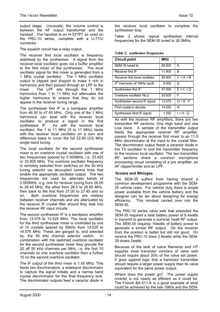
Table 2 shows typical synthesiser internal<br />
frequencies for the SEM-35 tuned to 26.5MHz.<br />
Table 2: synthesiser frequencies<br />
Circuit point<br />
MHz<br />
SEM-35 tuned to 26.500 A<br />
Receiver first IF 11.500 B<br />
Receiver first local oscillator. 38.000 C = A + B<br />
9 th Harmonic of 1MHz oscill. 9.000 D<br />
Synthesiser first IF 47.000 E = C + D<br />
Overtone oscillator No.2 33.925 F<br />
Synthesiser second IF signal 13.075 G = E - F<br />
First crystal in decade 14.525 H<br />
Synthesiser third IF signal 1.450 I = H - G<br />
As with the receiver RF amplifiers, there are two<br />
transmitter RF sections. One High band and one<br />
Low band. A sample of the transmitter output<br />
feeds the appropriate receiver RF amplifier,<br />
passes through the receiver first mixer to an 11.5<br />
MHz discriminator at the input to the crystal filter.<br />
<strong>The</strong> discriminator output feeds a varactor diode in<br />
the TX oscillator to lock the transmitter frequency<br />
to the receiver local oscillator. <strong>The</strong> two transmitter<br />
RF sections share a common microphone<br />
processing circuit consisting of a pre amplifier, an<br />
AF clipper/limiter and an LPF.<br />
Groans and Whinges<br />
<strong>The</strong> SEM-35 suffers from having shared a<br />
common development programme with the SEM-<br />
25 vehicle radio. For vehicle duty there is ample<br />
power available from the vehicle battery and the<br />
designer can be lax about designing for energy<br />
efficiency. This mindset carried over into the<br />
SEM-35.<br />
<strong>The</strong> PRC-10 series valve sets that preceded the<br />
SEM-35 required a total battery power of 8.4watts<br />
in transmit to generate a nominal 1watt RF output.<br />
<strong>The</strong> SEM-35 requires 10watts of battery power to<br />
generate a similar RF output. On the receiver<br />
front the position is better but still not good. On<br />
receive the PRC-10 drew 2.6watts while the SEM-<br />
35 draws 2watts.<br />
Because of the lack of valve filaments and HT<br />
supplies most transistor versions of valve sets<br />
should require about 20% of the valve set power.<br />
It goes against logic that a transistor transmitter<br />
should require a larger power supply than its valve<br />
equivalent for the same power output.<br />
Where does the power go <strong>The</strong> power supply<br />
inverter is not nearly as efficient as it could be.<br />
<strong>The</strong> French BA-511-A is a good example of what<br />
could be achieved by the late 1960s and the SEM-<br />
August 2000 14


