Installation Instructions
Installation Instructions
Installation Instructions

You also want an ePaper? Increase the reach of your titles
YUMPU automatically turns print PDFs into web optimized ePapers that Google loves.
351 Thor Place Brea, Ca 92821 (877) 387-6721<br />
INSTALLATION INSTRUCTIONS<br />
HOOD MODELS – PSX & PEX<br />
PLEASE READ ENTIRE INSTRUCTIONS BEFORE PROCEEDING.<br />
INSTALLATION MUST COMPLY WITH ALL LOCAL CODES.<br />
IMPORTANT: Save these <strong>Instructions</strong> for the Local Electrical Inspector's use.<br />
INSTALLER: Please leave these <strong>Installation</strong>s Instruction with this unit for owner.<br />
OWNER: Please retain these <strong>Instructions</strong> for future reference<br />
IMPORTANT SAFETY INSTRUCTIONS<br />
WARNING - TO REDUCE THE RISK OF FIRE, ELECTRICAL SHOCK, OR INJURY TO PERSONS, HOODS<br />
SHOULD BE INSTALLED WITH VENTILATORS APPROVED FOR USE WITH THE HOOD. SEE TABLE –<br />
1 ON THIS PAGE FOR APPROVED VENTILATORS.<br />
WARNING - TO REDUCE THE<br />
RISK OF FIRE, ELECTRIC<br />
SHOCK, OR INJURY TO<br />
PERSONS, OBSERVE THE<br />
FOLLOWING:<br />
A. <strong>Installation</strong> work and Electrical Wiring<br />
Must be Be Done By Qualified<br />
Person(s) In Accordance With All<br />
Applicable Codes & Standards,<br />
Including Fire-Rated Construction.<br />
“WARNING” To Reduce The Risk Of<br />
Fire, Use Only Metal Duct Work.<br />
B. Sufficient air is needed for proper<br />
combustion and exhausting of gases<br />
through the flue (chimney) of fuel<br />
burning equipment to prevent<br />
backdrafting. Follow the heating<br />
equipment manufactures guideline and<br />
Safety standards such as those<br />
published by the National Fire<br />
Protection Association (NFPA) and the<br />
American Society for Heating,<br />
Refrigeration and Air Conditioning<br />
Engineers (ASHRAE), and the local<br />
code authorities.<br />
C. When cutting or drilling into wall or<br />
ceiling, do not damage electrical wiring<br />
and other hidden utilities.<br />
D. Ducted fans must always be vented to<br />
the outdoors.<br />
E. D. Before Servicing or Cleaning Unit,<br />
Switch Power off At Service Panel And<br />
Lock Service Disconnecting Means to<br />
Prevent Power From Being Switched<br />
On Accidentally. When The Service<br />
Disconnecting Means Cannot be<br />
Locked, Securely Fasten A Prominent<br />
Warning Device, Such As A Tag, To<br />
The Service Panel.<br />
CAUTION - TO REDUCE THE RISK OF FIRE AND TO PROPERLY EXHAUST AIR, BE SURE TO DUCT<br />
AIR OUTSIDE FOR DUCTED FANS – DO NOT VENT EXHAUST AIR INTO SPACE WITHIN WALLS OR<br />
CEILING OR INTO ATTICS, CRAWL SPACES OR GARAGES.<br />
Read this instruction completely before starting installation. Planning the complete installation before starting any<br />
work is highly recommended. This includes all aspects of the installation including hood location, ducting, electrical<br />
requirements, and adequacy of mounting surfaces.<br />
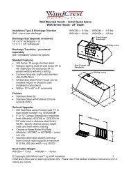
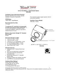
TABLE - 1<br />
Use model VEN060I or<br />
VEN120I for internal ventilator.<br />
Use VEN100E or VEN150E for<br />
remote ventilator<br />
This hood series has been designed to be used with the ventilators shown in Table – 1<br />
(Exception: The VEN120I cannot be used on 30-inch wide Hoods). Before cutting into<br />
cabinets, it is necessary to confirm that the correct ventilator is being used. Your dealer should<br />
have reviewed your needs prior to your purchase. Be sure you have the correct ventilation<br />
system.<br />
CAUTION: To Reduce The Risk Of Fire And Electrical Shock, Install This<br />
Rangehood Only With Blowers Manufactured By Wind Crest.<br />
DUCTING: Use a minimum 8" round duct for VEN060I installations. Use a minimum 10" round duct for VEN120I, VEN100E and<br />
VEN150E installations. See Page – 3 for Transition (Purchased Separately) Recommendations.<br />
SAFTY WARNING:<br />
Turn off power circuit at<br />
the service entrance and<br />
lockout panel before<br />
wiring the range hood.<br />
BACKDRAFT DAMPER: It is recommended that a backdraft damper be used in all installations.<br />
In cold weather installations it is necessary to use a backdraft damper to minimize backflow of cold air<br />
into room. A non-metallic thermal break should also be installed to minimize conduction of outside<br />
temperatures through the ductwork. The thermal break should be located as close as possible to where<br />
the ducting enters the heated portion of the house.<br />
NOTE: Unit must be vented<br />
to outside of the building.<br />
Page1 of 4 P/N 11276.00 Rev D
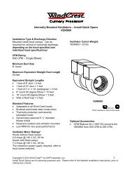
BEFORE STARTING INSTALLATION, YOU MUST IDENTIFY THE VENTILATOR MODEL BEING USED.<br />
For knock out removal see Fig- A<br />
Remove<br />
See<br />
Ventilator Model Knock out # Transition # Fig<br />
VEN060I Top Exhaust 1 10100.00 1,3<br />
VEN120I Top Exhaust 1 & 2 11257.00 1,4<br />
VEN100 & VEN150 1 & 2 11257.00 1,2<br />
External, Top Exhaust<br />
Prepare soffit or other surface for mounting the hood by<br />
using a minimum 3/4 inch thick plywood mounting plate<br />
prepare with the FIG-1. NOTE THAT A MINIMUM<br />
2-3/4 inch soffit overhang is required to achieve a<br />
sufficient structural support base. The overhang, of<br />
course, can be greater than 2-3/4. Note the position of<br />
the hood front relative to the opening in the mounting<br />
plate refer to FIG-5.<br />
Provide an adequate support structure for attaching the<br />
prepared mounting plate to ceiling structure. Local<br />
building codes should be adhered to at all times.<br />
Remember that your new hood is of sufficient weight<br />
that an adequate support structure is necessary.<br />
Attach and secure the transition to the hood with #6 x<br />
3/8 inch sheet metal screw after inserting one flange of<br />
the transition under the hood flange (Detail instruction is<br />
included with transition). Tape all joints prior to<br />
installing the hood, being careful not expose tape beyond<br />
outer edge of hood top flange. Attach the hood to the<br />
prepared mounting plate and soffit using # 10 wood<br />
screws. Holes are located in the top panel – HINT:<br />
marking and pilot drilling these holes in the mounting<br />
plate will aid installation. The # 10 wood screws should<br />
be a minimum of 3/4 inches long if no other surface is<br />
located between the mounting base and hood. If drywall<br />
or other surfaces are positioned between the hood and<br />
mounting base the #10 wood screws must be longer to<br />
provide a full 3/4” engagement of the screw into the<br />
mounting plate.<br />
HINT: If you find vibration noise is present because of<br />
cabinet/mounting structure use additional screws, in<br />
holes available to rigidize mounting.<br />
Connect 120 volts – 15 amp, 60 Hz power supply<br />
through the conduit hole in the top of hood, connecting<br />
to pigtail in hood junction box white to white, black to<br />
black and connect green ground wire to power supply<br />
ground wire per local codes. The VEN100E and<br />
VEN150E ventilator will require revision of some<br />
wiring in the hood receptacle box, See VEN100E/150E<br />
instruction. See Fig-2<br />
NOTE: VEN150E requires a 20 AMP Power Supply.<br />
All other ventilators require a dedicated 15<br />
AMP Power Supply<br />
If the remote ventilator is used see related instructions.<br />
A 10” duct is required for remote ventilators. See FIG-4<br />
The recommended height from counter top or cooking<br />
surface to the bottom edge of the hood is 30 to 36<br />
inches.<br />
NOTE: Recommended height over BBQ Grills = 36<br />
inches.<br />
Hood is recommended for use over domestic gas or<br />
electric appliances. Not recommended for use over<br />
solid fuel fire appliances<br />
After installing the hood, install the internal blower (see<br />
FIG-3 VEN060I or FIG-4 VEN012I) unit by positioning<br />
the blower into bracket- A, notched blower bracket will<br />
center blower, rotating into position against hood top,<br />
and securing with #8 sheet metal screws via bracket – B.<br />
To ease assembly you should predrive the #8 sheet metal<br />
screws before installing the blower. If the remote<br />
ventilator is used see related instructions.<br />
CAUTION: The hood is of sufficient weight that two<br />
Installers are recommended to prevent injury or damage<br />
to the hood in handling.<br />
Turn the power on at the service entrance and check the<br />
operation of the controls.<br />
NOTE: Be sure that all dampers (Not Supplied) are<br />
operating properly and are free to open.<br />
Fig - A<br />
1 1<br />
2<br />
Electrical Box<br />
Page2 of 4 P/N 11276.00 Rev D
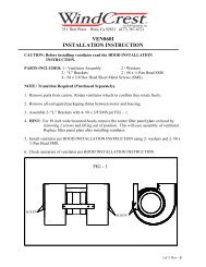
NOTE: Transitions Are Not Included With VEN060I,<br />
VEN100E and VEN150E - Must Be Purchased<br />
Separately.<br />
Transition dimensions may very. Before assembling transitions to<br />
hood, fit them into the prepared cabinet opening to be sure the<br />
openings are large enough to accommodate the transition. Enlarge<br />
the hole if required<br />
14"<br />
9-1/4"<br />
4-1/4"<br />
9-1/4"<br />
13-1/2"<br />
7-3/8"<br />
Attach the transition (See DUCTING, pg 1), obtained separately<br />
from your local hardware or available through your dealer, and<br />
install the hood as described previously in this instruction.<br />
10100.00 11257.00<br />
Fig - 1<br />
Transition <strong>Installation</strong><br />
#10100.00 (8") Or 11257.00 (10")<br />
Models - PSX36, PSX54, PEX42 & PEX54<br />
2"<br />
2"<br />
A<br />
Remove "A" Flange Section<br />
Install Transition To Hood By<br />
Inserting The 2" Tabs On Rear<br />
Of Transition Between Canopy<br />
Flange And The Hood Top Panel<br />
Insert 2" Tabs<br />
Here<br />
Secure Transition To Hood With One<br />
# 6 Sheet Metal Screw And Tape All<br />
Joints, Transition To Hood See Fig - 2<br />
Hood<br />
Apply Screw<br />
From This Side<br />
Transition<br />
Front<br />
A<br />
Model - PEX36<br />
Remove "A" Flange Sections<br />
A<br />
MODEL PSX42<br />
Remove "A" Flange Sections<br />
2"<br />
2"<br />
A<br />
A<br />
Install Transition To Hood By<br />
Inserting The 2" Tabs On Rear<br />
Of Transition Between Canopy<br />
Flange and The Hood Top Panel.<br />
Insert 2" Tabs<br />
Here<br />
Secure Transition To Hood With One<br />
# 6 Sheet Metal Screws and Tape All<br />
Joints, Transition To Hood. See Fig - 2<br />
1 "<br />
3"<br />
3"<br />
1"<br />
A<br />
A<br />
Install Transition To Hood By<br />
Inserting The 1" Tabs On Rear<br />
Of Transition Between Canopy<br />
Flange and The Hood Top Panel.<br />
Insert 1" Tabs<br />
Here<br />
Secure Transition To Hood With One<br />
# 6 Sheet Metal Screws and Tape All<br />
Joints, Transition To Hood. See Fig - 2<br />
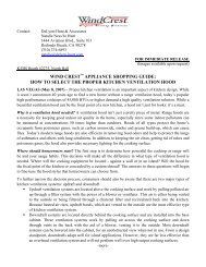
Receptacle Box Cover<br />
Cover Packed With Filters<br />
Hood Top<br />
Knock Outs<br />
Hood Wiring<br />
Cover<br />
Access<br />
Mounting<br />
Screw<br />
Fig - 2<br />
Receptacle Box<br />
Located in Top Of Box<br />
Power Source &<br />
Ground To Hood<br />
Remove Appropriate Knock Outs And Connect Wiring<br />
According To Hood And Blower <strong>Installation</strong> <strong>Instructions</strong>.<br />
CAUTION: Always Install Receptacle Box Cover.<br />
Pull Wires Through When<br />
Positioning Hood In Place<br />
Remove Bottom Cover<br />
For Wiring Access<br />
Page3 of 4 P/N 11276.00 Rev D
Fig - 3<br />
REMOVE KNOCK OUT #1<br />
AIR FLOW<br />
Use #10100.00<br />
Transition<br />
To 8" Duct<br />
Fig - 4<br />
Remove Knock Out # 1 & 2<br />
Air Flow<br />
Use #11257.00<br />
Transition<br />
To 10" Duct<br />
B<br />
A<br />
B<br />
A<br />
Rotate<br />
into<br />
Position<br />
Secure<br />
With 2 Screws<br />
VEN060I<br />
Rotate<br />
into<br />
Position<br />
Secure<br />
With 2 Screws<br />
VEN120I<br />
Hood Model<br />
PEX36<br />
PEX42<br />
PEX54<br />
Dim "A"<br />
20-1/2"<br />
26-1/2"<br />
38-1/2"<br />
Fig - 5<br />
Layout Opening Based On Center Line Of Hood<br />
3/4" Plywood Mounting Plate<br />
14-1/4"<br />
7-1/8"<br />
Hood Model Dim "A"<br />
PSX36 23-1/2"<br />
PSX42 29-1/2"<br />
PSX54 41-1/2"<br />
PSX66 53-1/2"<br />
5-1/8"<br />
5-1/8"<br />
Wiring Access<br />
Area<br />
17-1/2"<br />
Front Of Hood<br />
10-1/2"<br />
"A"<br />
5-1/4"<br />
Power Supply<br />
N G L1<br />
Left<br />
Light<br />
18 BK #12<br />
18 G #11<br />
18 W #13<br />
18 W # 10<br />
18 BK # 7<br />
18 W # 9<br />
18 W # 27<br />
Hood<br />
Receptacle<br />
Box<br />
18 W #25<br />
18 BK #24<br />
18 BLU #23<br />
18 R #22<br />
18 R # 4<br />
12 BK # 1<br />
1<br />
2<br />
3<br />
4<br />
1<br />
2<br />
3<br />
4<br />
Receptacle<br />
Plug<br />
18 BK # 2<br />
18 BLU # 3<br />
3-SPD<br />
Rotary<br />
Switch<br />
18 W<br />
18 BK<br />
18 BLU<br />
18 R<br />
N<br />
HI<br />
MED<br />
LOW<br />
Blower<br />
Motor<br />
Right<br />
Light<br />
Ligth<br />
Switch<br />
1 2<br />
4 5<br />
3<br />
6<br />
18 BK # 6<br />
18 W # 5<br />
1 6<br />
LO<br />
HI<br />
2<br />
MED<br />
4<br />
Wiring Diagram-Internal, Blower & Lighting<br />
18 BK # 8<br />
Page4 of 4 P/N 11276.00 Rev D